EP1536445A2 - Schalter mit einem temperaturabhängigen Schaltwerk - Google Patents
Schalter mit einem temperaturabhängigen Schaltwerk Download PDFInfo
- Publication number
- EP1536445A2 EP1536445A2 EP05004787A EP05004787A EP1536445A2 EP 1536445 A2 EP1536445 A2 EP 1536445A2 EP 05004787 A EP05004787 A EP 05004787A EP 05004787 A EP05004787 A EP 05004787A EP 1536445 A2 EP1536445 A2 EP 1536445A2
- Authority
- EP
- European Patent Office
- Prior art keywords
- cover part
- connection
- connection electrode
- switch according
- contact
- Prior art date
- Legal status (The legal status is an assumption and is not a legal conclusion. Google has not performed a legal analysis and makes no representation as to the accuracy of the status listed.)
- Withdrawn
Links
Images


Classifications
-
- H—ELECTRICITY
- H01—ELECTRIC ELEMENTS
- H01H—ELECTRIC SWITCHES; RELAYS; SELECTORS; EMERGENCY PROTECTIVE DEVICES
- H01H37/00—Thermally-actuated switches
- H01H37/02—Details
- H01H37/04—Bases; Housings; Mountings
-
- H—ELECTRICITY
- H01—ELECTRIC ELEMENTS
- H01H—ELECTRIC SWITCHES; RELAYS; SELECTORS; EMERGENCY PROTECTIVE DEVICES
- H01H11/00—Apparatus or processes specially adapted for the manufacture of electric switches
- H01H11/0056—Apparatus or processes specially adapted for the manufacture of electric switches comprising a successive blank-stamping, insert-moulding and severing operation
-
- H—ELECTRICITY
- H01—ELECTRIC ELEMENTS
- H01H—ELECTRIC SWITCHES; RELAYS; SELECTORS; EMERGENCY PROTECTIVE DEVICES
- H01H37/00—Thermally-actuated switches
- H01H37/02—Details
- H01H37/32—Thermally-sensitive members
- H01H37/52—Thermally-sensitive members actuated due to deflection of bimetallic element
- H01H37/54—Thermally-sensitive members actuated due to deflection of bimetallic element wherein the bimetallic element is inherently snap acting
- H01H37/5427—Thermally-sensitive members actuated due to deflection of bimetallic element wherein the bimetallic element is inherently snap acting encapsulated in sealed miniaturised housing
Definitions
- the present invention relates to a switch with a Temperature-dependent rear derailleur receiving housing, the one electrically conductive base and a closing the lower part and attached, electrically insulating Cover part comprises, on the inside a first, outwards plated through contact for the rear derailleur provided is, wherein the lower part as a second mating contact of the rear derailleur serves that one depending on its temperature electrically conductive connection between the two mating contacts produces, in which on the cover part, a first connection electrode is arranged captive, the electric connected to the first mating contact, and a second Terminal electrode is arranged captive, due to the Attachment of the cover part to the lower part electrically with the lower part is connected.
- the rear derailleur is arranged, which comprises a spring washer which is a movable Contact part bears.
- the spring washer works against a bimetallic snap disk, which slipped over the movable contact part is. Below the switching temperature, the spring washer pushes, which is supported on the bottom of the lower part, the movable Contact part against a mating contact, the inside of the cover part is provided and in the manner of a rivet through extends the lid through the outside.
- the bottom of the lower part serves as another mating contact for the rear derailleur.
- the lid part is connected by a beading edge of the lower part held captive to this.
- the electrical connection is made on the one hand on the outside of the lower part and on the other over the outer head of the going through the lid Nietes.
- the spring washer itself is made of electrically conductive material is made below the response temperature of the Derailleur for a low-resistance, electrically conductive connection between the mating contact on the cover part and the mating contact on the lower part.
- the bimetallic snap disc suddenly snaps and pushes the movable contact part against the force the spring washer of the mating contact of the cover part away, so that the electrical connection is interrupted.
- Such switches are generally used for temperature monitoring used by electrical equipment and also thermal switches called. As long as the temperature of the electrical appliance a does not exceed certain response temperature, that remains Switch closed, which for this purpose in series with the protective consumer is switched. Increases now the Temperature of the consumer beyond the response temperature, so snaps the bimetallic snap disk and so interrupts the flow of electricity to the consumer.
- a pressure-stable switch is known from DE 21 21 802 A1.
- This switch also includes in its housing a temperature-dependent switching mechanism as described above.
- the Housing of this switch comprises a cover part and a lower part, the two pot-shaped and made of electrically conductive Material are made. Both to the top and on the lower part are integrally formed crimp connections, wherein the crimp connection of the lower part by a corresponding Notch in the wall of the upper part extends to the outside. Between the upper part and the lower part is an insulating film arranged, the two housing parts electrically against each other to isolate.
- the temperature-dependent derailleur now contacts one hand on the spring washer, the lower part and on the other hand over the movable contact part of the cover part, so that an electric there is a conductive connection between the two crimp terminals, as long as the temperature of the rear derailleur below the Response temperature is. If the temperature of the rear derailleur increases, so this electrical connection is described in above Way interrupted.
- this object is achieved in the aforementioned Switch achieved by pointing upwards at the lower part, bent tabs are provided, which cover part Hold and contact the second connection electrode.
- the final assembly of the new switch is now complete automatable, since the lid part with the two connection electrodes can be prefabricated and a sufficient Stability for automatic production has.
- the rear derailleur then only has to be inserted in the lower part and the lid part are placed on this before bottom part and lid part are then fastened together, thereby at the same time the connection between the lower part and the second connection electrode is produced.
- This can e.g. be formed as a ring and on the underside of the lid part are arranged as well as an outwardly facing welding flag exhibit. After placing the lid on one edge or a shoulder of the lower part is thus the second connection electrode on that edge or shoulder on that, like that that when attaching the lid part to the lower part automatically the electrical connection between the second connection electrode and lower part is made.
- the second connection electrode is in the Cover part formed as a ring segment, in which the first Extension electrode extends into it.
- connection electrodes mechanically on the cover part are arranged, facilitates the assembly of the switch a device to be protected considerably, since the external connections of the Connection electrodes can now lie in one plane but at least at the same height, if the switch the Production machine leaves. In other words, he finished assembled switch is already ready to connect, it is No further follow-up required before the switch can be connected to the device to be protected.
- the first connection electrode with the cover part so encapsulated or shed is that they are integral part of the lid part is and protrudes with a connection part of the lid part.
- connection electrode with the cover part is molded or potted so that they integral part of the cover part is and with a connection part protruding from the lid part.
- connection electrodes can e.g. successively or simultaneously with the cover part are sprayed, which also fully automatic is possible.
- first connection electrode in the cover part as a bridge of its connection part to the approximately centrally arranged first mating contact extends.
- the lid part is a great stability lent, especially since the two connection electrodes now in one Level can lie.
- these measures have the further advantage that the two terminal electrodes in a single operation can be overmoulded with the lid part, so that once again simplified the production.
- first and the second connection electrode punched out of a common sheet metal part are.
- connection electrodes can be automated.
- the two connection electrodes can e.g. be delivered strapped to a tape, so that they are then only fully encapsulated have to.
- the Lower part is a deep-drawn part with a peripheral edge, the engages in an annular groove in the cover part. It is also here preferred if the cover part and possibly the second connection electrode Slots for the tabs of the lower part have.
- cover part of the lower part overlaps and upwards and radially outward open pockets has, in the bottom of the slots open and at the bottom the second connection electrode is accessible for the tabs.
- This measure is with respect to the simple assembly of Advantage, because of the upward as well as radially outward open Bags can now lift the upstanding tabs from the side as well as being bent over from above, whereby not only the attachment the lid part on the lower part, but at the same time even over the tabs of the electrical contact between realized the lower part and the second connection electrode becomes.
- This measure also has the advantage that only very few and also automatable production steps necessary to the mechanical attachment of the cover part on the lower part and the electrical connection of the second Connecting electrode to realize the lower part.
- step d) the lid part in such a way is placed on the lower part, that tabs of the lower part through slots in the cover part and possibly the first connection electrode be put through.
- step e) The tabs are bent in such a way that they are in upwards as well radially outwardly open pockets of the lid part for lying come and there free areas of the second connection electrode contact and at the same time the lid part on the lower part Fasten.
- first mating contact as downwardly bent, angled free End of the web-like first connection electrode is trained.
- connection electrode is punched and thereafter and / or thereby embossed / pressed, so that the free end angled downwards is.
- This connection electrode is then with accordingly the cover part overmoulded or potted, so that only very few manufacturing steps are required to complete the first connection electrode as well as the associated first mating contact to manufacture and to arrange captive on the lid part. Because of The simple manufacturing steps is this manufacturing section also very easy to automate.
- the first mating contact having a bolt from the inside of the cover part forth in a central bore in the lid part and the first connection part is inserted and at the first connection part is held by a cutting / clamping connection.
- the Derailleur one working against a bimetallic snap disk Spring washer includes, which is supported with its edge on the lower part and carrying a movable contact part, which they below a switching temperature of the switching mechanism against the first mating contact suppressed, preferably the movable contact part captive held by the spring washer is that it welded to these either or in one piece with the Spring washer is formed.
- the lower part at its bottom radially outwardly disposed and circumferentially distributed warts having as a support for the edge of the spring washer preferably three warts are provided, the circumferentially about are arranged distributed equally.
- the spring washer also then evenly rests when its edge due to the punching production is slightly uneven.
- the spring washer can not in the lower part tilt or wobble, so that after inserting the spring washer defines the position of the movable contact is and the bimetallic snap disk automatically over this Contact can be put down.
- Such a switch too, is inventive in its own right, because he has the problem of not uniformly resting spring washer solves. It is often the case that turned or stamped parts with chamfers as bearing surface for the spring washer used, the edge of which, however, due to the punching production not necessarily in one plane. This then causes that the disc does not rests evenly, so the current flow possibly only by very small contact area of the spring washer in the lower part of the switch is transferred. Become now In contrast, the warts of the invention used, so is the Spring washer especially when using three warts firmly and safely on these three points of support, so that beside the automatable production, whose advantages already above Another advantage is that the Power transfer from the spring washer in the lower part always to the three warts takes place.
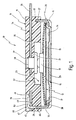
- Fig. 1 designates the new switch, which is a housing 11, in which a temperature-dependent switching mechanism 12th is arranged.
- the housing 11 comprises a conductive material, preferably Metal-made base 14 and an insulating Material manufactured lid part 15 that closes the lower part 14.
- the temperature-dependent switching mechanism 12 has in a known manner a spring washer 16 which extends in the lower part 14 at its Floor 17 is supported.
- the spring washer 16 carries a movable Contact part 18, which in the embodiment shown to the Spring washer 16 is welded.
- a bimetallic snap disk 19 slipped.
- the lower part 14 is a deep-drawn part 26 with a circumferential raised edge 27, from which up three tabs 28 extend, as well as from the top view of the lower part 14 can be seen in Fig. 2.
- a reinforcing bead 29 is provided, which is the lower part 14 gives mechanical stability.
- the new switch 10 is the cover part 15 integrally formed with a first terminal electrode 34, which includes an angled bridge 35 extending from her outer terminal part 36 to the region of a bore 37th extends, where the first mating contact 21 is arranged.
- This first mating contact 21 is seated with its bolt 38 in the bore 37, which extends through the lid part 15 and the web 35 of the first Terminal electrode 34 extends therethrough. Between the bolt 38 and the bore 37 prevails a cutting / clamping connection before, so that the bolt 38 by simply plugging in the bore 37 is securely held.
- the insulating cover part 15 has as another integral Part of a second connection electrode 41, which according to Fig. 3 comprises a ring segment 42 to which the outside Connecting part 43 connects.
- the two terminal electrodes 34 and 41 were used in the production overmolded with the cover part 15, so that they are an integral part the lid part 15 are.
- the two terminal electrodes 34 and 41 lie in a plane, which is made possible by the fact that the angled Bridge 35 in the open area of the ring segment 42nd can extend into it.
- Fig. 1 it can also be seen that the cover part 15 a circumferential annular groove 45, in which the peripheral edge 27th of the lower part 14 is located, so that the interior of the switch 10th Dustproof is completed.
- a slot 46 is further provided three times, to which another slot 47 connects, the in the ring segment 42 is provided.
- These two slots 46, 47 open into a radially outwardly and upwardly open pocket 48, in which the tab 28 protrudes from below.
- the bag 48 is at its bottom 49 an exposed area of the second Connection electrode 41 is provided, so that the bent upper End 50 of the tab 28 in abutment with the second connection electrode 41 is not just an electrical connection to the lower part 14 but at the same time also the Lid part 15 attached to the lower part 14.
- Fig. 1 it can be further seen that the pocket 48 a Wall 51 having the bent upper end 50 of the tab 28th surmounted above, so that no electrically conductive parts to survive above the new switch 10, thus after protected above from unwanted electrical contacts.
- the operation of the extent described switch 10 is as follows: In the cryogenic temperature shown in FIG an electrically conductive connection from the connecting part 36 of the first terminal electrode 34 via the first mating contact 21, the movable contact part 18, which consists of electrically conductive Material manufactured spring washer 16, the warts 31 or the Pad 30, the conductive base 14, the upstanding Tabs 28 and the ring segment 42 to the connection part 43 of second terminal electrode 41.
- the temperature increases snaps the bimetal snap disc 19 of the convex shown in a concave position and then pushes the movable Contact member 18 against the force of the spring washer 16 of the first mating contact 21 away.
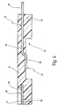
- Fig. 4 is an alternative embodiment of the cover part 15, in which instead of an insulated first mating contact 21 of the angled bridge 35 extended and on his free end 52 is angled downwards so that the first Counter contact 21, so to speak in one piece with the first connection electrode 34 is formed.
- the remaining features of the cover part 15 of FIG. 4 correspond to those of the lid part 15 Fig. 1 and are accordingly with the same reference numerals busy.
- connection electrodes 34, 41 are with their connection parts 36, 43 integrally guided on a metal strip 55, the together with the connection electrodes 34, 41 from a common Sheet metal piece 56 was punched out. There are also still transport holes 57 to recognize, over which the volume 55 in the context of a automatic production is moved.
- terminal electrodes 34, 41 become as shown in FIG. 5 shown punched out of the common sheet metal piece 56 and then overmolded with the cover part 15, so that they are integral Part of the cover part, as shown in Figs. 1 and 4 is shown.
- the lower part 14 is manufactured as a deep-drawn part, wherein in addition to the upstanding, peripheral edge 27 nor the Tabs 28 and either the warts 31 or the support bead 30th be formed in the deep drawing and previous punching.
- This lower part 14 is as bulk of an automatic Supplied to the production machine, positioned there and in pallets used. Then the tabs 28, which may be during of transport bent again.
- the spring washer is punched out of strip material, bent, heat treated and with a contact part 18 which is either welded or stamped.
- the bimetallic snap disk is also called the bulk material fed to automatic manufacturing machine.
- the bimetallic snap-action disc is being produced by the production automaton 19 slipped over the contact part 18 whose position because the warts 31 is well known and securely fixed.
Landscapes
- Physics & Mathematics (AREA)
- Thermal Sciences (AREA)
- Engineering & Computer Science (AREA)
- Manufacturing & Machinery (AREA)
- Thermally Actuated Switches (AREA)
- Slide Switches (AREA)
- Switches With Compound Operations (AREA)
- Circuit Arrangements For Discharge Lamps (AREA)
- Switch Cases, Indication, And Locking (AREA)
- Fire-Detection Mechanisms (AREA)
- Amplifiers (AREA)
- Addition Polymer Or Copolymer, Post-Treatments, Or Chemical Modifications (AREA)
- Manufacture Of Switches (AREA)
Abstract
Description
- Ausstanzen der beiden Anschlusselektroden aus einem gemeinsamen Blechstück und
- Umspritzen der Anschlusselektroden mit dem Deckelteil.
- Tiefziehen des Unterteiles derart, dass es in Richtung des aufzusetzenden Deckelteiles hochstehende Laschen aufweist.
- Einstecken des ersten Gegenkontaktes mit seinem Bolzen von der Innenseite des Deckelteiles her in eine durch das Deckelteil und die erste Anschlusselektrode hindurchgehende Bohrung, wobei der Bolzen durch eine Schneid-/Klemmverbindung an der ersten Anschlusselektrode befestigt wird.
- Versehen des Unterteiles an seinem Boden mit radial außen liegenden und umfänglich verteilt angeordneten Warzen als Auflage für das Schaltwerk.
- Fig. 1
- einen Längsschnitt durch den neuen Schalter;
- Fig. 2
- eine Draufsicht auf ein weiteres Ausführungsbeispiel des Unterteiles des Schalters aus Fig. 1;
- Fig. 3
- eine Draufsicht auf das Deckelteil bei dem Schalter aus Fig. 1;
- Fig. 4
- einen Längsschnitt durch ein weiteres Ausführungsbeispiel des Deckelteiles des Schalters aus Fig. 1; und
- Fig. 5
- die bei dem neuen Schalter aus Fig. 1 verwendeten Anschlusselektroden, wie sie am Band vor der Umspritzung mit dem Deckelteil angeliefert werden.
Claims (25)
- Schalter mit einem ein temperaturabhängiges Schaltwerk (12) aufnehmenden Gehäuse (11), das ein elektrisch leitendes Unterteil (14) sowie ein das Unterteil (14) verschließendes und daran befestigtes, elektrisch isolierendes Deckelteil (15) umfasst, an dessen Innenseite (22) ein erster, nach außen durchkontaktierter Gegenkontakt (21) für das Schaltwerk (12) vorgesehen ist, wobei das Unterteil (14) als zweiter Gegenkontakt (24) des Schaltwerkes (12) dient, das in Abhängigkeit von seiner Temperatur eine elektrisch leitende Verbindung zwischen den beiden Gegenkontakten (21, 24) herstellt, bei dem an dem Deckelteil (15) eine erste Anschlusselektrode (34) unverlierbar angeordnet ist, die elektrisch mit dem ersten Gegenkontakt (21) verbunden ist, sowie eine zweite Anschlusselektrode (41) unverlierbar angeordnet ist, die infolge der Befestigung des Deckelteiles (15) an dem Unterteil (14) elektrisch mit dem Unterteil (14) verbunden ist,
dadurch gekennzeichnet, dass an dem Unterteil (14) nach oben weisende, umgebogene Laschen (28) vorgesehen sind, die das Deckelteil (15) halten und die zweite Anschlusselektrode (41) kontaktieren. - Schalter nach Anspruch 1, dadurch gekennzeichnet, dass die zweite Anschlusselektrode (41) in dem Deckelteil (15) als Ringsegment (42) ausgebildet ist, in das sich die erste Anschlusselektrode (34) hineinerstreckt.
- Schalter nach Anspruch 1 oder 2, dadurch gekennzeichnet, dass die erste Anschlusselektrode (34) mit dem Deckelteil (15) derart umspritzt oder vergossen ist, dass sie integraler Bestandteil des Deckelteiles (15) ist, und mit einem Anschlussteil (36) aus dem Deckelteil (15) hervorsteht.
- Schalter nach einem der Ansprüche 1 bis 3, dadurch gekennzeichnet, dass die zweite Anschlusselektrode (41) mit dem Deckelteil (15) derart umspritzt oder vergossen ist, dass sie integraler Bestandteil des Deckelteiles (15) ist, und mit einem Anschlussteil (43) aus dem Deckelteil (15) hervorsteht.
- Schalter nach einem der Ansprüche 1 bis 4, dadurch gekennzeichnet, dass die erste Anschlusselektrode (34) sich in dem Deckelteil (15) als Steg (35) von ihrem Anschlussteil (36) zu dem etwa zentrisch angeordneten ersten Gegenkontakt (41) erstreckt.
- Schalter nach einem der Ansprüche 1 bis 5, dadurch gekennzeichnet, dass die erste und die zweite Anschlusselektrode (34, 41) aus einem gemeinsamen Blechteil (56) ausgestanzt sind.
- Schalter nach einem der Ansprüche 1 bis 6, dadurch gekennzeichnet, dass das Unterteil (14) ein Tiefziehteil (26) mit einem umlaufenden Rand (27) ist, der in eine Ringnut (45) in dem Deckelteil (15) eingreift.
- Schalter nach einem der Ansprüche 1 bis 7, dadurch gekennzeichnet, dass das Deckelteil (15) und ggf. die zweite Anschlusselektrode (41) Schlitze (46, 47) für die Laschen (28) aufweisen.
- Schalter nach Anspruch 8, dadurch gekennzeichnet, dass das Deckelteil (15) das Unterteil (14) übergreift und nach oben sowie radial nach außen offene Taschen (48) aufweist, in deren Boden (49) die Schlitze (46, 47) münden, und an deren Boden (49) die zweite Anschlusselektrode (41) für die Laschen (28) zugänglich ist.
- Schalter nach Anspruch 9, dadurch gekennzeichnet, dass Wände (51) der Taschen (48) über die umgebogenen Laschen (28) nach oben vorstehen.
- Schalter nach einem der Ansprüche 5 bis 10, dadurch gekennzeichnet, dass der erste Gegenkontakt (21) als nach unten gebogenes, abgewinkeltes freies Ende (52) der stegartig ausgebildeten ersten Anschlusselektrode (34) ausgebildet ist.
- Schalter nach einem der Ansprüche 5 bis 10, dadurch gekennzeichnet, dass der erste Gegenkontakt (21) einen Bolzen (38) aufweist, der von der Innenseite (22) her in einer zentrischen Bohrung (37) in dem Deckelteil (15) sowie dem ersten Anschlussteil (34) steckt und an der ersten Anschlusselektrode (34) durch eine Schneid-/Klemmverbindung gehalten ist.
- Schalter nach einem der Ansprüche 1 bis 12, dadurch gekennzeichnet, dass das Schaltwerk (12) eine gegen eine Bimetall-Schnappscheibe (19) arbeitende Federscheibe (16) umfasst, die sich mit ihrem Rand (32) am Unterteil (14) abstützt und ein bewegliches Kontaktteil (18) trägt, das sie unterhalb einer Schalttemperatur des Schaltwerkes (12) gegen den ersten Gegenkontakt (21) drückt.
- Schalter nach Anspruch 13, dadurch gekennzeichnet, dass das bewegliche Kontaktteil (18) unverlierbar an der Federscheibe (16) gehalten ist.
- Schalter nach Anspruch 14, dadurch gekennzeichnet, dass das bewegliche Kontaktteil (18) an die Federscheibe (16) angeschweißt ist.
- Schalter nach Anspruch 14, dadurch gekennzeichnet, dass das bewegliche Kontaktteil (18) einstückig mit der Federscheibe (16) ausgebildet ist.
- Schalter nach einem der Ansprüche 13 bis 16, dadurch gekennzeichnet, dass das Unterteil (14) an seinem Boden (17) radial außen liegende und umfänglich verteilt angeordnete Warzen (31) als Auflage für den Rand (32) der Federscheibe (16) aufweist.
- Schalter nach Anspruch 17, dadurch gekennzeichnet, dass drei Warzen (31) vorgesehen sind, die umfänglich etwa gleich verteilt sind.
- Verfahren zur Fertigung eines Schalters (10) mit einem ein temperaturabhängiges Schaltwerk (12) aufnehmenden Gehäuse (11), mit den Schritten:a) Bereitstellen eines elektrisch isolierenden Deckelteiles (15), an dem zwei Anschlusselektroden (34, 41) unverlierbar angeordnet sind, wobei die erste Anschlusselektrode (34) nach außen durchkontaktiert und elektrisch mit einem an dem Deckelteil (15) an dessen Innenseite (22) vorgesehenen ersten Gegenkontakt (21) für das Schaltwerk (12) verbunden ist,b) Bereitstellen eines Unterteiles (14) aus elektrisch leitfähigem Material,c) Einlegen des Schaltwerkes (12) in das Unterteil (14),d) Verschließen des Unterteiles (14) mit dem Deckelteil (15), unde) Befestigen des Deckelteiles (15) an dem Unterteil (14), wodurch gleichzeitig eine elektrische Verbindung zwischen der zweiten Anschlusselektrode (41) und dem Unterteil (14) hergestellt wird, das als zweiter Gegenkontakt (24) für das Schaltwerk (12) dient.
- Verfahren nach Anspruch 19, dadurch gekennzeichnet, dass Schritt a) die folgenden Unterschritte aufweist:Ausstanzen der beiden Anschlusselektroden (34, 41) aus einem gemeinsamen Blechstück (56), undUmspritzen der Anschlusselektroden (34, 41) mit dem Deckelteil (15).
- Verfahren nach Anspruch 20, dadurch gekennzeichnet, dass der Schritt a) den weiteren Unterschritt aufweist:Einstecken des ersten Gegenkontaktes (21) mit seinem Bolzen (38) von der Innenseite (22) her in eine durch das Deckelteil (15) und die erste Anschlusselektrode (34) hindurchgehende Bohrung (37), wobei der Bolzen (38) durch eine Schneid-/Klemmverbindung an der ersten Anschlusselektrode (34) befestigt wird.
- Verfahren nach einem der Ansprüche 19 bis 21, dadurch gekennzeichnet, dass der Schritt b) den folgenden Unterschritt aufweist:Tiefziehen des Unterteiles (14) derart, dass es in Richtung des aufzusetzenden Deckelteiles (15) hochstehende Laschen (28) aufweist.
- Verfahren nach einem der Ansprüche 19 bis 22, dadurch gekennzeichnet, dass der Schritt b) den Unterschritt aufweist:Versehen des Unterteiles (14) an seinem Boden (17) mit radial außen liegenden und umfänglich verteilt angeordneten Warzen (31) als Auflage für das Schaltwerk (12).
- Verfahren nach einem der Ansprüche 19 bis 23, dadurch gekennzeichnet, dass im Schritt d) das Deckelteil (15) derart auf das Unterteil (14) aufgesetzt wird, dass Laschen (28) des Unterteiles (14) durch Schlitze (46, 47) des Deckelteiles (15) und ggf. der ersten Anschlusselektrode (34) hindurchgesteckt werden.
- Verfahren nach Anspruch 24, dadurch gekennzeichnet, dass im Schritt e) die Laschen (28) derart umgebogen werden, dass sie in nach oben sowie radial nach außen offenen Taschen (28) des Deckelteiles (15) zum Liegen kommen und dort freie Bereiche der zweiten Anschlusselektrode (41) kontaktieren und gleichzeitig das Deckelteil (15) an dem Unterteil (14) befestigen.
Applications Claiming Priority (3)
| Application Number | Priority Date | Filing Date | Title |
|---|---|---|---|
| DE19609577 | 1996-03-12 | ||
| DE19609577A DE19609577C2 (de) | 1996-03-12 | 1996-03-12 | Schalter mit einem temperaturabhängigen Schaltwerk |
| EP97100311A EP0795885B1 (de) | 1996-03-12 | 1997-01-10 | Schalter mit einem temperaturabhängigen Schaltwerk |
Related Parent Applications (1)
| Application Number | Title | Priority Date | Filing Date |
|---|---|---|---|
| EP97100311A Division EP0795885B1 (de) | 1996-03-12 | 1997-01-10 | Schalter mit einem temperaturabhängigen Schaltwerk |
Publications (2)
| Publication Number | Publication Date |
|---|---|
| EP1536445A2 true EP1536445A2 (de) | 2005-06-01 |
| EP1536445A3 EP1536445A3 (de) | 2006-05-03 |
Family
ID=7787987
Family Applications (2)
| Application Number | Title | Priority Date | Filing Date |
|---|---|---|---|
| EP05004787A Withdrawn EP1536445A3 (de) | 1996-03-12 | 1997-01-10 | Schalter mit einem temperaturabhängigen Schaltwerk |
| EP97100311A Expired - Lifetime EP0795885B1 (de) | 1996-03-12 | 1997-01-10 | Schalter mit einem temperaturabhängigen Schaltwerk |
Family Applications After (1)
| Application Number | Title | Priority Date | Filing Date |
|---|---|---|---|
| EP97100311A Expired - Lifetime EP0795885B1 (de) | 1996-03-12 | 1997-01-10 | Schalter mit einem temperaturabhängigen Schaltwerk |
Country Status (6)
| Country | Link |
|---|---|
| US (1) | US5867085A (de) |
| EP (2) | EP1536445A3 (de) |
| AT (1) | ATE294995T1 (de) |
| DE (2) | DE19609577C2 (de) |
| ES (1) | ES2241010T3 (de) |
| PT (1) | PT795885E (de) |
Families Citing this family (20)
| Publication number | Priority date | Publication date | Assignee | Title |
|---|---|---|---|---|
| AUPS199902A0 (en) * | 2002-04-19 | 2002-06-06 | F F Seeley Nominees Pty Ltd | Protector for thermal switch installed in electromagnetic coils |
| US20070173423A1 (en) * | 2004-06-29 | 2007-07-26 | Vermeer Robert C | Method and device for fragrancing and fabric treatment in a clothes dryer |
| DE102005001371B4 (de) * | 2005-01-12 | 2012-03-15 | Marcel P. HOFSAESS | Verwendung eines Anschlussübertopfes sowie Schalter mit einem Anschlussübertopf |
| CN100446148C (zh) * | 2005-11-07 | 2008-12-24 | 徐佳义 | 手动复位温控器 |
| US8076813B2 (en) * | 2006-06-21 | 2011-12-13 | Emerson Electric Co. | Hermetic motors with windings coupled to on-winding motor protectors via welded terminals |
| EP2038905B1 (de) | 2006-07-11 | 2010-09-22 | Thermik Gerätebau GmbH | Anschlussübertopf und schalter mit anschlussübertopf |
| GB2481240B (en) * | 2010-06-17 | 2017-04-12 | Otter Controls Ltd | Thermally responsive electric switches |
| DE102011015116A1 (de) * | 2011-03-22 | 2012-09-27 | Marcel P. HOFSAESS | Verfahren zur Herstellung eines temperaturabhängigen Schalters |
| DE102011107110B4 (de) * | 2011-07-12 | 2013-04-18 | Marcel P. HOFSAESS | Verfahren zum Umgeben eines elektrischen Bauteils mit einem Schutzgehäuse sowie elektrisches Bauteil mit einem Schutzgehäuse |
| TWI594284B (zh) * | 2011-10-20 | 2017-08-01 | 太谷電子日本合同公司 | 保護裝置及保護裝置的製造方法 |
| DE102011119632B3 (de) * | 2011-11-22 | 2013-04-11 | Marcel P. HOFSAESS | Temperaturabhängiges Schaltwerk |
| US9048048B2 (en) * | 2012-08-16 | 2015-06-02 | Uchiya Thermostat Co., Ltd. | Thermal protector |
| DE102013101393B4 (de) * | 2013-02-13 | 2014-10-09 | Thermik Gerätebau GmbH | Temperaturabhängiger Schalter |
| EP2988313B2 (de) * | 2013-04-19 | 2023-03-29 | Littelfuse Japan G.K. | Schutzvorrichtung |
| WO2015029826A1 (ja) * | 2013-08-26 | 2015-03-05 | タイコエレクトロニクスジャパン合同会社 | 保護装置 |
| DE102015114248B4 (de) * | 2015-08-27 | 2019-01-17 | Marcel P. HOFSAESS | Temperaturabhängiger Schalter mit Schneidgrat |
| DE102022120445B3 (de) * | 2022-08-12 | 2023-11-30 | Marcel P. HOFSAESS | Temperaturabhängiger Schalter |
| DE102022120446B3 (de) | 2022-08-12 | 2023-11-30 | Marcel P. HOFSAESS | Temperaturabhängiger Schalter |
| DE102023102302B3 (de) | 2023-01-31 | 2024-03-28 | Marcel P. HOFSAESS | Temperaturabhängiger Schalter |
| DE102023102304B4 (de) * | 2023-01-31 | 2024-08-08 | Marcel P. HOFSAESS | Temperaturabhängiges Schaltwerk und temperaturabhängiger Schalter |
Family Cites Families (11)
| Publication number | Priority date | Publication date | Assignee | Title |
|---|---|---|---|---|
| DE1515463A1 (de) * | 1965-03-09 | 1969-06-26 | Busch Jaeger Duerener Metall | Befestigung einer metallischen Kappe oder Haube an einem Isolierstoffsockel |
| DE2121802C3 (de) * | 1971-05-03 | 1974-10-24 | Thermik-Geraetebau Gmbh + Co, 7530 Pforzheim | Temperaturwächter |
| DE3122899C2 (de) * | 1981-06-10 | 1984-10-11 | Peter 7530 Pforzheim Hofsäss | Temperaturschalter |
| US4710743A (en) * | 1985-12-04 | 1987-12-01 | Portage Electric Products, Inc. | Thermostatic device with leak tight casing |
| GB2239827B (en) * | 1986-12-18 | 1991-10-16 | Electrovac | Method for joining conductor parts of an electric switch component |
| DE3710672C2 (de) * | 1987-03-31 | 1997-05-15 | Hofsaes Geb Zeitz Ulrika | Temperaturwächter mit einem Gehäuse |
| DE8908999U1 (de) * | 1989-07-25 | 1990-08-23 | Hofsäss, Peter, 7530 Pforzheim | Temperaturschalter mit Bimetall-Schaltwerk |
| DE8915123U1 (de) * | 1989-12-23 | 1990-08-23 | Hofsäss, Peter, 75181 Pforzheim | Temperaturschalter |
| EP0410119B1 (de) * | 1989-07-25 | 1995-10-18 | Hofsäss, Ulrika | Temperaturschalter mit Bimetall-Schaltwerk |
| DE4139091C2 (de) * | 1991-11-28 | 2002-02-07 | Hofsaes Geb Zeitz | Temperaturschalter in einem dichten Gehäuse |
| DE4317360A1 (de) * | 1993-05-25 | 1994-12-01 | Wahler Gmbh & Co Gustav | Temperaturabhängiges Schaltgerät |
-
1996
- 1996-03-12 DE DE19609577A patent/DE19609577C2/de not_active Expired - Fee Related
-
1997
- 1997-01-10 PT PT97100311T patent/PT795885E/pt unknown
- 1997-01-10 EP EP05004787A patent/EP1536445A3/de not_active Withdrawn
- 1997-01-10 DE DE59712290T patent/DE59712290D1/de not_active Expired - Fee Related
- 1997-01-10 AT AT97100311T patent/ATE294995T1/de not_active IP Right Cessation
- 1997-01-10 EP EP97100311A patent/EP0795885B1/de not_active Expired - Lifetime
- 1997-01-10 ES ES97100311T patent/ES2241010T3/es not_active Expired - Lifetime
- 1997-03-03 US US08/808,488 patent/US5867085A/en not_active Expired - Fee Related
Also Published As
| Publication number | Publication date |
|---|---|
| DE59712290D1 (de) | 2005-06-09 |
| EP1536445A3 (de) | 2006-05-03 |
| DE19609577A1 (de) | 1997-09-18 |
| ES2241010T3 (es) | 2005-10-16 |
| EP0795885B1 (de) | 2005-05-04 |
| ATE294995T1 (de) | 2005-05-15 |
| EP0795885A2 (de) | 1997-09-17 |
| EP0795885A3 (de) | 1998-11-18 |
| PT795885E (pt) | 2005-07-29 |
| DE19609577C2 (de) | 1998-02-19 |
| US5867085A (en) | 1999-02-02 |
Similar Documents
| Publication | Publication Date | Title |
|---|---|---|
| EP0795885B1 (de) | Schalter mit einem temperaturabhängigen Schaltwerk | |
| DE102008048554B3 (de) | Temperaturabhängiger Schalter | |
| DE4337141C2 (de) | Temperaturabhängiger Schalter | |
| DE19708436C2 (de) | Temperaturabhängiger Schalter mit Kontaktbrücke und Verfahren zu dessen Herstellung | |
| EP0794546B1 (de) | Schalter mit einem temperaturabhängigen Schaltwerk | |
| EP0887826A2 (de) | Temperaturabhängiger Schalter mit Kontaktbrücke | |
| EP0858090B1 (de) | Temperaturabhängiger Schalter mit einem Bimetall-Schaltwerk | |
| EP2783380B1 (de) | Temperaturabhängiges schaltwerk | |
| EP0678882B1 (de) | Elektrischer Schalter und Herstellverfahren für einen derartigen Schalter | |
| EP3796360B1 (de) | Temperaturabhängiger schalter | |
| EP0778599B1 (de) | Schalter mit einem temperaturabhängigen Schaltwerk | |
| EP0887827B1 (de) | Schalter mit einem temperatur-abhängigen Schaltwerk | |
| EP2038905B1 (de) | Anschlussübertopf und schalter mit anschlussübertopf | |
| DE102015110509B4 (de) | Temperaturabhängiger Schalter mit lsolierscheibe und elektronische Schaltung mit einemauf einer Leiterplatte montierten, temperaturabhängigen Schalter | |
| DE19705410A1 (de) | Temperaturabhängiger Schalter mit Haltebügel | |
| DE102005001371B4 (de) | Verwendung eines Anschlussübertopfes sowie Schalter mit einem Anschlussübertopf | |
| EP3270401B1 (de) | Temperaturabhängiger schalter mit isolierscheibe | |
| EP4528772B1 (de) | Temperaturabhängiges schaltwerk und temperaturabhängiger schalter | |
| DE102023005419A1 (de) | Temperaturabhängiges Schaltwerk und temperaturabhängiger Schalter | |
| DE2513011A1 (de) | Elektrischer schnappschalter, insbesondere kleinschalter |
Legal Events
| Date | Code | Title | Description |
|---|---|---|---|
| PUAI | Public reference made under article 153(3) epc to a published international application that has entered the european phase |
Free format text: ORIGINAL CODE: 0009012 |
|
| AC | Divisional application: reference to earlier application |
Ref document number: 0795885 Country of ref document: EP Kind code of ref document: P |
|
| AK | Designated contracting states |
Kind code of ref document: A2 Designated state(s): AT BE CH DE ES FR GB IT LI NL PT |
|
| PUAL | Search report despatched |
Free format text: ORIGINAL CODE: 0009013 |
|
| AK | Designated contracting states |
Kind code of ref document: A3 Designated state(s): AT BE CH DE ES FR GB IT LI NL PT |
|
| 17P | Request for examination filed |
Effective date: 20060906 |
|
| AKX | Designation fees paid |
Designated state(s): AT BE CH DE ES FR GB IT LI NL PT |
|
| RIN1 | Information on inventor provided before grant (corrected) |
Inventor name: HOFSAESS, MARCEL P. Inventor name: KRUCK, GUENTER |
|
| STAA | Information on the status of an ep patent application or granted ep patent |
Free format text: STATUS: THE APPLICATION HAS BEEN WITHDRAWN |
|
| 18W | Application withdrawn |
Effective date: 20100318 |