EP1536595B1 - Procédé pour implanter un module de gestion dans l'électronique automobile - Google Patents
Procédé pour implanter un module de gestion dans l'électronique automobile Download PDFInfo
- Publication number
- EP1536595B1 EP1536595B1 EP03027509A EP03027509A EP1536595B1 EP 1536595 B1 EP1536595 B1 EP 1536595B1 EP 03027509 A EP03027509 A EP 03027509A EP 03027509 A EP03027509 A EP 03027509A EP 1536595 B1 EP1536595 B1 EP 1536595B1
- Authority
- EP
- European Patent Office
- Prior art keywords
- driver module
- electrical devices
- electrical
- signal
- driver
- Prior art date
- Legal status (The legal status is an assumption and is not a legal conclusion. Google has not performed a legal analysis and makes no representation as to the accuracy of the status listed.)
- Expired - Lifetime
Links
- 238000000034 method Methods 0.000 title claims description 23
- 230000004044 response Effects 0.000 claims description 30
- 238000012360 testing method Methods 0.000 claims description 16
- 238000005259 measurement Methods 0.000 claims description 3
- 230000036962 time dependent Effects 0.000 claims 2
- 230000006870 function Effects 0.000 description 26
- 238000011156 evaluation Methods 0.000 description 11
- 238000001514 detection method Methods 0.000 description 6
- 230000001939 inductive effect Effects 0.000 description 5
- 239000003990 capacitor Substances 0.000 description 3
- 238000004891 communication Methods 0.000 description 3
- 238000010276 construction Methods 0.000 description 3
- 230000004069 differentiation Effects 0.000 description 2
- 230000010354 integration Effects 0.000 description 2
- 230000015572 biosynthetic process Effects 0.000 description 1
- 230000008859 change Effects 0.000 description 1
- 238000006243 chemical reaction Methods 0.000 description 1
- 239000003086 colorant Substances 0.000 description 1
- 238000013461 design Methods 0.000 description 1
- 238000011161 development Methods 0.000 description 1
- 230000018109 developmental process Effects 0.000 description 1
- 230000000694 effects Effects 0.000 description 1
- 238000002474 experimental method Methods 0.000 description 1
- 238000009434 installation Methods 0.000 description 1
- 238000003909 pattern recognition Methods 0.000 description 1
- 230000008569 process Effects 0.000 description 1
- 230000008439 repair process Effects 0.000 description 1
- 230000002123 temporal effect Effects 0.000 description 1
- 230000001052 transient effect Effects 0.000 description 1
Images

Classifications
-
- H—ELECTRICITY
- H04—ELECTRIC COMMUNICATION TECHNIQUE
- H04L—TRANSMISSION OF DIGITAL INFORMATION, e.g. TELEGRAPHIC COMMUNICATION
- H04L12/00—Data switching networks
- H04L12/28—Data switching networks characterised by path configuration, e.g. LAN [Local Area Networks] or WAN [Wide Area Networks]
- H04L12/40—Bus networks
- H04L12/40006—Architecture of a communication node
- H04L12/40032—Details regarding a bus interface enhancer
-
- H—ELECTRICITY
- H04—ELECTRIC COMMUNICATION TECHNIQUE
- H04L—TRANSMISSION OF DIGITAL INFORMATION, e.g. TELEGRAPHIC COMMUNICATION
- H04L12/00—Data switching networks
- H04L12/28—Data switching networks characterised by path configuration, e.g. LAN [Local Area Networks] or WAN [Wide Area Networks]
- H04L12/40—Bus networks
- H04L2012/40267—Bus for use in transportation systems
- H04L2012/40273—Bus for use in transportation systems the transportation system being a vehicle
-
- H—ELECTRICITY
- H04—ELECTRIC COMMUNICATION TECHNIQUE
- H04L—TRANSMISSION OF DIGITAL INFORMATION, e.g. TELEGRAPHIC COMMUNICATION
- H04L43/00—Arrangements for monitoring or testing data switching networks
- H04L43/50—Testing arrangements
Definitions
- the present invention relates to a method for incorporating a driver module in a motor vehicle electrical system.
- motor vehicle electrical systems Electrical systems of motor vehicles, hereinafter referred to as motor vehicle electrical systems, often have a central control unit which activates driver modules of the motor vehicle electrical system, which in turn operate on these connected electrical devices, for example consumers or loads or sensors.
- the driver modules for the corresponding electrical devices are fixed and are connected to them via cables that have a coding on colors or connectors used to prevent incorrect connection of electrical equipment to the driver modules.
- the driver modules are designed according to their function or the devices connected to them, so that various driver modules are installed in a motor vehicle electrical system. Accordingly, the driver modules are not arbitrarily connected to the central control unit, so that even for the connection to the motor vehicle electrical codes may be necessary.
- US 6,249,060 B1 describes a multiplexing system for a vehicle for controlling electrically operated components.
- the system has an integrated power and communication bus to provide power and commands to vehicle components, multiplexing devices to send multiple commands over two or more buses, a control processor circuit to control operation, a wiring harness with interface connections for electrically powered components, and Selectable communication bandwidths for adapting the components and bandwidths to each other.
- DE 102 03 341-A1 an electronic control unit for a motor vehicle or a vehicle drive unit is described, which is connected via connectors provided with cables with several electrical or electronic components and in which after a first connection of a plug with a specific component, a learning function expires. Based on the learning function is detected and stored in the control unit, which specific type of various possible components is connected to the respective connector. As part of the learning function, the respective component is activated and closed on the basis of the signals of a sensor recording this activity on the specific type of this device.
- EP 791 506 A2 describes an electrical system having central control connected to intelligent nodes via multiplex connections.
- the nodes are programmed with predetermined instruction sets necessary to operate loads connected to the nodes.
- the central controller may issue high-level commands to the intelligent nodes via a serial data communication bus to complete the execution of the predetermined programmed ones Initiate instruction sets in the intelligent nodes.
- the nodes in turn operate the electrical loads of the system.
- the present invention is therefore based on the object to provide a method for the integration of driver modules in a motor vehicle electrical system, which allows a simple construction of a motor vehicle electrical system and a simple installation thereof.
- the control unit for operating the electrical devices via these associated signal channels signals to and / or transmitted from the driver module or receives a connection pattern of the driver module is determined, which is given at least by the types of electrical devices connected to the driver module and their respective number, and the determined connection pattern with predetermined connection patterns for possibly occurring in the automotive electrics driver modules with connected electrical devices, each of which at least one parameter for operating the driver module and / or or the electrical equipment connected thereto is assigned.
- at least one parameter is assigned to the driver module and / or signal channels and electrical devices connected to the driver module are assigned to one another.
- the method according to the invention is therefore used for motor vehicle electrics which comprise a control unit, at least one driver module connected to the control unit via signal channels and electrical devices connected to outputs and / or inputs of the driver module.
- a plurality of corresponding driver modules with electrical devices connected thereto are connected to the control unit.
- the electrical devices can be basically arbitrary, but for a given automotive electrical certain types are given, so that connection patterns can be determined.
- the types do not necessarily need to be products of different manufacturers. Rather, the nature of the electrical device and its possible function in the automotive electrical system and in their operation to be considered conditions may be of importance.
- the types can be selected such that, knowing the type, operating parameters for the electrical devices can be determined and, if necessary, set.
- the types are preferably chosen so that they can be automatically determined in an automatic configuration of the driver module. In particular, therefore, the type can be made according to electrical characteristics of the electrical equipment.
- electrical devices are, for example, electrical loads or consumers such as lamps or motors or sensors into consideration.
- the driver module can have a plurality of drivers, which are understood as meaning any devices that are suitable for operating the electrical devices in a motor vehicle electrical system.
- the drivers may include load switches with which these connected loads or loads can be switched on or off in response to corresponding control signals.
- drivers for sensors can also be used.
- the signal channels between the control unit and the driver module may be in the form of separate lines or preferably as channels in a bus system.
- control unit During normal operation, the control unit emits a control signal via a signal channel assigned to an electrical device to the corresponding driver module, which is supplied there to the corresponding driver, which then controls the electrical device accordingly.
- signals from the driver modules which may have been detected there, for example, by the electrical devices connected thereto, can also be transmitted to the control unit via the signal channels.
- a connection pattern of the driver module is determined, which is given at least by the types of electrical devices connected to the driver module and their respective numbers. This step is based on the assumption that driver modules in such a motor vehicle electrical system can be identified by the electrical devices connected to them or their types, and more particularly the connection pattern.
- the determined connection pattern is then compared with predetermined connection patterns for driver modules in the automotive electrical system.
- the predetermined connection patterns result from the possible with the correct construction of the motor vehicle electrical connection patterns of electrical equipment to the corresponding, in the automotive electrical system included driver modules.
- Such predetermined connection patterns can be stored in particular in the control unit, wherein connection patterns for other motor vehicle electrics in which the control unit is used can also be stored in the corresponding memory.
- Each of these predetermined connection patterns is assigned at least one parameter for operating the driver module corresponding to the connection pattern and / or the electrical devices connected thereto.
- the driver module is identified, so that at least one correspondingly determined parameter for the driver module can be assigned to the driver module.
- an assignment of signal channels and driver modules or electrical devices connected to them can take place automatically, so that the use of coded cables or cable harnesses for connecting the central control unit and the driver modules is not necessary.
- a driver module of the motor vehicle electrical system can be automatically detected together with the electrical devices connected thereto and set up or configured for operation in the motor vehicle electrical system in accordance with the electrical devices connected to it easily and without any considerable effort.
- connection patterns In principle, it suffices for the connection patterns to comprise only the various types of electrical devices connected to the driver module and their respective numbers. In order to enable unambiguous identification of the driver modules, even if consumers of the same type but different functions, for example right and left turn signal bulbs, are connected to one and the same driver module, it is preferred for the connection pattern additionally to contain information about it. which determined type of electrical device is connected to which output and / or input of the driver module. In particular, the connection pattern can contain, for example, the determined types in the order of the outputs and / or inputs of the driver module to which they are connected.
- the driver module not only determines the types of electrical equipment connected to this, but also assigns these signal channels, for example in a bus.
- the control unit can then take over this assignment.
- given signal channels are assigned to the electrical devices on the basis of the parameters associated with the connection pattern determined by the comparison.
- the parameters assigned to a given connection pattern can in particular include identifiers of the signal channels that are predetermined for predetermined functions and the electrical equipment required for them. This assignment can be made in particular in the driver module.
- a plurality of identical driver modules connected to the control unit be configurable for operating at least some of the electrical devices and automatically configured according to the electrical devices connected to them ,
- the configuration can be wholly or partly done in the driver modules, but the corresponding parameters are preferably at least partially set by the control unit or transmitted to the driver modules.
- connection pattern of the driver module it is sufficient for the connection pattern of the driver module to be stored, for example, in the driver module and to be retrievable by the control unit for determining the connection pattern.
- the types of the electrical devices connected to the driver module are determined by determining predetermined electrical test signals for the input pattern or outputs, Response signals are detected which represent the responses of the electrical devices to the respective test signals, and for determining predetermined types of the connected electrical devices from the response signals determined data with corresponding predetermined reference data for possible predetermined types of electrical equipment, for which the driver module is provided be compared.
- the reference data can be specified by specifications or determined by experiments with the test signals used. Preferably, they are chosen so that the best possible differentiation between types is possible.
- the test signals may be from a test signal generator in the driver module or from drivers in the driver module be delivered. The delivery can take place parallel or temporally staggered for the connected devices.
- a current signal and / or a voltage signal is used as the response signal, which reproduces the current to or the voltage at the respective electrical device.
- the electrical equipment need not have additional components that are solely for the identification of the same. Rather, only their electrical properties in relation to the already existing inputs and outputs can be used.
- At least one driver of the driver module as a load switch has a MOSFET device with current measurement, which outputs a current signal corresponding to the load current, and that a voltage signal generated by the current signal to a resistive element is used as the response signal.
- MOSFET devices with current measurement or current detection allow a particularly simple formation of the response signals that reflect the responses of the electrical equipment in the form of load currents, without significant additional circuitry.
- the response signal only needs to use its amplitude in the steady state.
- a chronological course of at least one response signal is detected after an initial time specified by the respective test signal, and that the type of the respective electrical device is determined on the basis of at least the chronological progression.
- jump signals are used as test signals.
- the responses to such jump signals depend on all the electrical parameters of most of the electrical devices, and therefore readily allow for discrimination between different types.
- the test signal is generated by switching on or off a corresponding electrical device.
- the jump signal can be obtained solely by a process which can be carried out anyway by the driver module, so that substantially no additional devices are required for generating the test signals.
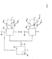
- a motor vehicle electrical system comprises a central control unit 10, which are connected via a bus 12 with driver modules 14 1 to 14 m to the loads or loads 16 11 to 16 1n to 16 m1 to 16 mn .
- m and n are natural numbers preferably greater than 1. It was only assumed for ease of description that are connected to all driver modules in each case the same number n of loads.
- the central control unit 10 and the driver modules 14 1 to 14 m are supplied via a common voltage source 18, in the example a motor vehicle battery, whose negative pole is grounded.
- the central control unit 10 serves to operate the electrical devices connected to the driver modules 14 1 to 14 m by driving the driver modules 14 1 to 14 m in response to the actuation of switches, not shown in the figures, connected to the central control unit.
- the central control unit 10 has a corresponding microcontroller and non-volatile and rewritable memory.
- the central control unit is used for the integration of the driver modules 14 1 to 14 m in the automotive electrical system, including to a corresponding programming of the microprocessor for performing the method described below has a memory 20.
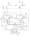
- the driver modules 14 1 to 14 m have the same design, so that their structure and function can be described using the example of the driver module 14 1 , which is shown in greater detail in FIG. 2.
- the driver module 14 1 comprises a control and evaluation device 22, and n is formed, configurable drive circuits 24 1 to 24 n, which outputs 26 11 to 26 1n, different to each other, electrical of the driver module 14 1 to be operated devices, ie Here consumers or loads 16 11 to 16 1n , are connected.
- driver circuit 24 1 to 24 n are each formed the same, so that their structure is explained using the example of the driver circuit 24 1 .
- the driver circuit 24 1 comprises, as a load switch, an n-channel MOSFET component 32 in a so-called "high-side" arrangement, in which its drain terminal 34 connects to the positive terminal of the voltage source 18 and its source terminal 36 to the output 26 11 and thus the load 16 11 is connected.
- the respective other terminal of the load 16 11 is grounded, with the negative terminal of the voltage source 18 is connected.
- the gate terminal 38 of the MOSFET device 32 is connected to a corresponding switching signal output of the control and evaluation device 22.
- the MOSFET device 32 further has a current measuring function ("current sense" function). Via a current signal output 40, a current signal is applied to a current signal branch 42 with a grounded resistor R arranged therein, the current intensity of which corresponds to the magnitude of the load current conducted through the MOSFET component 24 between the drain and source terminals 34 and 36 ,
- the MOSFET components 32 of the driver circuits 24 1 to 24 n which are respectively connected to this load switch 16 11 to 16 1n can be switched on and off by means of the load acting as load switches become.
- the control and evaluation device 22 has, in FIG. 2 only roughly schematically indicated by corresponding blocks, a first memory device 48 in the form of an EEPROM, a second memory device 50 with a nonvolatile memory, a configuration device 52 and a detection device 54th
- the detection device 54 has one or more analog-to-digital converters, not shown in the figures, whose inputs are connected to the analog inputs 46 1 to 46 n in order to convert these voltage signals into digital values.
- the drive circuits 24 1 to 24 n configurable, wherein the signal channels 30 11 to 30 1n corresponding to the configuration switching signal Output n and 44 1 to 44 so that drive circuits 24 1 to 24 n, outputs 26 1 n to 26 or Loads 16 11 to 16 1n can be assigned.
- the switching signals and the signals at the analog inputs 46 1 to 46 n it can be determined or checked, for example, how large the maximum permitted load current is or if it has been exceeded, so that the control and evaluation device 22 can be used as a configurable part of a driver the respectively driven driver circuit.
- the control and evaluation device 22 is designed so that after the first commissioning of the driver module 14 1 , ie connection to the voltage source 18, this automatically determined automatically depending on the connected thereto loads 16 11 to 16 1n the types of loads.
- connection pattern of the driver module 14 1 is carried out according to the method described below, which forms part of a method for incorporating a driver module in a motor vehicle electrical system according to a preferred embodiment of the invention.
- the configuration device 52 In a first connection of the driver module 14 1 to the supply voltage source 18, the configuration device 52 outputs switching signals in parallel or sequentially via the switching signal outputs 44 1 to 44 n to the driver circuits 24 1 to 24 n , in particular their gate terminals 38, by means of which the channels between the drain terminals 34 and the source terminals 36 are switched from a non-conductive to a conductive state.
- the switching signals are chosen so that the voltage applied to the loads 16 11 to 16 1n voltages jump in the form of a jump function of 0 to a predetermined voltage value.
- current signals are output via the corresponding current signal branches 42, each with currents corresponding to the load currents, which are applied at the analog inputs 46 1 to 46 n to corresponding voltage signal curves Us 1 lead to Usn, which correspond to the current signal waveforms and thus the load current curves, and thus represent response signals in the context of the invention.
- response signals are detected under analog-to-digital conversion in the detection device 54 and buffered.
- voltage values are recorded and buffered at equal time intervals t 1 starting from the time at which the voltage at the outputs 26 1 to 26 n jumps to the value given by the supply voltage source 18.
- the detected signal curves represent electrical properties of the loads 16 11 to 16 1n , so that different types of loads can be determined on the basis of the responses of the response signals.
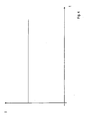
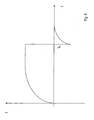
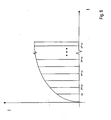
- FIGS. 3 to 5 show by way of example responses, ie curves of load currents I as a function of time t for different idealized electrical devices, whose properties are based on a jump in the voltage through corresponding characteristic curves for a substantially capacitive load, a constant ohmic resistance and an inductive load, such as a coil are given.
- the response signals at the analog inputs 46 1 to 46 n are substantially proportional to these characteristics.
- FIG. 3 shows the typical profile for a series connection of a resistor and a capacitor or a capacitor, wherein the characteristic curve is determined by the size of the resistor or the size of the capacitor.
- Fig. 4 shows the response of a load with an ohmic resistance, in which virtually immediately a stationary, the size of the resistor corresponding current value is achieved without a transient.
- FIG. 5 shows the response of an inductive load, for example a motor, when it is switched on and later switched off at the time t0.
- an inductive load for example a motor
- Another particular type of load is represented by light bulbs, where a very large current initially occurs because the filament has a relatively high conductivity when cold. However, the current then falls very quickly back to a lower value, since the filament heats up and thus receives a higher resistance. Thereafter, a constant current is achieved similar to an ohmic resistance. In this way, not only light bulbs can be detected on the basis of the course and the asymptotic value of the current, but also their parameters, for example the power consumption, can be determined.
- the reference data are stored in the form of a table in the first memory device 48 in connection with the corresponding types.
- the signal characteristics of the corresponding reference devices themselves are not used as reference data.
- reference values of parameters of predefined compensation functions are determined based on constant values of analog signals for the predetermined reference devices defining the types, which approximately reproduce the course of the analog signals for the reference device. For example, splines can be used as compensation functions. Only the corresponding coefficients are then determined and stored as reference data for the types.
- the comparison of the response signals detected for the loads 16 11 to 16 1n is now carried out in such a way that, starting from the response signal values recorded at constant time intervals, the predetermined compensation function is set by these values whose functional form corresponds to the functional form of the compensation function used in the determination of the reference data , Values of the parameters or coefficients of the compensation function are determined so that they reproduce the detected response signals as well as possible.
- the resulting set of parameter or coefficient values is compared with the corresponding reference values in the first memory device 48.
- an appropriate type for the load is determined.
- the types of loads 16 11 to 16 1n are stored in the order of the outputs 26 11 to 26 n1 in the second memory device 50 and therefore form a determined connection pattern in the sense of the present invention.
- the configuration device 52 is designed so that the connection pattern can be read out via the bus interface 28 and the bus 12 from the central control unit 10.
- a method for integrating a driver module in a motor vehicle electrical system proceeds as follows:
- the central control unit 10 now queries via the bus 12, the detected connection pattern.
- the central control unit 10 In the memory 20 of the central control unit 10 are all possible when using the central control unit 10 in motor vehicle electrical connection pattern of electrical loads or loads on driver modules in conjunction with driver parameters and identifiers stored for the signal channels to be used for the corresponding electrical devices.
- connection patterns are then compared with the stored predefined connection patterns.
- the corresponding driver module including the connected to this electrical equipment or loads is identified in its function and it will be sent to this the parameters to be used for the driver, such as maximum allowable currents or diagnostic parameters, and set there.
- predefined signal channels for electrical devices are assigned to the respective concrete electrical devices or loads, so that, for example, a signal channel corresponding to a turn signal on the left also actually leads to the switching of a turn signal lamp on a corresponding driver module.
- connection patterns are partially shown by way of example for the driver modules 14 1 and 14 m .
- an incandescent lamp 16 1n with, for example, 21 W power consumption and a plurality of ohmic loads 16 11 to 16 1n-1 occur as types of electrical devices.
- connection pattern starting with an ohmic resistor 16 m1 has, in addition to other devices, a motor 16 mn-1 as an inductive load and a light bulb 16 mn with in the example 21 watt power consumption as types of electrical devices.
- connection pattern includes the types in the order of the respective outputs of the driver modules, a unique assignment of loads of the same type with different functions is possible.
Landscapes
- Engineering & Computer Science (AREA)
- Computer Networks & Wireless Communication (AREA)
- Signal Processing (AREA)
- Control Of Electric Motors In General (AREA)
- Testing Electric Properties And Detecting Electric Faults (AREA)
Claims (10)
- Procédé pour implanter au moins un module formant étage d'attaque (141, ..., 14m) dans un système électrique d'un véhicule automobile, qui comprend au moins le au moins un module formant étage d'attaque (141, ..., 14m), des dispositifs électriques (1611, ..., 16mn) de types possibles prédéterminés, raccordés à des entrées et/ou à des sorties (2611, ..., 26mn) du module formant étage d'attaque (141, ..., 14m), ainsi qu'une unité de commande (10) reliée au au moins un module formant étage d'attaque (141, ..., 14m) par l'intermédiaire de canaux de transmission de signaux (3011, ..., 30mn), caractérisé en ce que
pour le fonctionnement des dispositifs électriques (1611, ..., 16mn), l'unité de commande (10) émet ou reçoit, par l'intermédiaire des canaux de transmission de signaux de signaux (3011, ..., 30mn) associés à ces dispositifs, des signaux en direction et/ou en provenance d'au moins un module formant étage d'attaque (141, ..., 14m),
dans lequel
un modèle de raccordement du au moins un module formant étage d'attaque (141, ..., 14m) est déterminé, modèle qui est défini au moins par les types des dispositifs électriques (1611, ..., 16mn) raccordés au au moins un module formant étage d'attaque (141, ..., 14m), et par leur nombre respectif,
le modèle de raccordement déterminé est comparé à des modèles de raccordement prédéterminés pour des modules formant étages d'attaque (141, ..., 14m) qui sont utilisés éventuellement dans le système électrique du véhicule automobile et auxquels sont raccordés des dispositifs électriques (1611, ..., 16mn), auxquels est associé respectivement au moins un paramètre pour faire fonctionner le au moins un module formant étage d'attaque (141, ..., 14m) et/ou desdits dispositifs électriques (1611, ..., 16mn) qui y sont raccordés, et sur la base de la comparaison, au moins un paramètre est affecté au au moins un module formant étage d'attaque (141, ..., 14m), et/ou des dispositifs électriques (1611, ..., 16mn) raccordés au au moins un module formant étage d'attaque (141, ..., 14m) sont associés entre eux. - Procédé selon la revendication 1, caractérisé en ce que le modèle de raccordement contient en outre des indications sur quel type déterminé de dispositif électrique (1611, ..., 16mn) est raccordé à quelle sortie et/ou entrée (2611, ..., 26mn) du au moins un module formant étage d'attaque (141, ..., 14m).
- Procédé selon la revendication 1, caractérisé en ce que sur la base des paramètres des canaux prédéterminés de transmission de signaux (3011, ..., 30mn) sont associés aux dispositifs électriques (1611, ..., 16mn) sur la base des paramètres qui sont associés au modèle de raccordement déterminé par la comparaison.
- Procédé selon l'une des revendications précédentes, caractérisé en ce que plusieurs modules formant étages d'attaque identiques (141, ..., 14m) reliés à l'unité de commande (10) peuvent être configurés pour faire fonctionner au moins quelques-uns des dispositifs électriques (1611, ..., 16mn) et sont configurés automatiquement d'une manière correspondant aux dispositifs électriques (1611, ..., 16mn) qui leur sont raccordés.
- Procédé selon l'une des revendications précédentes, caractérisé en ce
que pour la détermination du modèle de raccordement, on détermine les types des dispositifs électriques raccordés au au moins un module formant étage d'attaque (141, ..., 14m) par le fait que des signaux électriques prédéterminés de test sont appliqués aux entrées ou aux sorties (2611, ..., 26mn),
qu'on détecte des signaux de réponse, signaux qui reproduisent des réponses des dispositifs électriques (1611, ..., 16mn) dans les signaux de test respectifs, et que pour la détermination de types prédéterminés des dispositifs électriques raccordés (1611, ..., 16mn), des données déterminées à partir des signaux de réponse sont comparées à des données de référence prédéterminées correspondantes pour des types prédéterminés possibles de dispositifs électriques (1611, ..., 16mn), pour lesquels est prévu le au moins un module formant étage d'attaque (141, ..., 14m). - Procédé selon la revendication 5, caractérisé en ce qu'on utilise comme signal de réponse respectivement un signal de courant et/ou un signal de tension, qui reproduit le courant ou la tension appliqué au dispositif électrique respectif (1611, ..., 16mn).
- Procédé selon la revendication 6, caractérisé en ce
qu'au moins un étage d'attaque (241, ..., 24n) du au moins un module formant étage d'attaque (141, ..., 14m) comporte comme interrupteur de charge un composant MOSFET (32) avec mesure de courant, qui délivre un signal de courant correspondant au courant de charge, et
qu'on utilise comme signal de réponse un signal de tension produit par le signal de courant dans un élément de résistance (R). - Procédé selon l'une des revendications 5 à 7, caractérisé en ce
qu'une allure dans le temps d'au moins un signal de réponse est détectée après un instant initial prédéterminé par le signal de test respectif, et
que le type des dispositifs électriques respectifs (1611, ..., 16mn) est déterminé sur la base au moins de l'allure dans le temps. - Procédé selon l'une des revendications 5 à 8, caractérisé en ce qu'on utilise des signaux de saut comme signaux de test.
- Procédé selon la revendication 9, caractérisé en ce que les signaux de test sont produits par le branchement ou le débranchement d'un dispositif électrique correspondant (1611, ..., 16mn).
Priority Applications (2)
| Application Number | Priority Date | Filing Date | Title |
|---|---|---|---|
| EP03027509A EP1536595B1 (fr) | 2003-11-28 | 2003-11-28 | Procédé pour implanter un module de gestion dans l'électronique automobile |
| DE50305438T DE50305438D1 (de) | 2003-11-28 | 2003-11-28 | Verfahren zum Einbinden eines Treibermoduls in eine Kraftfahrzeugelektrik |
Applications Claiming Priority (1)
| Application Number | Priority Date | Filing Date | Title |
|---|---|---|---|
| EP03027509A EP1536595B1 (fr) | 2003-11-28 | 2003-11-28 | Procédé pour implanter un module de gestion dans l'électronique automobile |
Publications (2)
| Publication Number | Publication Date |
|---|---|
| EP1536595A1 EP1536595A1 (fr) | 2005-06-01 |
| EP1536595B1 true EP1536595B1 (fr) | 2006-10-18 |
Family
ID=34442915
Family Applications (1)
| Application Number | Title | Priority Date | Filing Date |
|---|---|---|---|
| EP03027509A Expired - Lifetime EP1536595B1 (fr) | 2003-11-28 | 2003-11-28 | Procédé pour implanter un module de gestion dans l'électronique automobile |
Country Status (2)
| Country | Link |
|---|---|
| EP (1) | EP1536595B1 (fr) |
| DE (1) | DE50305438D1 (fr) |
Cited By (1)
| Publication number | Priority date | Publication date | Assignee | Title |
|---|---|---|---|---|
| DE102023211673A1 (de) | 2023-11-23 | 2025-05-28 | Robert Bosch Gesellschaft mit beschränkter Haftung | Endstufen-Treiber-Einheit |
Families Citing this family (1)
| Publication number | Priority date | Publication date | Assignee | Title |
|---|---|---|---|---|
| DE102005060607A1 (de) * | 2005-12-17 | 2007-06-21 | Conti Temic Microelectronic Gmbh | Vorrichtung und Verfahren zur Erfassung und Verarbeitung von Messwerten |
Family Cites Families (3)
| Publication number | Priority date | Publication date | Assignee | Title |
|---|---|---|---|---|
| AU1260697A (en) * | 1996-02-21 | 1997-08-28 | Consolidated Technologies International | Multiplexed electrical system having a central controller and programmable control nodes |
| US6249060B1 (en) * | 1999-06-18 | 2001-06-19 | Jonathan P. Osha | Multiplexed cabling system for a vehicle |
| DE10203341A1 (de) * | 2002-01-29 | 2003-07-31 | Bayerische Motoren Werke Ag | Elektronisches Steuergerät für ein Kraftfahrzeug oder ein Fahrzeug-Antriebsaggregat |
-
2003
- 2003-11-28 DE DE50305438T patent/DE50305438D1/de not_active Expired - Fee Related
- 2003-11-28 EP EP03027509A patent/EP1536595B1/fr not_active Expired - Lifetime
Cited By (1)
| Publication number | Priority date | Publication date | Assignee | Title |
|---|---|---|---|---|
| DE102023211673A1 (de) | 2023-11-23 | 2025-05-28 | Robert Bosch Gesellschaft mit beschränkter Haftung | Endstufen-Treiber-Einheit |
Also Published As
| Publication number | Publication date |
|---|---|
| DE50305438D1 (de) | 2006-11-30 |
| EP1536595A1 (fr) | 2005-06-01 |
Similar Documents
| Publication | Publication Date | Title |
|---|---|---|
| DE19514738B4 (de) | Generator-Steuervorrichtung für Kraftfahrzeuge | |
| DE102010053304B4 (de) | Steuergerät mit einem zur Verarbeitung von Signalen unterschiedlicher Sensortypen eingerichteten Eingang und Verfahren zum Anpassen eines Steuergeräts | |
| DE10146556A1 (de) | Verfahren und Vorrichtung zum Erfassen des Zustandes eines Fahrzeuges | |
| WO2014086651A2 (fr) | Procédé pour une liaison commandée de plusieurs branches d'un réseau de bord d'un véhicule, unité de commande pour exécuter le procédé ainsi que réseau de bord | |
| DE102021207529A1 (de) | System und Verfahren zum Ansteuern einer multifunktionalen LED-Leuchte basierend auf einem Einzelkanal | |
| DE4338462B4 (de) | Kontrollsystem für elektrische Verbraucher in Kraftfahrzeugen | |
| DE112018004725T5 (de) | Stromfluss-Steuereinrichtung | |
| DE10357293B4 (de) | Lampensteuervorrichtung und Verfahren zum Betrieb einer Lampensteuervorrichtung | |
| EP1536595B1 (fr) | Procédé pour implanter un module de gestion dans l'électronique automobile | |
| DE102005025573A1 (de) | Multiplexing-System für Boote oder Wohnfahrzeuge | |
| DE10155847B4 (de) | Verfahren und Schaltungsanordnung zur Diagnose von Endstufen in Steuergeräten | |
| EP1536596B1 (fr) | Module de gestion et procédé pour configurer un module de gestion | |
| EP1362403B1 (fr) | Dispositif de detection d'erreur dans un reseau de bord multitension | |
| EP2086084A1 (fr) | Réseau de bord à DEL | |
| DE102006040404B4 (de) | Flexibles Verdrahtungssystem für ein elektronisches System | |
| DE102017116647A1 (de) | Kalibrierung der Versorgungsspannung für Beleuchtungssysteme | |
| DE102004013574A1 (de) | Drahtloser RF-Fernsteuerzonenverbinder und zugehöriges System | |
| EP3964033A1 (fr) | Procédé pour faire fonctionner un variateur | |
| EP3590770B1 (fr) | Dispositif de commande d'un consommateur électrique dans un réseau embarqué de véhicule et réseau embarqué d'un véhicule | |
| DE102007022341B3 (de) | Tastsensoreinheit | |
| DE102004013486A1 (de) | Fernsteuerzonenverbinder und zugehöriges System | |
| EP1216163B1 (fr) | Dispositif et procede de commande centrale de l'eclairage interieur d'un vehicule a moteur | |
| DE102006022615A1 (de) | Vorrichtung und Verfahren zum Betreiben eines elektrischen Stellglieds | |
| DE102016215568A1 (de) | Elektrisches Verbrauchsmodul für ein Kraftfahrzeug | |
| EP1529692B1 (fr) | Procédé et dispositif pour commander l'alimentation de tension dans un réseau de bord d'automobile |
Legal Events
| Date | Code | Title | Description |
|---|---|---|---|
| PUAI | Public reference made under article 153(3) epc to a published international application that has entered the european phase |
Free format text: ORIGINAL CODE: 0009012 |
|
| 17P | Request for examination filed |
Effective date: 20041025 |
|
| AK | Designated contracting states |
Kind code of ref document: A1 Designated state(s): AT BE BG CH CY CZ DE DK EE ES FI FR GB GR HU IE IT LI LU MC NL PT RO SE SI SK TR |
|
| AX | Request for extension of the european patent |
Extension state: AL LT LV MK |
|
| GRAP | Despatch of communication of intention to grant a patent |
Free format text: ORIGINAL CODE: EPIDOSNIGR1 |
|
| GRAS | Grant fee paid |
Free format text: ORIGINAL CODE: EPIDOSNIGR3 |
|
| AKX | Designation fees paid |
Designated state(s): DE FR GB IT SE |
|
| GRAA | (expected) grant |
Free format text: ORIGINAL CODE: 0009210 |
|
| AK | Designated contracting states |
Kind code of ref document: B1 Designated state(s): DE FR GB IT SE |
|
| PG25 | Lapsed in a contracting state [announced via postgrant information from national office to epo] |
Ref country code: IT Free format text: LAPSE BECAUSE OF FAILURE TO SUBMIT A TRANSLATION OF THE DESCRIPTION OR TO PAY THE FEE WITHIN THE PRESCRIBED TIME-LIMIT;WARNING: LAPSES OF ITALIAN PATENTS WITH EFFECTIVE DATE BEFORE 2007 MAY HAVE OCCURRED AT ANY TIME BEFORE 2007. THE CORRECT EFFECTIVE DATE MAY BE DIFFERENT FROM THE ONE RECORDED. Effective date: 20061018 |
|
| REG | Reference to a national code |
Ref country code: GB Ref legal event code: FG4D Free format text: NOT ENGLISH |
|
| GBT | Gb: translation of ep patent filed (gb section 77(6)(a)/1977) |
Effective date: 20061018 |
|
| REF | Corresponds to: |
Ref document number: 50305438 Country of ref document: DE Date of ref document: 20061130 Kind code of ref document: P |
|
| REG | Reference to a national code |
Ref country code: SE Ref legal event code: TRGR |
|
| ET | Fr: translation filed | ||
| PLBE | No opposition filed within time limit |
Free format text: ORIGINAL CODE: 0009261 |
|
| STAA | Information on the status of an ep patent application or granted ep patent |
Free format text: STATUS: NO OPPOSITION FILED WITHIN TIME LIMIT |
|
| 26N | No opposition filed |
Effective date: 20070719 |
|
| PGFP | Annual fee paid to national office [announced via postgrant information from national office to epo] |
Ref country code: DE Payment date: 20081120 Year of fee payment: 6 |
|
| PGFP | Annual fee paid to national office [announced via postgrant information from national office to epo] |
Ref country code: IT Payment date: 20081127 Year of fee payment: 6 |
|
| PGFP | Annual fee paid to national office [announced via postgrant information from national office to epo] |
Ref country code: FR Payment date: 20081112 Year of fee payment: 6 |
|
| PGFP | Annual fee paid to national office [announced via postgrant information from national office to epo] |
Ref country code: GB Payment date: 20081126 Year of fee payment: 6 |
|
| EUG | Se: european patent has lapsed | ||
| GBPC | Gb: european patent ceased through non-payment of renewal fee |
Effective date: 20091128 |
|
| REG | Reference to a national code |
Ref country code: FR Ref legal event code: ST Effective date: 20100730 |
|
| PG25 | Lapsed in a contracting state [announced via postgrant information from national office to epo] |
Ref country code: FR Free format text: LAPSE BECAUSE OF NON-PAYMENT OF DUE FEES Effective date: 20091130 |
|
| PG25 | Lapsed in a contracting state [announced via postgrant information from national office to epo] |
Ref country code: DE Free format text: LAPSE BECAUSE OF NON-PAYMENT OF DUE FEES Effective date: 20100601 |
|
| PG25 | Lapsed in a contracting state [announced via postgrant information from national office to epo] |
Ref country code: GB Free format text: LAPSE BECAUSE OF NON-PAYMENT OF DUE FEES Effective date: 20091128 |
|
| PG25 | Lapsed in a contracting state [announced via postgrant information from national office to epo] |
Ref country code: IT Free format text: LAPSE BECAUSE OF NON-PAYMENT OF DUE FEES Effective date: 20091128 |
|
| PG25 | Lapsed in a contracting state [announced via postgrant information from national office to epo] |
Ref country code: SE Free format text: LAPSE BECAUSE OF NON-PAYMENT OF DUE FEES Effective date: 20091129 |
|
| PGFP | Annual fee paid to national office [announced via postgrant information from national office to epo] |
Ref country code: SE Payment date: 20111125 Year of fee payment: 9 |