EP1537007B1 - Universelles transportfahrzeug mit variabler spurweite, radstand und bodenfreiheit - Google Patents
Universelles transportfahrzeug mit variabler spurweite, radstand und bodenfreiheit Download PDFInfo
- Publication number
- EP1537007B1 EP1537007B1 EP03758207A EP03758207A EP1537007B1 EP 1537007 B1 EP1537007 B1 EP 1537007B1 EP 03758207 A EP03758207 A EP 03758207A EP 03758207 A EP03758207 A EP 03758207A EP 1537007 B1 EP1537007 B1 EP 1537007B1
- Authority
- EP
- European Patent Office
- Prior art keywords
- chassis
- transport vehicle
- universal transport
- joined
- vehicle
- Prior art date
- Legal status (The legal status is an assumption and is not a legal conclusion. Google has not performed a legal analysis and makes no representation as to the accuracy of the status listed.)
- Expired - Lifetime
Links
- 230000004048 modification Effects 0.000 claims description 2
- 238000012986 modification Methods 0.000 claims description 2
- 239000000725 suspension Substances 0.000 abstract 3
- 230000004913 activation Effects 0.000 description 3
- 238000000926 separation method Methods 0.000 description 3
- 206010033892 Paraplegia Diseases 0.000 description 2
- 238000006073 displacement reaction Methods 0.000 description 1
- 230000001939 inductive effect Effects 0.000 description 1
- 238000012423 maintenance Methods 0.000 description 1
Images

Classifications
-
- B—PERFORMING OPERATIONS; TRANSPORTING
- B62—LAND VEHICLES FOR TRAVELLING OTHERWISE THAN ON RAILS
- B62D—MOTOR VEHICLES; TRAILERS
- B62D49/00—Tractors
- B62D49/06—Tractors adapted for multi-purpose use
- B62D49/0678—Tractors of variable track width or wheel base
-
- B—PERFORMING OPERATIONS; TRANSPORTING
- B62—LAND VEHICLES FOR TRAVELLING OTHERWISE THAN ON RAILS
- B62D—MOTOR VEHICLES; TRAILERS
- B62D21/00—Understructures, i.e. chassis frame on which a vehicle body may be mounted
- B62D21/14—Understructures, i.e. chassis frame on which a vehicle body may be mounted of adjustable length or width
-
- B—PERFORMING OPERATIONS; TRANSPORTING
- B60—VEHICLES IN GENERAL
- B60G—VEHICLE SUSPENSION ARRANGEMENTS
- B60G2300/00—Indexing codes relating to the type of vehicle
- B60G2300/40—Variable track or wheelbase vehicles
Definitions
- the invention relates to a universal transport vehicle, including the track, that is to say the width between the wheels of each of the two front and rear trains, the wheelbase, ie the distance between the front train and the train. rear, and the ground clearance, are variable.
- US 3,306,390 is considered to be the state of the art closest to the subject of claim 1 and discloses a universal transport vehicle comprising four independent wheels each mounted on a hub carried by a support arm secured to the chassis of the vehicle each carrier arm being hinged to the frame along a hinge axis.
- the object of the present invention is first of all to overcome these disadvantages; but on the other hand and above all to offer a versatile vehicle, whose lane modification, wheelbase and ground clearance can be achieved in a single maneuver, according to continuous values.
- the universal conveying vehicle according to the invention is defined by the features of claim 1.
- the member in question when the member in question is actuated, it acts on the carrying arms, causing either rotation in the direction of the chassis and the decrease in the width of the track and consequently the decrease in the wheelbase, that is to say contrary the rotation of the carrier arms opposite the chassis, and therefore the spacing of the track, and corollary the increase in the wheelbase.
- this activation member is constituted by a worm screw secured to the frame, on which two rings are able to move in translation in an opposing manner, at the level of which is secured respective end of tie rods secured to the carrying arms.
- the activation member is constituted by a jack secured to the frame, the other point of application is constituted by the carrier arm itself.
- the action is directly performed on the support arm.
- the axis of articulation of the carrier arms on the chassis is inclined relative to the vertical, so as to simultaneously induce with the spacing of the track and the increase in the wheelbase, an increase in the guard at ground.
- This inclination is commonly called hunting angle.
- said carrier arms of the same set of wheels are connected in pairs to the activation member. In this way, when said member is activated, it simultaneously and symmetrically induces the spacing of the wheels of the train considered.
- the vehicle comprises at least one set of directional wheels, secured to the chassis, in addition to the main support arm, also by a parallelism arm, integral with said chassis, said arm being articulated to said chassis by a vertical axis and being rotatable relative to this axis by means of a steering bar driven in translation by a rack / pinion assembly or any other equivalent means.
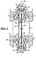
- Figures 1 and 2 are schematic representations of the operating principle of the vehicle according to the invention, illustrating in particular the variation of track and wheelbase, respectively narrow track and wide track.
- Figure 3 also schematically illustrates the variation of the ground clearance of said vehicle.
- This vehicle comprises a referenced chassis (C), incorporating two oscillating axles, of which only the front axle (1) has been shown.
- Four independent wheels (2), (3) (4) and (5) are mounted on said axles.
- Each of the front wheels (2) and (3) is steered and mounted on a hub, respectively (7) and (9), secured to the chassis via a carrier arm, respectively (6) and (8).
- These support arms (6, 8) are articulated on the frame (1) at hinge pins, also called pivot axes (10) and (11) inclined at a flush angle relative to the vertical, as can be seen in Figure 3. This inclination increases the ground clearance, especially during the track gauge phases.
- pivot axes are positioned in the vicinity of the front end of the frame.
- the hubs (7) and (9) of the two steering wheels (2) and (3) are furthermore secured to the front axle (1) and more precisely to a directional member (12) by means of an arm maintaining the parallelism (13) and (14).
- These holding arms are also articulated at the directional member (12) rotatably mounted relative to the frame, at hinge pins (15) and (16).
- these also comprise a hub (20) (21), secured to the rear axle by means of support arms (22) and (23) articulated at the axes - pivot (24) and (25) on said frame, also likely to have a flush angle relative to the vertical.
- the pivot axes are positioned adjacent the rear end of the frame.
- the hubs (20) and (21) are also secured at a directional member (26) by means of parallelism holding arms (27) (28) secured to a directional member (26) at the level of hinge pins (29) and (30), said directional member (26) being also rotatably mounted relative to the frame.
- the support arms (6) and (8) are connected by means of rods (31) and (32) to a ring (33) slidable on a worm (34) oriented along the main axis (35) of said vehicle, and secured to the chassis.
- the carrier arms (22) and (23) of the rear wheels (4) and (5) are secured simultaneously via links (36) and (37) to a ring (38), slidable on the same worm (34).
- the rings (33) and (38) are brought closer to one another, inducing traction on the said support arms (6). and (8), (22) and (23), causing the wheels to steering of the axis (35) of the vehicle, and thus the narrowing of the track of said front and rear wheels simultaneously, in addition to a decrease in the wheelbase.
- this decrease in track and wheelbase is accompanied by a decrease in the ground clearance of the chassis and therefore of the vehicle.
- this worm (34) can be performed electrically or by means of a pneumatic or hydraulic cylinder (not shown).
- the spacing or the approximation of the support arms can be achieved by means of cylinders, acting independently or integrally at each of the support arms.
- the directional members, respectively (12) and (26) are interconnected by means of a rigid rod (40), capable of to be moved in translation by means of a member (41) of the pinion type, acting on a rack integral or constitutive of said rigid rod (40).
- the pinion + rack assembly could again be replaced by a jack, integral with the frame, and whose point of application is fixed on said directional members
- the axes of maintenance of the parallelism (27) and (28) of the wheels are mounted in cantilever relative to the axis of the hub, this promotes the rotation of said rear wheels.
- the universal vehicle according to the invention therefore has many advantages over the devices of the prior art. In addition to the possible simplification and automation of its configuration, it also provides greater stability, which is very important both for applications to public works, transport or handling equipment, for paraplegic trolleys.
Landscapes
- Engineering & Computer Science (AREA)
- Chemical & Material Sciences (AREA)
- Combustion & Propulsion (AREA)
- Transportation (AREA)
- Mechanical Engineering (AREA)
- Steering-Linkage Mechanisms And Four-Wheel Steering (AREA)
- Body Structure For Vehicles (AREA)
- Platform Screen Doors And Railroad Systems (AREA)
- Vehicle Body Suspensions (AREA)
- Control Of Position, Course, Altitude, Or Attitude Of Moving Bodies (AREA)
- Steering Controls (AREA)
- Handcart (AREA)
- Road Paving Structures (AREA)
- Refuge Islands, Traffic Blockers, Or Guard Fence (AREA)
Claims (7)
- Universelles Transportfahrzeug mit vier unabhängigen Rädern (2-5), von denen jedes an einer Nabe (7, 9, 20, 21) angebracht ist, die durch einen fest mit dem Fahrgestell (C) des Fahrzeugs verbundenen Tragarm (6, 8, 22, 23) getragen wird, nämlich einem vorderen Radsatz und einem hinteren Radsatz, bei dem jeder der Tragarme (6, 8, 22, 23) entlang einer Gelenkachse oder Schwenkachse (10, 11, 24, 25) an dem Fahrgestell (C) angelenkt ist und die genannten Tragarme direkt oder indirekt mit einem oder mehreren Betätigungsmitteln (34) verbunden sind, welche gleichzeitig die Drehung der genannten Tragarme in bezug auf die genannten Gelenkachsen mindestens eines der Radsätze, nämlich des vorderen bzw. des hinteren, und die Veränderung des Radstandes des Fahrzeugs sicherstellen, dadurch gekennzeichnet, daß die genannten Gelenkachsen oder Schwenkachsen (10, 11, 24, 25) der genannten Tragarme (6, 8, 22, 23) vor dem vorderen Radsatz bzw. hinter dem hinteren Radsatz angeordnet sind, wenn sich das genannte universelle Fahrzeug in der Stellung mit minimaler Spurweite befindet.
- Universelles Transportfahrzeug nach Anspruch 1, dadurch gekennzeichnet, daß die Tragarme (6, 8, 22, 23) mit dem oder den Betätigungsmitteln (34) über Schwenkstangen (31, 32, 36, 37) verbunden sind.
- Universelles Transportfahrzeug nach Anspruch 2, dadurch gekennzeichnet, daß das oder die Betätigungsmittel (34) aus einer fest mit dem Fahrgestell (1) verbundenen Endlosschraube bestehen, an der sich in Translation ein Ring (33, 38) verschieben kann, an dessen Bereich das jeweilige Ende der genannten Schwenkstangen (31, 32, 36, 37) befestigt ist.
- Universelles Transportfahrzeug nach Anspruch 3, dadurch gekennzeichnet, daß es nur ein einziges Betätigungsmittel (34) aufweist, an dem sich in gegenwirkender Weise die Ringe (33, 38) verschieben können, wodurch sie eine gleichzeitige Variation der vorderen und hinteren Spurweite und der Länge des Radstandes herbeiführen.
- Universelles Transportfahrzeug nach Anspruch 1, dadurch gekennzeichnet, daß das Betätigungsmittel aus einem fest mit dem Fahrgestell verbundenen Zylinder besteht, dessen anderer Angriffspunkt von dem Tragarm selbst (6, 8, 22, 23) gebildet wird.
- Universelles Transportfahrzeug nach einem der Ansprüche 1 bis 5, dadurch gekennzeichnet, daß die Gelenkachse (10, 11, 24, 25) der Tragarme (6, 8, 22, 23) an dem Fahrgestell in bezug auf die Vertikale geneigt ist, so daß sie gleichzeitig mit der Verbreiterung der Spur und der Vergrößerung des Radstandes eine Vergrößerung der Bodenfreiheit herbeiführt.
- Universelles Transportfahrzeug nach einem der Ansprüche 1 bis 6, dadurch gekennzeichnet, daß es mindestens einen Satz gelenkter Räder aufweist, welche mit dem Fahrgestell außer durch den Haupt-Tragarm (6, 8, 22, 23) ebenfalls durch einen über ein Lenkmittel (12, 26) mit dem Fahrgestell (1) fest verbundenen Arm zum Erhalt der Parallelität (13, 14, 27, 28) fest verbunden sind, wobei die genannten Arme an den genannten Lenkmitteln (12, 26) durch eine vertikale Achse (15, 16, 29, 30) angelenkt sind und sich in bezug auf diese Achse mittels einer Lenkstange (40) drehen können, welche durch eine Anordnung aus Zahnstange und Zahnrad oder ein beliebiges anderes gleichwertiges Mittel in Translation versetzt werden kann.
Applications Claiming Priority (3)
| Application Number | Priority Date | Filing Date | Title |
|---|---|---|---|
| FR0211181A FR2844245B1 (fr) | 2002-09-10 | 2002-09-10 | Vehicule universel de transport a voie, empattement et garde au sol variables |
| FR0211181 | 2002-09-10 | ||
| PCT/FR2003/002460 WO2004024541A1 (fr) | 2002-09-10 | 2003-08-05 | Vehicule universel de transport a voie, empattement et garde au sol variables |
Publications (2)
| Publication Number | Publication Date |
|---|---|
| EP1537007A1 EP1537007A1 (de) | 2005-06-08 |
| EP1537007B1 true EP1537007B1 (de) | 2006-04-26 |
Family
ID=31725963
Family Applications (1)
| Application Number | Title | Priority Date | Filing Date |
|---|---|---|---|
| EP03758207A Expired - Lifetime EP1537007B1 (de) | 2002-09-10 | 2003-08-05 | Universelles transportfahrzeug mit variabler spurweite, radstand und bodenfreiheit |
Country Status (6)
| Country | Link |
|---|---|
| EP (1) | EP1537007B1 (de) |
| AT (1) | ATE324310T1 (de) |
| AU (1) | AU2003274224A1 (de) |
| DE (1) | DE60304873T2 (de) |
| FR (1) | FR2844245B1 (de) |
| WO (1) | WO2004024541A1 (de) |
Cited By (4)
| Publication number | Priority date | Publication date | Assignee | Title |
|---|---|---|---|---|
| US7832741B2 (en) | 2004-03-24 | 2010-11-16 | Genie Industries, Inc. | Vehicle support system |
| CN106082046A (zh) * | 2016-08-05 | 2016-11-09 | 湖南星邦重工有限公司 | 一种高空作业平台的底盘及高空作业平台 |
| EP4257460A1 (de) * | 2022-04-05 | 2023-10-11 | Roberto Romboli | Vorrichtung zum verändern des spurmasses und des schwerpunktes von kettenfahrzeugen |
| EP4197706A4 (de) * | 2020-12-03 | 2024-03-27 | Samsung Electronics Co., Ltd. | Fahrzeug für unebenes gelände |
Families Citing this family (31)
| Publication number | Priority date | Publication date | Assignee | Title |
|---|---|---|---|---|
| WO2005056308A1 (en) * | 2003-12-11 | 2005-06-23 | Singapore Technologies Kinetics Ltd | Wheel track adjustment system |
| NZ539543A (en) | 2005-04-20 | 2008-02-29 | Graham John Mahy | Vehicle with adjustable track width and wheelbase |
| WO2008020861A1 (en) * | 2006-08-18 | 2008-02-21 | Oshkosh Truck Corporation | Modular metamorphic vehicle |
| WO2007097779A2 (en) | 2005-08-19 | 2007-08-30 | Oshkosh Truck Corporation | Modular metamorphic vehicle |
| GB2433236B (en) * | 2005-12-16 | 2007-11-07 | Lotus Car | A motorcycle having a vehicle wheelbase variation mechanism |
| HUP0700422A2 (en) * | 2007-06-19 | 2011-02-28 | Zsolt Beck | Vehicle with more than three wheels with changeable track |
| DE102007053906A1 (de) * | 2007-11-09 | 2009-05-14 | Herbert Dammann Gmbh | Fahrgestell für Spezialfahrzeuge |
| GB0815314D0 (en) * | 2008-08-22 | 2008-09-24 | Chem Europ Bv Ag | Agricultural application machine with variable width track |
| ES2393907T3 (es) * | 2010-05-17 | 2012-12-28 | Jaxa Networks | Vehículo que tiene ancho de vía variable |
| WO2013051298A1 (ja) * | 2011-05-16 | 2013-04-11 | 日本精工株式会社 | 車両用懸架装置 |
| CN103057631B (zh) * | 2013-02-08 | 2015-04-01 | 吉林大学 | 一种行走机械的变轮距悬架机构 |
| DE102013004951B4 (de) | 2013-03-22 | 2020-02-13 | Audi Ag | Radaufhängung für ein Fahrzeug |
| CA3107876C (en) | 2013-05-23 | 2022-11-29 | Q-Bot Limited | Method of covering a surface of a building and robot therefor |
| CN103448797B (zh) * | 2013-09-03 | 2015-12-09 | 中国农业大学 | 轮距调整转向联动机构 |
| CN103448795B (zh) * | 2013-09-03 | 2015-12-23 | 中国农业大学 | 适应轮距调整底盘的转向机构 |
| GB201405527D0 (en) * | 2014-03-27 | 2014-05-14 | Mill Facility The Ltd | A driveable vehicle unit |
| CN104149851B (zh) * | 2014-08-22 | 2016-07-06 | 青岛理工大学 | 一种变轮距车辆的转向系统 |
| EP3568308B1 (de) | 2017-01-13 | 2021-01-20 | Triggo S.A. | Fahrzeugaufhängungssystem |
| WO2018150108A1 (fr) | 2017-02-20 | 2018-08-23 | Franck Guigan | Véhicule à géométrie variable |
| EP3392068A1 (de) * | 2017-04-18 | 2018-10-24 | AeroMobil R&D, s. r. o. | Aufhängungssystem |
| CN110103641B (zh) * | 2019-05-19 | 2020-02-07 | 柳州市孚桂智能科技有限公司 | 机动车轮距调节机构及其控制方法 |
| CN110143127B (zh) * | 2019-05-29 | 2023-05-30 | 张大朋 | 电动汽车、控制方法、计算机设备和存储介质 |
| US12194859B2 (en) | 2019-05-29 | 2025-01-14 | Ta-Peng Chang | Electric vehicle, automatic driving method and device, automatic freighting method and system |
| CN113022248A (zh) * | 2019-12-24 | 2021-06-25 | 沈阳新松机器人自动化股份有限公司 | 一种轮距可调机器人底盘 |
| US11608126B2 (en) * | 2020-01-16 | 2023-03-21 | Xtreme Manufacturing, Llc | Expendable wheel base chassis |
| EP4019301A1 (de) * | 2020-12-28 | 2022-06-29 | MARMIX GmbH & Co. KG | Spurweitenveränderliche achsvorrichtung, spezialfahrzeug und verwendung desselben |
| CN113184053B (zh) * | 2021-05-25 | 2022-07-01 | 吉林大学 | 一种横纵向间距可调式线控底盘及其控制方法 |
| US12103588B2 (en) * | 2022-01-21 | 2024-10-01 | Kabushiki Kaisha F.C.C. | Vehicle platform |
| WO2023180687A1 (en) * | 2022-03-23 | 2023-09-28 | Bae Systems Plc | Suspension system |
| CN115649290A (zh) * | 2022-11-14 | 2023-01-31 | 中国第一汽车股份有限公司 | 一种滑板底盘的轮距、轴距调整装置 |
| CN117284033B (zh) * | 2023-10-13 | 2024-07-09 | 科大天工智能装备技术(天津)有限公司 | 一种能够应用于整体式后桥的浮动悬架 |
Family Cites Families (6)
| Publication number | Priority date | Publication date | Assignee | Title |
|---|---|---|---|---|
| GB1050526A (de) * | 1962-07-02 | |||
| US3899037A (en) * | 1973-07-16 | 1975-08-12 | Paul A Yuker | Chassis apparatus for all terrain vehicles |
| JPS5288920A (en) * | 1976-01-17 | 1977-07-26 | Kubota Ltd | Apparatus for tread adjustment for tractor or the like |
| US4834409A (en) * | 1987-10-13 | 1989-05-30 | Kramer Duwayne E | Personal mobility vehicle with expansible wheel base and wheel track |
| BE1009973A4 (nl) * | 1996-01-03 | 1997-11-04 | Verstraete Eric | Terreinvoertuig om over waterlopen en oneffen terrein grond- en onderhoudswerken uit te voeren. |
| US6311795B1 (en) * | 2000-05-02 | 2001-11-06 | Case Corporation | Work vehicle steering and suspension system |
-
2002
- 2002-09-10 FR FR0211181A patent/FR2844245B1/fr not_active Expired - Fee Related
-
2003
- 2003-08-05 AT AT03758207T patent/ATE324310T1/de not_active IP Right Cessation
- 2003-08-05 WO PCT/FR2003/002460 patent/WO2004024541A1/fr not_active Ceased
- 2003-08-05 AU AU2003274224A patent/AU2003274224A1/en not_active Abandoned
- 2003-08-05 DE DE60304873T patent/DE60304873T2/de not_active Expired - Lifetime
- 2003-08-05 EP EP03758207A patent/EP1537007B1/de not_active Expired - Lifetime
Cited By (4)
| Publication number | Priority date | Publication date | Assignee | Title |
|---|---|---|---|---|
| US7832741B2 (en) | 2004-03-24 | 2010-11-16 | Genie Industries, Inc. | Vehicle support system |
| CN106082046A (zh) * | 2016-08-05 | 2016-11-09 | 湖南星邦重工有限公司 | 一种高空作业平台的底盘及高空作业平台 |
| EP4197706A4 (de) * | 2020-12-03 | 2024-03-27 | Samsung Electronics Co., Ltd. | Fahrzeug für unebenes gelände |
| EP4257460A1 (de) * | 2022-04-05 | 2023-10-11 | Roberto Romboli | Vorrichtung zum verändern des spurmasses und des schwerpunktes von kettenfahrzeugen |
Also Published As
| Publication number | Publication date |
|---|---|
| DE60304873T2 (de) | 2006-09-21 |
| AU2003274224A1 (en) | 2004-04-30 |
| ATE324310T1 (de) | 2006-05-15 |
| FR2844245B1 (fr) | 2005-04-29 |
| WO2004024541A1 (fr) | 2004-03-25 |
| EP1537007A1 (de) | 2005-06-08 |
| DE60304873D1 (de) | 2006-06-01 |
| FR2844245A1 (fr) | 2004-03-12 |
Similar Documents
| Publication | Publication Date | Title |
|---|---|---|
| EP1537007B1 (de) | Universelles transportfahrzeug mit variabler spurweite, radstand und bodenfreiheit | |
| EP3046780B1 (de) | Anordnung mit einem fahrgestell für ein fahrzeug mit variabler spur, z. b. ein landwirtschaftliches fahrzeug wie einen sprüher oder ein hohes reinigungsfahrzeug | |
| EP0215714B1 (de) | Rollstuhl für Körperbehinderte, insbesondere für ein Kind | |
| FR2489216A1 (fr) | Essieu de direction extensible pour appareil de levage mobile, notamment pour vehicule-grue et vehicule a plateforme elevatrice | |
| FR2619070A1 (fr) | Dispositif tendeur pour l'element souple ou articule d'un systeme de transmission ou de roulement | |
| WO1995009788A1 (fr) | Appareil de pose de vitrine de magasin | |
| CA1322150C (fr) | Dispositif de positionnement et de fixation d'un dispositif de chaine a neige auxiliaire pour vehicule routier | |
| FR2473444A1 (fr) | Vehicule sans conducteur a came de commande de vitesse de convoyeur utilisant ce vehicule | |
| EP1529722B1 (de) | Spurstellvorrichtung für Räder einer selben Achse | |
| FR2678888A1 (fr) | Tracteur enjambeur a voie reglable. | |
| FR3071472B1 (fr) | Vehicule agricole avec correction de glissement par les roues arriere | |
| FR3031069A1 (fr) | Vehicule equipe de systemes de correction de devers et de commande de direction pour ensemble roue, et un tel systeme | |
| FR2712137A3 (fr) | Faucheuse tractée. | |
| FR2772228A1 (fr) | Ramasseur repliable pour ensileuse | |
| CH407770A (fr) | Mécanisme pour solidariser en rotation les roues motrices d'un véhicule à moteur | |
| FR2903068A1 (fr) | Chariot comprenant des moyens de limitation de la rotation des roues | |
| FR2859440A1 (fr) | Essieu directeur a recuperation de trajectoire | |
| FR2647297A1 (fr) | Instrument aratoire comprenant un outil compose d'un element central en avant de deux elements lateraux pivotants | |
| FR2551015A1 (fr) | Vehicule a train avant et chassis deportables lateralement relativement | |
| FR2876974A1 (fr) | Remorque et dispositif pour la commande automatique de moyens de blocage equipant les roues d'un essieu d'une remorque | |
| FR2627931A1 (fr) | Charrue a largeur de travail variable | |
| FR2882622A1 (fr) | Andaineuse a bras porte-rotors telescopiques | |
| FR2702440A1 (fr) | Dispositif de réglage de la chasse d'un véhicule, notamment d'un kart. | |
| FR2512411A1 (fr) | Remorque | |
| EP0089910A1 (de) | Selbstfahrendes Geländefahrzeug mit veränderlichem geometrischen Rahmen |
Legal Events
| Date | Code | Title | Description |
|---|---|---|---|
| PUAI | Public reference made under article 153(3) epc to a published international application that has entered the european phase |
Free format text: ORIGINAL CODE: 0009012 |
|
| 17P | Request for examination filed |
Effective date: 20050201 |
|
| AK | Designated contracting states |
Kind code of ref document: A1 Designated state(s): AT BE BG CH CY CZ DE DK EE ES FI FR GB GR HU IE IT LI LU MC NL PT RO SE SI SK TR |
|
| AX | Request for extension of the european patent |
Extension state: AL LT LV MK |
|
| GRAP | Despatch of communication of intention to grant a patent |
Free format text: ORIGINAL CODE: EPIDOSNIGR1 |
|
| DAX | Request for extension of the european patent (deleted) | ||
| GRAS | Grant fee paid |
Free format text: ORIGINAL CODE: EPIDOSNIGR3 |
|
| GRAA | (expected) grant |
Free format text: ORIGINAL CODE: 0009210 |
|
| AK | Designated contracting states |
Kind code of ref document: B1 Designated state(s): AT BE BG CH CY CZ DE DK EE ES FI FR GB GR HU IE IT LI LU MC NL PT RO SE SI SK TR |
|
| PG25 | Lapsed in a contracting state [announced via postgrant information from national office to epo] |
Ref country code: IT Free format text: LAPSE BECAUSE OF FAILURE TO SUBMIT A TRANSLATION OF THE DESCRIPTION OR TO PAY THE FEE WITHIN THE PRESCRIBED TIME-LIMIT;WARNING: LAPSES OF ITALIAN PATENTS WITH EFFECTIVE DATE BEFORE 2007 MAY HAVE OCCURRED AT ANY TIME BEFORE 2007. THE CORRECT EFFECTIVE DATE MAY BE DIFFERENT FROM THE ONE RECORDED. Effective date: 20060426 Ref country code: SI Free format text: LAPSE BECAUSE OF FAILURE TO SUBMIT A TRANSLATION OF THE DESCRIPTION OR TO PAY THE FEE WITHIN THE PRESCRIBED TIME-LIMIT Effective date: 20060426 Ref country code: IE Free format text: LAPSE BECAUSE OF FAILURE TO SUBMIT A TRANSLATION OF THE DESCRIPTION OR TO PAY THE FEE WITHIN THE PRESCRIBED TIME-LIMIT Effective date: 20060426 Ref country code: FI Free format text: LAPSE BECAUSE OF FAILURE TO SUBMIT A TRANSLATION OF THE DESCRIPTION OR TO PAY THE FEE WITHIN THE PRESCRIBED TIME-LIMIT Effective date: 20060426 Ref country code: AT Free format text: LAPSE BECAUSE OF FAILURE TO SUBMIT A TRANSLATION OF THE DESCRIPTION OR TO PAY THE FEE WITHIN THE PRESCRIBED TIME-LIMIT Effective date: 20060426 Ref country code: CZ Free format text: LAPSE BECAUSE OF FAILURE TO SUBMIT A TRANSLATION OF THE DESCRIPTION OR TO PAY THE FEE WITHIN THE PRESCRIBED TIME-LIMIT Effective date: 20060426 Ref country code: SK Free format text: LAPSE BECAUSE OF FAILURE TO SUBMIT A TRANSLATION OF THE DESCRIPTION OR TO PAY THE FEE WITHIN THE PRESCRIBED TIME-LIMIT Effective date: 20060426 Ref country code: RO Free format text: LAPSE BECAUSE OF FAILURE TO SUBMIT A TRANSLATION OF THE DESCRIPTION OR TO PAY THE FEE WITHIN THE PRESCRIBED TIME-LIMIT Effective date: 20060426 Ref country code: NL Free format text: LAPSE BECAUSE OF FAILURE TO SUBMIT A TRANSLATION OF THE DESCRIPTION OR TO PAY THE FEE WITHIN THE PRESCRIBED TIME-LIMIT Effective date: 20060426 |
|
| REG | Reference to a national code |
Ref country code: GB Ref legal event code: FG4D Free format text: NOT ENGLISH |
|
| GBT | Gb: translation of ep patent filed (gb section 77(6)(a)/1977) |
Effective date: 20060426 |
|
| REG | Reference to a national code |
Ref country code: IE Ref legal event code: FG4D Free format text: LANGUAGE OF EP DOCUMENT: FRENCH |
|
| REF | Corresponds to: |
Ref document number: 60304873 Country of ref document: DE Date of ref document: 20060601 Kind code of ref document: P |
|
| PG25 | Lapsed in a contracting state [announced via postgrant information from national office to epo] |
Ref country code: DK Free format text: LAPSE BECAUSE OF FAILURE TO SUBMIT A TRANSLATION OF THE DESCRIPTION OR TO PAY THE FEE WITHIN THE PRESCRIBED TIME-LIMIT Effective date: 20060726 Ref country code: SE Free format text: LAPSE BECAUSE OF FAILURE TO SUBMIT A TRANSLATION OF THE DESCRIPTION OR TO PAY THE FEE WITHIN THE PRESCRIBED TIME-LIMIT Effective date: 20060726 |
|
| PG25 | Lapsed in a contracting state [announced via postgrant information from national office to epo] |
Ref country code: ES Free format text: LAPSE BECAUSE OF FAILURE TO SUBMIT A TRANSLATION OF THE DESCRIPTION OR TO PAY THE FEE WITHIN THE PRESCRIBED TIME-LIMIT Effective date: 20060806 |
|
| PG25 | Lapsed in a contracting state [announced via postgrant information from national office to epo] |
Ref country code: BE Free format text: LAPSE BECAUSE OF NON-PAYMENT OF DUE FEES Effective date: 20060831 Ref country code: MC Free format text: LAPSE BECAUSE OF NON-PAYMENT OF DUE FEES Effective date: 20060831 |
|
| PG25 | Lapsed in a contracting state [announced via postgrant information from national office to epo] |
Ref country code: PT Free format text: LAPSE BECAUSE OF FAILURE TO SUBMIT A TRANSLATION OF THE DESCRIPTION OR TO PAY THE FEE WITHIN THE PRESCRIBED TIME-LIMIT Effective date: 20060926 |
|
| REG | Reference to a national code |
Ref country code: FR Ref legal event code: TP |
|
| NLV1 | Nl: lapsed or annulled due to failure to fulfill the requirements of art. 29p and 29m of the patents act | ||
| REG | Reference to a national code |
Ref country code: IE Ref legal event code: FD4D |
|
| PLBE | No opposition filed within time limit |
Free format text: ORIGINAL CODE: 0009261 |
|
| STAA | Information on the status of an ep patent application or granted ep patent |
Free format text: STATUS: NO OPPOSITION FILED WITHIN TIME LIMIT |
|
| 26N | No opposition filed |
Effective date: 20070129 |
|
| BERE | Be: lapsed |
Owner name: OBRY, JEAN-MARIE Effective date: 20060831 |
|
| REG | Reference to a national code |
Ref country code: CH Ref legal event code: PL |
|
| GBPC | Gb: european patent ceased through non-payment of renewal fee |
Effective date: 20070805 |
|
| PG25 | Lapsed in a contracting state [announced via postgrant information from national office to epo] |
Ref country code: LI Free format text: LAPSE BECAUSE OF NON-PAYMENT OF DUE FEES Effective date: 20070831 Ref country code: GR Free format text: LAPSE BECAUSE OF FAILURE TO SUBMIT A TRANSLATION OF THE DESCRIPTION OR TO PAY THE FEE WITHIN THE PRESCRIBED TIME-LIMIT Effective date: 20060727 Ref country code: CH Free format text: LAPSE BECAUSE OF NON-PAYMENT OF DUE FEES Effective date: 20070831 |
|
| PG25 | Lapsed in a contracting state [announced via postgrant information from national office to epo] |
Ref country code: EE Free format text: LAPSE BECAUSE OF FAILURE TO SUBMIT A TRANSLATION OF THE DESCRIPTION OR TO PAY THE FEE WITHIN THE PRESCRIBED TIME-LIMIT Effective date: 20060426 Ref country code: BG Free format text: LAPSE BECAUSE OF FAILURE TO SUBMIT A TRANSLATION OF THE DESCRIPTION OR TO PAY THE FEE WITHIN THE PRESCRIBED TIME-LIMIT Effective date: 20060726 |
|
| PG25 | Lapsed in a contracting state [announced via postgrant information from national office to epo] |
Ref country code: HU Free format text: LAPSE BECAUSE OF FAILURE TO SUBMIT A TRANSLATION OF THE DESCRIPTION OR TO PAY THE FEE WITHIN THE PRESCRIBED TIME-LIMIT Effective date: 20061027 Ref country code: TR Free format text: LAPSE BECAUSE OF FAILURE TO SUBMIT A TRANSLATION OF THE DESCRIPTION OR TO PAY THE FEE WITHIN THE PRESCRIBED TIME-LIMIT Effective date: 20060426 Ref country code: LU Free format text: LAPSE BECAUSE OF NON-PAYMENT OF DUE FEES Effective date: 20060805 |
|
| PG25 | Lapsed in a contracting state [announced via postgrant information from national office to epo] |
Ref country code: GB Free format text: LAPSE BECAUSE OF NON-PAYMENT OF DUE FEES Effective date: 20070805 Ref country code: CY Free format text: LAPSE BECAUSE OF FAILURE TO SUBMIT A TRANSLATION OF THE DESCRIPTION OR TO PAY THE FEE WITHIN THE PRESCRIBED TIME-LIMIT Effective date: 20060426 |
|
| REG | Reference to a national code |
Ref country code: FR Ref legal event code: PLFP Year of fee payment: 14 |
|
| REG | Reference to a national code |
Ref country code: FR Ref legal event code: PLFP Year of fee payment: 15 |
|
| REG | Reference to a national code |
Ref country code: FR Ref legal event code: PLFP Year of fee payment: 16 |
|
| PGFP | Annual fee paid to national office [announced via postgrant information from national office to epo] |
Ref country code: IE Payment date: 20180809 Year of fee payment: 16 |
|
| PGFP | Annual fee paid to national office [announced via postgrant information from national office to epo] |
Ref country code: FR Payment date: 20190829 Year of fee payment: 17 |
|
| REG | Reference to a national code |
Ref country code: DE Ref legal event code: R119 Ref document number: 60304873 Country of ref document: DE |
|
| PG25 | Lapsed in a contracting state [announced via postgrant information from national office to epo] |
Ref country code: DE Free format text: LAPSE BECAUSE OF NON-PAYMENT OF DUE FEES Effective date: 20200303 |
|
| PG25 | Lapsed in a contracting state [announced via postgrant information from national office to epo] |
Ref country code: FR Free format text: LAPSE BECAUSE OF NON-PAYMENT OF DUE FEES Effective date: 20200831 |