EP1537014B1 - Poignee de bicyclette - Google Patents
Poignee de bicyclette Download PDFInfo
- Publication number
- EP1537014B1 EP1537014B1 EP04764244A EP04764244A EP1537014B1 EP 1537014 B1 EP1537014 B1 EP 1537014B1 EP 04764244 A EP04764244 A EP 04764244A EP 04764244 A EP04764244 A EP 04764244A EP 1537014 B1 EP1537014 B1 EP 1537014B1
- Authority
- EP
- European Patent Office
- Prior art keywords
- grip
- sleeve
- holding
- bicycle
- clamping means
- Prior art date
- Legal status (The legal status is an assumption and is not a legal conclusion. Google has not performed a legal analysis and makes no representation as to the accuracy of the status listed.)
- Expired - Lifetime
Links
Images



Classifications
-
- B—PERFORMING OPERATIONS; TRANSPORTING
- B62—LAND VEHICLES FOR TRAVELLING OTHERWISE THAN ON RAILS
- B62K—CYCLES; CYCLE FRAMES; CYCLE STEERING DEVICES; RIDER-OPERATED TERMINAL CONTROLS SPECIALLY ADAPTED FOR CYCLES; CYCLE AXLE SUSPENSIONS; CYCLE SIDECARS, FORECARS, OR THE LIKE
- B62K21/00—Steering devices
- B62K21/12—Handlebars; Handlebar stems
- B62K21/125—Extensions; Auxiliary handlebars
-
- B—PERFORMING OPERATIONS; TRANSPORTING
- B62—LAND VEHICLES FOR TRAVELLING OTHERWISE THAN ON RAILS
- B62K—CYCLES; CYCLE FRAMES; CYCLE STEERING DEVICES; RIDER-OPERATED TERMINAL CONTROLS SPECIALLY ADAPTED FOR CYCLES; CYCLE AXLE SUSPENSIONS; CYCLE SIDECARS, FORECARS, OR THE LIKE
- B62K21/00—Steering devices
- B62K21/26—Handlebar grips
-
- Y—GENERAL TAGGING OF NEW TECHNOLOGICAL DEVELOPMENTS; GENERAL TAGGING OF CROSS-SECTIONAL TECHNOLOGIES SPANNING OVER SEVERAL SECTIONS OF THE IPC; TECHNICAL SUBJECTS COVERED BY FORMER USPC CROSS-REFERENCE ART COLLECTIONS [XRACs] AND DIGESTS
- Y10—TECHNICAL SUBJECTS COVERED BY FORMER USPC
- Y10T—TECHNICAL SUBJECTS COVERED BY FORMER US CLASSIFICATION
- Y10T74/00—Machine element or mechanism
- Y10T74/20—Control lever and linkage systems
- Y10T74/20576—Elements
- Y10T74/20732—Handles
- Y10T74/2078—Handle bars
-
- Y—GENERAL TAGGING OF NEW TECHNOLOGICAL DEVELOPMENTS; GENERAL TAGGING OF CROSS-SECTIONAL TECHNOLOGIES SPANNING OVER SEVERAL SECTIONS OF THE IPC; TECHNICAL SUBJECTS COVERED BY FORMER USPC CROSS-REFERENCE ART COLLECTIONS [XRACs] AND DIGESTS
- Y10—TECHNICAL SUBJECTS COVERED BY FORMER USPC
- Y10T—TECHNICAL SUBJECTS COVERED BY FORMER US CLASSIFICATION
- Y10T74/00—Machine element or mechanism
- Y10T74/20—Control lever and linkage systems
- Y10T74/20576—Elements
- Y10T74/20732—Handles
- Y10T74/2078—Handle bars
- Y10T74/20828—Handholds and grips
Definitions
- the invention relates to a bicycle handle, especially for road bikes, mountain bikes and the like.
- Bicycle handles are designed essentially as cylindrical gripping elements in order to attach them to a bicycle handlebar can. To avoid slippage of the bicycle handle, it is arranged so that it protrudes from the gripping area of the bicycle handle. In this protruding clamping area of the bicycle handle is clamped by means of a screw connection with the bicycle handlebar.
- a bicycle handle holding horns which are configured substantially horn-shaped.
- the holding horns are inserted into a bicycle handlebar or plugged in from outside and jammed with this.
- the object of the invention is to provide a bicycle handle in which the support of a cyclist is improved.
- the bicycle handle according to the invention has a sleeve for attachment to a bicycle handlebar.
- the sleeve has a sleeve slot, so that the sleeve can be clamped to the bicycle handlebar.
- the bicycle handle also has a gripping element that can be at least partially gripped by a hand of a cyclist.
- the gripping element is arranged on an outer side of the sleeve and connected thereto.
- the gripping element extends over a part of the sleeve length, so that at one edge of the sleeve a clamping area remains free, in which a clamping means for clamping the bicycle handle with the bicycle handlebar is connected to the sleeve.
- the gripping element has a support part for supporting a palm and a holding part.
- the support member is configured, for example, substantially ridge-shaped, wedge-shaped and / or wing-shaped, so that forms a support surface on which the palm of a cyclist rests when the gripping element is gripped.
- the holding part protrudes from the sleeve into the clamping area and forms an integral unit, in particular with the supporting part.
- the support part and the holding part are designed such that together with the clamping means they form a common gripping surface and / or a common holding surface.
- the clamping means When the hand of the cyclist is in a gripping position, ie the gripping element is gripped substantially in the circumferential direction, the clamping means is engaged, so that the support part and the holding part with the clamping means form a common gripping surface.
- the gripping element When the cyclist's hand is in a stop position, ie, the gripping element is held substantially perpendicular to the bicycle handlebar at its outer end, the clamping means is kept, so that the support member and the holding part with the clamping means form a common holding surface.
- the clamping means is not arranged next to the gripping element, but in the gripping element.
- the applied clamping force of the clamping means is moved from outside to inside.
- the applied clamping force is thus closer to the point at which the greatest force is applied to the bicycle handle by the hand.
- comparable clamping force of the bicycle handle is better secured against unintentional twisting around the handlebars. Due to the improved anti-rotation protection, the bicycle rider's grip is maintained even under heavy loads, such as go downhill, improved.
- the width of the clamping means which is, for example, a slotted clamping ring, since a clamping area protruding from the actual gripping area of the bicycle handle is avoided. This is particularly advantageous in bent arms, since in such links the space available for a bicycle handle space is severely limited. This leaves more room for attaching further functional elements, e.g. a bicycle bell or a gear lever.
- the support member, the holding part and the clamping means are matched in shape in particular such that their surfaces are aligned, ie there are no disturbing projections, steps, paragraphs, trenches and the like. on. Instead, the support member and the holding member together with the clamping means form a common functional unit.
- the clamping means is not visually disturbing accessory, but part of the bicycle handle, so that optics and function are summarized in an integral design.
- the support member is both when gripping in the gripping surface as well as holding in the holding surface with the palm of the cyclist in contact.
- the support member thus forms, if necessary, together with the holding part of a support surface on which when grasping, i.
- the support member in particular a contact surface, which is preferably formed in such a three-dimensional that a substantially obstacle-free gripping is ensured when the palm rotates on the contact surface.
- the clamping means is designed as a holding horn.
- the holding surface is increased.
- the clamping means is in this embodiment, a part of the holding horn. Further, the grip of the cyclist when the hand is in the stop position is improved. Since the holding part is held in the holding, the holding horn can be made shorter and has a length which corresponds to the holding part substantially a hand width.
- An independent of the invention consists in a bicycle handle, which initially has a sleeve for attachment to a bicycle handlebar.
- the sleeve has a sleeve slot, so that the sleeve can be clamped to the bicycle handlebar.
- the bicycle handle also has a gripping element that can be at least partially gripped by a hand of a cyclist.
- the gripping element is arranged on an outer side of the sleeve and connected thereto. The gripping element extends over a part of the sleeve length, so that at one edge of the sleeve, a clamping area remains free for the arrangement of a clamping means.
- the bicycle handle also has a retaining horn with a clamping means, wherein the clamping means is arranged for connecting the retaining horn with the gripping element in the clamping region of the sleeve.
- the gripping element has a supporting part for supporting a palm.
- the support member is configured, for example, substantially ridge-shaped, wedge-shaped and / or wing-shaped, so that there is a support surface training on which the palm of a cyclist rests when the gripping element is gripped.
- the support member of the cyclist receives a support surface which is spaced from a central axis of the bicycle handlebar.
- the support member has for this purpose in particular a contact surface, which is preferably formed in such a three-dimensional manner that a substantially obstacle-free gripping is ensured when the palm rotates on the contact surface.
- the support member therefore also assumes the function of a pivot bearing shell, on which the palm is turned when grasping.
- the support member is preferably outside, i. end facing the clamp area, thicker than inside, i. on the terminal area facing away from the end, designed.
- the gripping element further comprises a holding part, which is at least partially held by the hand of the cyclist while holding the holding horn.
- the holding part is thereby used as a part of the holding horn and forms with this for holding the holding horn a functional unit.
- the function of ensuring a secure hold is thus divided into two components, namely the holding horn and the holding part.
- the holding horn can therefore be made shorter.
- the holding horn has a length which, together with the holding part, substantially corresponds to a hand width. The length of the holding horn thus corresponds to max. 14 cm, preferably max. 10 cm and more preferably max. 7 cm.
- the holding part is in particular without any contact in the supporting part and forms with this an integral unit.
- the holding part protrudes from the sleeve into the clamping area at a distance and in particular projects from the supporting part in such a way that it aligns with the holding horn at the level of the clamping area.
- the holding part on the holding horn facing inner contour which corresponds to at least a part of an outer contour of the holding horn and preferably rests against this.
- the holding part passes into the holding horn essentially without offset.
- the position of the holding horn or the clamping means relative to the gripping element is preferably adjustable, for example, by a pivoting of the holding horn or of the clamping means in the clamping region.
- the gripping position and the holding position of the hand can be individually adjusted to each other.
- the layer can be fixed by friction and / or positive locking.
- the positioning of the holding horn or the clamping means relative to the gripping element is preferably infinitely variable and is thus individually adjustable.
- the holding part has a contour that corresponds to the palm of the hand, which is assigned to the thumb, so that when holding the holding horn a uniform force distribution for the palm.
- the support member preferably has a contour that corresponds to the contour of the palm, so that when gripping the gripping element a uniform force distribution is ensured on the palm.
- both the holding horn or the clamping means and the gripping element is at least partially covered by a sheath.
- the sheath covers the clamping means of the holding horn, so that the clamping means is protected against moisture and corrosion. Furthermore, unevennesses at the connection points between the holding horn and the gripping element are compensated by the casing and vibrations are eliminated.
- the sheath is designed as a spacer knit, so that additional padding of the bicycle handle according to the invention takes place.
- Suitable spacer knitted fabrics are described, for example, in DE 90 16 065.
- particularly suitable moisture wicking spacer fabrics include fibers between an upper surface and a lower surface of the spacer fabric, wherein the fibers carry moisture, i. are hydrophilic.
- Such spacer knitted fabrics are described, for example, in DE 196 35 170 and DE 199 10 785. This makes it possible, in particular, to transport perspiration which occurs on the palms of the hand away from the body, as a result of which gripping of the gripping element and holding of the holding horn takes place more reliably, since the risk of slippage is reduced. It also improves comfort.
- the gripping element comprises a pad which is filled with a deformable, in particular gel-like material, for example gel, soft rubber or foam.
- the cushion has a higher deformability than the gripping element, so that additional padding can be realized.
- the cushion has, for example, a spacer fabric. In particular, this indicates Supporting part and / or the holding part of the cushion, so that in particular the Handinnenfilumbleen or the palm of the hand is protected from vibration.
- the gripping element has a connection projection, which projects into the clamping region of the sleeve.
- the gripping element can be connected, for example by gluing or vulcanization with the sleeve.
- the gripping element in particular recesses for finger recording.
- the gripping element is at least partially on the side surfaces of the fingers of the cyclist, so that the secure gripping of the gripping element is further improved.
- the clamping means has in particular a screw which cooperates with a blind hole thread. Furthermore, the clamping means preferably has an opening in which a horn slot is arranged. By tightening the screws, the circumference of the opening is reduced, so that a clamping effect is achieved.
- the screw is preferably arranged such that a screw head of the screw is completely sunk in the clamping means, so that possible injury edges are avoided and the comfort is improved.
- the sleeve slot and / or the horn slot may be at least partially filled with an elastomeric material.
- the sleeve has a wing-shaped projection which projects into the support part of the gripping element.
- the wing-shaped projection additionally also in the holding part of the gripping element.
- the wing-shaped projection is encapsulated by the gripping element. It is particularly advantageous to provide passage openings in the wing-shaped approach. In this way webs are formed during encapsulation of the wing-shaped projection with the gripping element, which pass through the through openings and form a connection between the opposite sides of the gripping element through the approach. As a result, slippage of the gripping element is avoided on the sleeve.
- the sleeve itself also has through openings into which the material of the gripping element penetrates during encapsulation.
- the material of the gripping element comes in an extended bicycle handle with the handlebar tube into contact and thus increases the friction between the handle and the handlebar.
- the surface of the gripping element has at least one, preferably a plurality of friction zones.
- a plurality of friction zones are formed with different friction.
- a friction zone may be provided at the bale plant, in which area a medium friction is given to avoid a better grip and slipping of the handball.
- a region of low friction is provided in the area of the thumb and forefinger. This is advantageous for shifting and braking.
- a region with high friction can be provided. This is the security especially when driving downhill improved.
- the bicycle handle according to the invention has all three friction areas described above. However, depending on the field of use of the bicycle handle, it may only have one or two of the friction areas described above.
- the bicycle handle has an offset relative to a handlebar bar.
- offset for example, understood that the central axis of the bicycle handle is inclined relative to the central axis of the handlebar.
- An offset by which an improved position of the wrist is to be achieved, however, according to the invention can be achieved in particular by the fact that the gripping element of the bicycle handle has a thickening substantially in the middle.
- the thickening is preferably provided on the front side or the finger side of the gripping element.
- the thickening is therefore preferably provided on the side facing away from the body of the gripping element.
- the location of the thickening is preferably in the range of the middle finger. Even with a thickening of 1 - 2 mm, a desired offset may possibly be achieved.
- the position of the wrist is optimized so that compared to conventional positions of the Handgefenkes when cycling no nerves are trapped. This has the advantage that the wrists do not hurt even on longer trips. Due to the offset according to the invention, the wrist remains substantially straight. This can be ensured due to the inventive design of the bicycle handle in different gripping positions.
- a preferred embodiment of a sleeve 45 has a wing-shaped projection 46.
- the wing-shaped projection 46 preferably has a uniform thickness, which may be, for example, 2 mm to 3 mm. Possibly.
- the entire sleeve 45 is made of a single plastic and formed in one piece.
- the wing-shaped projection 46 preferably into the clamping region 18 in.
- the sleeve 45 also has an eyelet 50, through which a screw 28 is inserted. Through the eyelet 50, the position of the clamping means 20 relative to the sleeve 45 is defined.
- the sleeve 45 is overmolded to produce the gripping element 16. This is preferably done in a mold, wherein in a first step, the sleeve 45 is made by injection molding and then encapsulated by an elastomer or other substance. To make a secure connection between To ensure the gripping element 16 and the sleeve 45, the wing-shaped projection preferably has passage openings 52.
- 45 through holes 54 may be provided in the cylindrical portion 48 of the sleeve through which penetrates the elastomer and increases the friction with the handlebar 12 when attached bicycle handle.
- the bicycle handle according to the invention (FIG. 1) has a sleeve 10 for attachment to a bicycle handlebar 12. On an outer side 14 of the sleeve 10, a gripping element 16 is arranged over part of the length of the sleeve 10. A clamping region 18 is not covered by the gripping element 16, so that a clamping means 20, which is part of a holding horn 22, can be arranged in it.
- the clamping means 20 has an opening 24 in which a horn slot 26 is arranged.
- a screw 28 which engages in a Sacklockgewinde, the circumference of the opening 24 can be reduced, so that a clamping takes place.
- the sleeve 10 has a sleeve slot 30, the sleeve 10 is clamped by the clamping means 20 at least in the clamping region 18 with the bicycle handlebar 12. Since the sleeve 10 is rotatable prior to jamming on the bicycle handlebar 12, the orientation and position of the gripping element 16 can be adapted to the needs of a cyclist particularly easy.
- the gripping element 16 has a supporting part 32 for the particular planar support of a palm.
- the support member 32 merges seamlessly into a holding part 34 which projects from the sleeve 10 into the clamping region 18 in a spaced manner.
- the holding part 34 has an inner contour 36, which is designed according to an outer contour 38 of the holding horn 22.
- a thickening 39 is provided, which is arranged substantially in the center of the gripping element 16.
- thickening 39 an offset of the wrist can be achieved, so that the wrist when gripping the bicycle handle according to the invention remains substantially straight. This reduces the risk of fatigue and pinching of nerves.
- a length I of the holding horn 22 together with the holding 34 substantially corresponds to a hand width.
- the length I is in particular 8-15 cm and preferably 8-12 cm.
- the support member 32 has on the outside a width B, which is in particular 2-7 cm and preferably 3-4 cm. Inside, the support member 32 has a width b, which is in particular 1-10 mm and preferably 1.5-5 mm.
- the support member 32 further includes a pad 40 ( Figure 2) filled with a gel.
- the cushion 40 is arranged in particular in the region of a contact surface, on which takes place when grasping the cyclist between the gripping member 16 and the holding horn 22 and vice versa, a rotation of the palm.
- the holding horn 22 and the gripping element 16 are encased by a spacer fabric 42. Since the screw 28 is completely recessed in the retaining horn 22, a substantially uniform flat surface is ensured.
- the spacer fabric 42 for example, designed in several pieces and connected by Molden to form a unit. Further, the spacer fabric 42 may be bonded to the gripping member 16 by molding, vulcanizing or gluing.
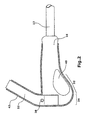
- the holding part 34 can also protrude beyond the clamping region 18 (FIG. 3), ie the length l 2 from the beginning of the clamping region 18 to the end of the holding part 34 is longer than the length l 1 of the clamping region 18 Space requirement of the bicycle handle for the bicycle handlebar 12 to reduce the distance l 2 - l 1 .
- the clamping means 20 and the holding horn 22 is preferably such designed such that its width has the length l 2 , but the clamping action is applied in particular in the clamping region 18. This can be achieved particularly easily by the horn slot 26 of the clamping means 20 having approximately the length l 1 .
- the distance d 1 of the holding part 34 to the sleeve 10 is correct, for example when the holding horn 22 is used, with the distance d 2 between the sleeve 10 and the end of the gripping member 16 match.
- the distances d 1 and d 2 may differ from each other when a clamp 20 designed as a clamping ring is used. Depending on whether the screw 28 is arranged at the top or bottom in FIG. 3, the distance d 1 or d 2 is greater than the other.
- the gripping element 16 may have a gripping part 44 which is in contact with the thumb of the cyclist when gripping.
- the gripping part 44 has, in particular, a low coefficient of friction, so that it is particularly easy to move the thumb when gripping around. This also causes chafed skin areas, blisters and the like. avoided in the area between thumb and forefinger. So that adhesion forces do not occur, especially in wet hands, the gripping part 44 has, in particular, a hydrophobic surface.
- the gripping element 16 can also have a plurality of depressions 48 (FIG. 4). With the help of the recesses 48, a particularly high friction can be generated, so that the grip of the cyclist is further improved. Such a region with a particularly high friction can be provided in particular on the underside of the support part 32, so that the risk of the hand slipping off the gripping element 16 is further reduced.
- the clamping means 20 is configured in the illustrated embodiment as a clamping ring 46.
- the clamping ring 46 corresponds to the design of the gripping element 16, ie the shape of the gripping element 16 is not interrupted by the clamping ring 46, but continued.
- the screw 28 is arranged in the illustrated embodiment in the lower region of the clamping ring 46, so that the distance d 1 greater than that Distance d 2 is executed. Further, the screw 28 is completely recessed in the clamping ring 46, so that disturbing edges are avoided.
- the support part 32 has a substantially wedge-shaped cross section (FIG. 5), so that it is directed substantially radially away from the sleeve 10.
- the gripping element 16 and the support member 32 has a recess 50 in which the pad 40 is firmly connected, for example by Molden, vulcanizing or gluing.
- the gripping member 16 may further include recesses 52 (Fig. 6) for receiving fingers. This further improves the grip of the cyclist.
- the gripping member 44 may be similar to the pad 40 by Molden, vulcanizing or gluing connected to the gripping member 16.
- a sleeve 45 is provided instead of the sleeve 10.
- the sleeve 45 preferably has a wing-shaped projection 46. This can then be overmolded by the gripping element 16. As a result, the stability of the support member 32 is increased.
- Through-openings 52 are preferably provided in the wing-shaped attachment part 46.
- the sleeve 45 itself has passage openings 54 in the cylindrical area.
- the passage openings 54 carry after injection molding with the gripping element 16 approaches of plastic.
- the sleeve 45 shown in Figure 7 has an eyelet 50 which projects into the clamping region 18 and serves to fix the clamping means 20.
- the attachment part 46 In the region of the eyelet 50, which is preferably part of the attachment part 46, the attachment part 46 is supported on the sleeve 45. As a result, the rigidity of the wing-shaped attachment part 46 is increased. In order to further increase the rigidity of the wing-shaped projection 46, the attachment part 46, starting from the sleeve 45, has a preferably steadily decreasing thickness.
- the attachment part 46 on the sleeve 45 preferably has a thickness of 3 - 4 mm.
- the attachment part 46 At the opposite free end, the attachment part 46 preferably has a thickness of 1 to 2 mm.
- the transition between the neck portion 46 and the sleeve 45 is round.
- a radius of 1.5 - 2 mm is preferably provided on both sides.
Landscapes
- Engineering & Computer Science (AREA)
- Mechanical Engineering (AREA)
- Steering Devices For Bicycles And Motorcycles (AREA)
Claims (26)
- Poignée de bicyclette, en particulier pour vélos de tourisme et vélos tout terrain, comportant
un manchon (10, 45) présentant une fente (30) de manchon et destiné à être emboîté sur un guidon (12) de vélo, le manchon (10, 45) présentant une zone de serrage (18) disposée sur un bord du manchon (10, 45),
un moyen de serrage (20) assemblé avec le manchon (10,45) dans la zone de serrage (18) et
un élément de préhension (16) assemblé avec le manchon (10, 45), caractérisée en ce que l'élément de préhension (16) présente un élément d'appui (32) en forme d'embase, orienté vers le corps et prévu pour l'appui à plat de la paume de la main, et un élément de maintien (34), l'élément de maintien (34) dépassant à l'intérieur de la zone de serrage (18), à distance du manchon (10, 45), de sorte qu'aussi bien l'élément d'appui (32) que l'élément de maintien (34) avec le moyen de serrage (20) constituent une surface commune de préhension et/ou une surface commune de maintien. - Poignée de bicyclette selon la revendication 1, caractérisée en ce que l'élément d'appui (32) forme une surface d'appui pour la paume de la main aussi bien lors de la préhension sur la surface de préhension que lors du maintien sur la surface de maintien.
- Poignée de bicyclette selon la revendication 1 ou 2, caractérisée en ce que le moyen de serrage (20) est réalisé en tant que corne de maintien (22).
- Poignée de bicyclette, en particulier pour vélos de tourisme et vélos tout terrain, comportant
un manchon (10, 45) présentant une fente (30) de manchon et destiné à être emboîté sur un guidon (12) de bicyclette, le manchon (10, 45) présentant une zone de serrage (18) disposée sur un bord du manchon (10, 45) et prévue pour la mise en place d'un moyen de serrage (20),
un élément de préhension (16) assemblé avec le manchon (10, 45) et
une corne de maintien (22) présentant le moyen de serrage (20), le moyen de serrage (20) étant assemblé avec le manchon (10,45) dans la zone de serrage (18) pour l'assemblage de la corne de maintien (22) avec le manchon (10, 45),
caractérisée en ce que l'élément de préhension (16) présente un élément d'appui (32) en forme d'embase, orienté vers le corps et prévu pour l'appui à plat de la paume de la main, l'élément d'appui (32) formant une surface d'appui pour la paume de la main aussi bien lors de la préhension de l'élément de préhension (16) que lors de la tenue de la corne de maintien (22). - Poignée de bicyclette selon la revendication 4, caractérisée en ce que l'élément de préhension (16) présente un élément de maintien (34) qui forme une unité d'une pièce avec l'élément d'appui (32) et dépasse dans la zone de serrage (18), à distance du manchon (10, 45), en particulier en étant aligné avec la corne de maintien (22).
- Poignée de bicyclette selon l'une des revendications 1 à 5, caractérisée en ce que l'élément d'appui (32) présente une surface de contact qui peut être mise en contact avec la paume de la main pendant un changement de prise correspondant au passage de l'élément de préhension (16) à la corne de maintien (22) ou au moyen de serrage (20) ou l'inverse:
- Poignée de bicyclette selon la revendication 6, caractérisée en ce que la surface de contact est réalisée en trois dimensions, de sorte qu'un pivotement de la paume de la main sur la surface de contact peut se faire pendant le changement de prise.
- Poignée de bicyclette selon l'une des revendications 1 à 7, caractérisée en ce que l'élément de maintien (34) est réalisé de telle sorte que, lors de la tenue de la corne de maintien (22) et/ou du moyen de serrage (20), il est tenu en même temps au moins en partie.
- Poignée de bicyclette selon l'une des revendications 1 à 8, caractérisée en ce que l'élément d'appui (32) est en forme de coin dans sa section transversale et, dans sa section longitudinale à l'extérieur, présente une plus grande épaisseur qu'à l'intérieur, en particulier au niveau de la transition avec l'élément de maintien (34).
- Poignée de bicyclette selon l'une des revendications 3 à 8 et selon la revendication 9, caractérisée en ce que la longueur de la corne de maintien (22) associée à celle de l'élément de maintien (34) correspond sensiblement à une largeur de main.
- Poignée de bicyclette selon l'une des revendications 1 à 10, caractérisée en ce que l'élément de maintien (34) présente un contour intérieur (36) qui correspond, au moins en partie, à un contour extérieur (38) de la corne de maintien (22) ou du moyen de serrage (20) et opère en particulier un assemblage à conjugaison de forme entre la corne de maintien (22) ou l'élément de serrage (20) et l'élément de préhension (16).
- Poignée de bicyclette selon l'une des revendications 1 à 11, caractérisée en ce que l'élément d'appui (32) présente un contour correspondant sensiblement au contour de la paume de la main.
- Poignée de bicyclette selon l'une des revendications 3 à 12, caractérisée en ce qu'aussi bien la corne de maintien (22) ou le moyen de serrage (20) que l'élément de préhension (16) sont recouverts au moins en partie par une gaine qui recouvre en particulier l'élément de serrage (20) de la corne de maintien (22).
- Poignée de bicyclette selon la revendications 13, caractérisée en ce que la gaine est réalisée, au moins en partie, en particulier sur un côté supérieur de l'élément d'appui (32), en tant qu'élément de tricot (42).
- Poignée de bicyclette selon l'une des revendications 1 à 14, caractérisée en ce que l'élément de préhension (16), en particulier l'élément d'appui (32) présente un coussin (40) réalisé dans un matériau déformable, en particulier similaire à du gel, le coussin (40) présentant une déformabilité plus élevée que l'élément de préhension (16).
- Poignée de bicyclette selon l'une des revendications 1 à 15, caractérisée en ce que la fente (30) du manchon et/ou une fente (26) de la corne prévue sur l'élément de serrage (20), sont remplies d'une matière élastomère, la matière concordant en particulier avec la matière de l'élément de préhension (16).
- Poignée de bicyclette selon l'une des revendications 1 à 16, caractérisée en ce que l'élément de préhension (16) présente une patte de liaison dépassant dans la zone de serrage (18).
- Poignée de bicyclette selon l'une des revendications 1 à 17, caractérisée en ce que l'élément de préhension (16) présente des évidements (52) pour le logement des doigts.
- Poignée de bicyclette selon l'une des revendications 1 à 18, caractérisée en ce que le moyen de serrage (20) est muni d'une vis (28) coopérant avec un filetage à trou borgne, la vis (28) étant entièrement enfoncée dans l'élément de serrage (20).
- Poignée de bicyclette selon l'une des revendications 1 à 19, caractérisée en ce que le manchon (10, 45) présente un prolongement (46) en forme d'aile qui dépasse dans l'élément d'appui (32).
- Poignée de bicyclette selon la revendication 20, caractérisée en ce que le prolongement (46) en forme d'aile dépasse dans l'élément de maintien (34).
- Poignée de bicyclette selon la revendication 20 ou 21, caractérisée en ce que le prolongement (46) en forme d'aile présente des trous de passage (52) pour l'amélioration de l'assemblage avec l'élément de préhension (16).
- Poignée de bicyclette selon l'une des revendications 1 à 22, caractérisée en ce que le manchon (10, 45) présente des trous de passage dans lesquels dépassent les pattes d'attache de l'élément de préhension (16).
- Poignée de bicyclette selon l'une des revendications 1 à 23, caractérisée en ce que le manchon (10, 45) présente un oeillet (50) dépassant dans la zone de serrage (18) pour la fixation de la position de l'élément de serrage (20).
- Poignée de bicyclette selon l'une des revendications 1 à 24, caractérisée en ce que la poignée de bicyclette est décalée par rapport au tube (12) de guidon.
- Poignée de bicyclette selon la revendication 25, caractérisée en ce que le décalage est réalisé par un épaississement (39) prévu sensiblement au milieu de l'élément de préhension (16).
Priority Applications (1)
| Application Number | Priority Date | Filing Date | Title |
|---|---|---|---|
| EP06116694A EP1712460B1 (fr) | 2003-08-25 | 2004-08-18 | Poignée de bicyclette |
Applications Claiming Priority (7)
| Application Number | Priority Date | Filing Date | Title |
|---|---|---|---|
| DE20313217 | 2003-08-25 | ||
| DE20313217U | 2003-08-25 | ||
| DE20314150 | 2003-09-11 | ||
| DE20314150U | 2003-09-11 | ||
| DE202004008297U DE202004008297U1 (de) | 2003-08-25 | 2004-05-21 | Fahrradgriff |
| DE20200400U | 2004-05-21 | ||
| PCT/EP2004/009258 WO2005021366A1 (fr) | 2003-08-25 | 2004-08-18 | Poignee de bicyclette |
Related Child Applications (1)
| Application Number | Title | Priority Date | Filing Date |
|---|---|---|---|
| EP06116694A Division EP1712460B1 (fr) | 2003-08-25 | 2004-08-18 | Poignée de bicyclette |
Publications (2)
| Publication Number | Publication Date |
|---|---|
| EP1537014A1 EP1537014A1 (fr) | 2005-06-08 |
| EP1537014B1 true EP1537014B1 (fr) | 2006-09-20 |
Family
ID=34279314
Family Applications (1)
| Application Number | Title | Priority Date | Filing Date |
|---|---|---|---|
| EP04764244A Expired - Lifetime EP1537014B1 (fr) | 2003-08-25 | 2004-08-18 | Poignee de bicyclette |
Country Status (7)
| Country | Link |
|---|---|
| US (3) | US8113087B2 (fr) |
| EP (1) | EP1537014B1 (fr) |
| AT (1) | ATE340126T1 (fr) |
| DE (1) | DE502004001529D1 (fr) |
| DK (1) | DK1537014T3 (fr) |
| ES (1) | ES2273283T3 (fr) |
| WO (1) | WO2005021366A1 (fr) |
Cited By (3)
| Publication number | Priority date | Publication date | Assignee | Title |
|---|---|---|---|---|
| DE202008011773U1 (de) * | 2008-09-04 | 2010-03-25 | Canyon Bicycles Gmbh | Fahrradgriff |
| DE202010011985U1 (de) * | 2010-08-30 | 2011-12-01 | Rti Sports Vertrieb Von Sportartikeln Gmbh | Fahrradgriff |
| DE102013204564A1 (de) * | 2013-03-15 | 2014-09-18 | Rti Sports Vertrieb Von Sportartikeln Gmbh | Spritzgussform für einen Fahrradgriff, Verfahren zur Herstellung eines Fahrradgriffs sowie Fahrradgriff |
Families Citing this family (57)
| Publication number | Priority date | Publication date | Assignee | Title |
|---|---|---|---|---|
| WO2005021366A1 (fr) * | 2003-08-25 | 2005-03-10 | Rti Sports Vertrieb Von Sportartikeln | Poignee de bicyclette |
| WO2005028727A1 (fr) * | 2003-09-22 | 2005-03-31 | Mitsubishi Chemical Functional Products, Inc. | Agregat de fibres d'alumine, et retenteur pour convertisseur catalytique comprenant cet agregat |
| DE202005000113U1 (de) * | 2005-01-07 | 2006-05-24 | Rti Sports Vertrieb Von Sportartikeln Gmbh | Seitengriffelement für Fahrradgriffe |
| DE202005013698U1 (de) | 2005-08-30 | 2007-01-11 | Rti Sports Vertrieb Von Sportartikeln Gmbh | Fahrradgriff |
| WO2007104943A2 (fr) * | 2006-03-10 | 2007-09-20 | Ultimate Sports Engineering Limited | Bicyclettes |
| US20080110291A1 (en) * | 2006-11-13 | 2008-05-15 | Vitek Christopher J | Ventilated bicycle handlebars, handlebar grips and gloves |
| CN101861264B (zh) * | 2007-11-16 | 2013-04-03 | 葛莱儿婴儿产品股份有限公司 | 手推童车及婴儿提篮系统 |
| EP2098444A1 (fr) | 2008-03-07 | 2009-09-09 | Jia-Pin Chen | Poignée de guidon |
| USD645252S1 (en) * | 2008-08-15 | 2011-09-20 | Mcneil-Ppc, Inc. | Toothbrush |
| USD658885S1 (en) * | 2008-09-30 | 2012-05-08 | Mcneil-Ppc, Inc. | Toothbrush handle |
| DE202009005939U1 (de) | 2009-04-23 | 2010-09-23 | Rti Sports Vertrieb Von Sportartikeln Gmbh | Griff mit Nut und Haltering |
| USD618534S1 (en) | 2009-06-25 | 2010-06-29 | Specialized Bicycle Components, Inc. | Handlebar grip |
| WO2011021060A1 (fr) | 2009-08-19 | 2011-02-24 | Badollet, Pascal | Poignée pour guidon d'un véhicule à deux roues |
| EP2289789A1 (fr) * | 2009-08-25 | 2011-03-02 | Life Style Metal Co., Ltd. | Ensemble démontable de guidon de bicyclette |
| DE202009011795U1 (de) * | 2009-09-01 | 2011-01-20 | Rti Sports Vertrieb Von Sportartikeln Gmbh | Fahrradgriffelement |
| US9061728B2 (en) * | 2010-03-12 | 2015-06-23 | Trek Bicycle Corporation | Bicycle handlebar and grip assembly |
| IT1399014B1 (it) * | 2010-03-24 | 2013-03-28 | Selle Royal Spa | Manopola per manubrio di bicicletta e veicoli simili e metodo per ottenerla. |
| TW201139201A (en) * | 2010-05-13 | 2011-11-16 | Velo Entpr Co Ltd | Bicycle handlebars assembly |
| CN102259681B (zh) * | 2010-05-24 | 2013-05-01 | 维乐工业股份有限公司 | 自行车握把总成 |
| DE202010011987U1 (de) * | 2010-08-30 | 2011-12-06 | Rti Sports Vertrieb Von Sportartikeln Gmbh | Fahrradgriff |
| DE202011104764U1 (de) | 2011-08-24 | 2012-11-27 | RTI Sports, Vertrieb von Sportartikeln GmbH | Fahrradgriff |
| DE202011104975U1 (de) * | 2011-08-30 | 2012-12-03 | RTI Sports, Vertrieb von Sportartikeln GmbH | Lenkerhörnchen sowie Fahrradgriff mit Lenkerhörnchen |
| CA2792886C (fr) * | 2011-10-19 | 2020-01-28 | Sidestix Ventures Inc. | Poignee ergonomique absorbant les chocs |
| DE202012007991U1 (de) | 2012-08-21 | 2013-12-04 | Rti Sports Vertrieb Von Sportartikeln Gmbh | Fahrradgriffsystem |
| DE202012006313U1 (de) | 2012-07-02 | 2013-10-08 | RTI Sports, Vertrieb von Sportartikeln GmbH | Fahrradgriffsystem |
| EP2682332B1 (fr) | 2012-07-02 | 2015-09-09 | RTI Sports Vertrieb von Sportartikeln GmbH | Système de poignée de vélo |
| DE202012012338U1 (de) | 2012-12-22 | 2014-03-24 | RTI Sports, Vertrieb von Sportartikeln GmbH | Fahrradgriffsystem |
| DE102012110074B4 (de) * | 2012-10-22 | 2019-01-24 | Klaus Mildenberger | Gefederter Fahrradgriff insbesondere in Flügelform |
| US20140116196A1 (en) * | 2012-10-31 | 2014-05-01 | Derrick Gary Rogers | Flared Grip for Bicycle or Motorcycle Handlebar |
| DE202013002491U1 (de) * | 2013-03-15 | 2014-06-17 | Rti Sports Vertrieb Von Sportartikeln Gmbh | Fahrradgriff-System |
| DE202013002492U1 (de) | 2013-03-15 | 2014-06-17 | Rti Sports Vertrieb Von Sportartikeln Gmbh | Fahrradgriff-System |
| DE202013002490U1 (de) | 2013-03-15 | 2014-06-17 | Rti Sports Vertrieb Von Sportartikeln Gmbh | Fahrradgriffsystem |
| DE202013009870U1 (de) | 2013-12-03 | 2015-03-04 | Rti Sports Vertrieb Von Sportartikeln Gmbh | Fahrradgriff |
| USD770259S1 (en) | 2015-06-24 | 2016-11-01 | Fiskars Brands, Inc. | Pick axe |
| USRE48180E1 (en) | 2015-06-24 | 2020-09-01 | Fiskars Finland Oy Ab | Sledge hammer |
| USD770258S1 (en) | 2015-06-24 | 2016-11-01 | Fiskars Brands, Inc. | Splitting maul |
| USD770255S1 (en) | 2015-06-24 | 2016-11-01 | Fiskars Brands, Inc. | Claw hammer |
| USD770256S1 (en) | 2015-06-24 | 2016-11-01 | Fiskars Brands, Inc. | Claw hammer |
| USD772671S1 (en) | 2015-06-24 | 2016-11-29 | Fiskars Brands, Inc. | Club hammer |
| USD770254S1 (en) | 2015-06-24 | 2016-11-01 | Fiskars Brands, Inc. | Claw hammer |
| USD770257S1 (en) | 2015-06-24 | 2016-11-01 | Fiskars Brands, Inc. | Sledge hammer |
| USD770875S1 (en) | 2015-06-24 | 2016-11-08 | Fiskars Brands, Inc. | Claw hammer |
| DE202016003699U1 (de) | 2016-06-14 | 2017-09-15 | Rti Sports Gmbh | Fahrradgriff |
| DE202016004728U1 (de) | 2016-08-02 | 2017-11-03 | Rti Sports Gmbh | Griffelement |
| USD896327S1 (en) | 2018-06-06 | 2020-09-15 | Nathaneal Williams Adams | Handlebar grip |
| US10766131B2 (en) | 2018-08-01 | 2020-09-08 | Alexander Deiser | Palmar grip |
| EP3817971B1 (fr) * | 2019-07-22 | 2024-05-22 | Alexander Deiser | Prise palmaire |
| GB2590717A (en) * | 2019-12-30 | 2021-07-07 | Bikesenz Ltd | Hand grip comprising an arm portion |
| DE202020102041U1 (de) | 2020-04-14 | 2021-07-15 | Ergon International Gmbh | Fahrradgriff |
| US11618529B2 (en) | 2020-06-03 | 2023-04-04 | Dextera Brakes, Llc | Grip assembly for vehicle |
| JP7435421B2 (ja) * | 2020-11-24 | 2024-02-21 | 株式会社オートネットワーク技術研究所 | コネクタ |
| DE202021104464U1 (de) | 2021-08-20 | 2022-11-22 | Dietz Gmbh | Handgriff mit Verdrehsicherung, Griffanordnung sowie Rollator aufweisend selbige |
| DE102021121627A1 (de) | 2021-08-20 | 2023-02-23 | Dietz Gmbh | Handgriff mit Verdrehsicherung, Griffanordnung sowie Rollator aufweisend selbige |
| JP2024013766A (ja) * | 2022-07-21 | 2024-02-01 | 株式会社コミネ | グリップ装着具 |
| USD1057059S1 (en) * | 2022-10-18 | 2025-01-07 | Xiamen Shouxi Sports Technology Co., Ltd | Triceps handle |
| USD1049277S1 (en) * | 2023-12-06 | 2024-10-29 | Lucas Tan | Ergonomic gym grip |
| US12296914B1 (en) * | 2024-03-21 | 2025-05-13 | Foming Bicycle Parts Co., Ltd. | Comfortable and pressure-reducing handle grip |
Family Cites Families (21)
| Publication number | Priority date | Publication date | Assignee | Title |
|---|---|---|---|---|
| US572226A (en) * | 1896-12-01 | Bicycle-handle | ||
| US4308762A (en) * | 1980-04-14 | 1982-01-05 | Oakley, Inc. | Lightened hand grip |
| US4380093A (en) * | 1980-11-28 | 1983-04-19 | Morgan Clyde R | Bicycle handlebar grip |
| DE9016065U1 (de) | 1989-12-02 | 1991-04-18 | Meinhard, Wolfgang, 2361 Bark | Wasserstoff-, Wasserstoff-Benzin(Diesel)-Verbrennungsmotor mit einer vom Verbrennungsmotor abhängigen Vorrichtung zur Eigenproduktion von Wasserstoff und Sauerstoff und deren Zuführung zum Verbrennungsmotor |
| DE9112567U1 (de) * | 1991-10-09 | 1991-12-12 | Körner, Steffen, 3000 Hannover | Lenkstangenhandgriff für Fahrräder |
| US5425285A (en) * | 1994-02-10 | 1995-06-20 | Cheng; Tien-Chu | Auxiliary handlebar assembly for bicycle |
| US5823069A (en) * | 1996-01-04 | 1998-10-20 | Harley-Davidson Motor Company | Resilient hand grip |
| US5865180A (en) * | 1996-05-24 | 1999-02-02 | Sigfrid; Tracy D. | Ergonomic pad and pad holder |
| DE19635170C1 (de) | 1996-08-30 | 1997-09-18 | Titv Greiz | Feuchteleitendes und absorbierendes Abstandsgewirke |
| DE29801916U1 (de) * | 1998-02-05 | 1998-05-28 | Grätz, Michael, 87448 Waltenhofen | Lenkergriff |
| US6003405A (en) * | 1998-07-13 | 1999-12-21 | Trek Bicycle Corporation | Bicycle handlebar bar ends |
| DE19910785B4 (de) | 1999-03-11 | 2004-12-30 | Textilforschungsinstitut Thüringen-Vogtland e.V. (TITV e.V.) | Dreidimensionales klimatisierendes Flächengebilde |
| US20040007087A1 (en) * | 2002-07-15 | 2004-01-15 | Cummings Glenn P. | Handlebar expansion sleeve/grip |
| US7028581B2 (en) * | 2002-10-05 | 2006-04-18 | Williams Thomas D | Ergonomic handgrip with separate ulnar and radial support means |
| TW560493U (en) | 2003-01-09 | 2003-11-01 | Int Bicycle Products Corp | Grip for bicycle with raised tail end |
| US6968599B2 (en) * | 2003-04-17 | 2005-11-29 | Shedrain Corporation | Pliable handle |
| US7234205B2 (en) * | 2003-04-17 | 2007-06-26 | Shedrain Corporation | Pliable handle |
| WO2005021366A1 (fr) * | 2003-08-25 | 2005-03-10 | Rti Sports Vertrieb Von Sportartikeln | Poignee de bicyclette |
| DE202004009963U1 (de) * | 2004-06-24 | 2005-10-27 | Rti Sports Vertrieb Von Sportartikeln Gmbh | Display für Fahrradgriffe |
| DE202005013698U1 (de) * | 2005-08-30 | 2007-01-11 | Rti Sports Vertrieb Von Sportartikeln Gmbh | Fahrradgriff |
| DE202009005939U1 (de) * | 2009-04-23 | 2010-09-23 | Rti Sports Vertrieb Von Sportartikeln Gmbh | Griff mit Nut und Haltering |
-
2004
- 2004-08-18 WO PCT/EP2004/009258 patent/WO2005021366A1/fr not_active Ceased
- 2004-08-18 EP EP04764244A patent/EP1537014B1/fr not_active Expired - Lifetime
- 2004-08-18 DK DK04764244T patent/DK1537014T3/da active
- 2004-08-18 DE DE502004001529T patent/DE502004001529D1/de not_active Expired - Lifetime
- 2004-08-18 AT AT04764244T patent/ATE340126T1/de active
- 2004-08-18 ES ES04764244T patent/ES2273283T3/es not_active Expired - Lifetime
- 2004-08-18 US US10/567,385 patent/US8113087B2/en active Active
-
2007
- 2007-11-19 US US11/985,885 patent/US20080072702A1/en not_active Abandoned
-
2012
- 2012-01-06 US US13/345,139 patent/US20120174698A1/en not_active Abandoned
Cited By (3)
| Publication number | Priority date | Publication date | Assignee | Title |
|---|---|---|---|---|
| DE202008011773U1 (de) * | 2008-09-04 | 2010-03-25 | Canyon Bicycles Gmbh | Fahrradgriff |
| DE202010011985U1 (de) * | 2010-08-30 | 2011-12-01 | Rti Sports Vertrieb Von Sportartikeln Gmbh | Fahrradgriff |
| DE102013204564A1 (de) * | 2013-03-15 | 2014-09-18 | Rti Sports Vertrieb Von Sportartikeln Gmbh | Spritzgussform für einen Fahrradgriff, Verfahren zur Herstellung eines Fahrradgriffs sowie Fahrradgriff |
Also Published As
| Publication number | Publication date |
|---|---|
| DE502004001529D1 (de) | 2006-11-02 |
| ES2273283T3 (es) | 2007-05-01 |
| ATE340126T1 (de) | 2006-10-15 |
| US20070089559A1 (en) | 2007-04-26 |
| DK1537014T3 (da) | 2007-02-05 |
| US20120174698A1 (en) | 2012-07-12 |
| US20080072702A1 (en) | 2008-03-27 |
| WO2005021366A1 (fr) | 2005-03-10 |
| EP1537014A1 (fr) | 2005-06-08 |
| US8113087B2 (en) | 2012-02-14 |
Similar Documents
| Publication | Publication Date | Title |
|---|---|---|
| EP1537014B1 (fr) | Poignee de bicyclette | |
| EP1712460B1 (fr) | Poignée de bicyclette | |
| EP2423089B1 (fr) | Poignée de vélo | |
| EP2423088B1 (fr) | Poignée de vélo | |
| DE102021213450A1 (de) | Hinterer umwerfer | |
| DE102019123306B4 (de) | Griffsystem | |
| EP3222507A1 (fr) | Poignée de vélo de descente | |
| EP2748056B1 (fr) | Poignée de bicyclette | |
| EP2840015B2 (fr) | Poignée de vélo | |
| EP2014544B1 (fr) | Poignée de bicyclette | |
| EP2881314B1 (fr) | Poignée de vélo | |
| EP0001646A1 (fr) | Dispositif pour guidon de bicyclettes | |
| DE102018212198A1 (de) | Fahrradgriff | |
| EP0544873B1 (fr) | Poignee de guidon | |
| WO1995029090A1 (fr) | Element de raccordement pour cornes de guidon | |
| EP1679253A2 (fr) | Elément de poignée latérale pour poignée de bicyclette | |
| DE19650347A1 (de) | Mitführeinrichtung zum Mitführen einer Sicherungseinheit an einem mobilen Objekt, Mitführeinrichtung in Verbindung mit der Schließeinheit und mobiles Objekt in Verbindung mit der Mitführeinrichtung und ggf. auch mit der Sicherungseinheit | |
| DE202024101423U1 (de) | Ergonomischer Komfort-Fahrradgriff für eine optimale Druckentlastung im Handgelenk | |
| DE2754531C2 (de) | Lenkeinrichtung für Fahrräder | |
| DE102024108139A1 (de) | Ergonomischer Komfort-Fahrradgriff für eine optimale Druckentlastung im Handgelenk | |
| DE9116448U1 (de) | Fahrradlenker | |
| DE2748027A1 (de) | Sicherheitslenkeinrichtung fuer fahrraeder und motorfahrraeder | |
| EP0952806A1 (fr) | Element de prehension concu pour la main de l'homme | |
| DE202006009077U1 (de) | Fahrradlenker | |
| DE8024946U1 (de) | Speichenrueckstrahler |
Legal Events
| Date | Code | Title | Description |
|---|---|---|---|
| PUAI | Public reference made under article 153(3) epc to a published international application that has entered the european phase |
Free format text: ORIGINAL CODE: 0009012 |
|
| 17P | Request for examination filed |
Effective date: 20050217 |
|
| AK | Designated contracting states |
Kind code of ref document: A1 Designated state(s): AT BE BG CH CY CZ DE DK EE ES FI FR GB GR HU IE IT LI LU MC NL PL PT RO SE SI SK TR |
|
| AX | Request for extension of the european patent |
Extension state: AL HR LT LV MK |
|
| GRAP | Despatch of communication of intention to grant a patent |
Free format text: ORIGINAL CODE: EPIDOSNIGR1 |
|
| GRAS | Grant fee paid |
Free format text: ORIGINAL CODE: EPIDOSNIGR3 |
|
| GRAA | (expected) grant |
Free format text: ORIGINAL CODE: 0009210 |
|
| DAX | Request for extension of the european patent (deleted) | ||
| AK | Designated contracting states |
Kind code of ref document: B1 Designated state(s): AT BE BG CH CY CZ DE DK EE ES FI FR GB GR HU IE IT LI LU MC NL PL PT RO SE SI SK TR |
|
| PG25 | Lapsed in a contracting state [announced via postgrant information from national office to epo] |
Ref country code: SK Free format text: LAPSE BECAUSE OF FAILURE TO SUBMIT A TRANSLATION OF THE DESCRIPTION OR TO PAY THE FEE WITHIN THE PRESCRIBED TIME-LIMIT Effective date: 20060920 Ref country code: SI Free format text: LAPSE BECAUSE OF FAILURE TO SUBMIT A TRANSLATION OF THE DESCRIPTION OR TO PAY THE FEE WITHIN THE PRESCRIBED TIME-LIMIT Effective date: 20060920 Ref country code: RO Free format text: LAPSE BECAUSE OF FAILURE TO SUBMIT A TRANSLATION OF THE DESCRIPTION OR TO PAY THE FEE WITHIN THE PRESCRIBED TIME-LIMIT Effective date: 20060920 Ref country code: PL Free format text: LAPSE BECAUSE OF FAILURE TO SUBMIT A TRANSLATION OF THE DESCRIPTION OR TO PAY THE FEE WITHIN THE PRESCRIBED TIME-LIMIT Effective date: 20060920 Ref country code: IT Free format text: LAPSE BECAUSE OF FAILURE TO SUBMIT A TRANSLATION OF THE DESCRIPTION OR TO PAY THE FEE WITHIN THE PRESCRIBED TIME-LIMIT;WARNING: LAPSES OF ITALIAN PATENTS WITH EFFECTIVE DATE BEFORE 2007 MAY HAVE OCCURRED AT ANY TIME BEFORE 2007. THE CORRECT EFFECTIVE DATE MAY BE DIFFERENT FROM THE ONE RECORDED. Effective date: 20060920 Ref country code: IE Free format text: LAPSE BECAUSE OF FAILURE TO SUBMIT A TRANSLATION OF THE DESCRIPTION OR TO PAY THE FEE WITHIN THE PRESCRIBED TIME-LIMIT Effective date: 20060920 Ref country code: FI Free format text: LAPSE BECAUSE OF FAILURE TO SUBMIT A TRANSLATION OF THE DESCRIPTION OR TO PAY THE FEE WITHIN THE PRESCRIBED TIME-LIMIT Effective date: 20060920 Ref country code: CZ Free format text: LAPSE BECAUSE OF FAILURE TO SUBMIT A TRANSLATION OF THE DESCRIPTION OR TO PAY THE FEE WITHIN THE PRESCRIBED TIME-LIMIT Effective date: 20060920 |
|
| REG | Reference to a national code |
Ref country code: GB Ref legal event code: FG4D Free format text: NOT ENGLISH |
|
| REG | Reference to a national code |
Ref country code: CH Ref legal event code: EP |
|
| REG | Reference to a national code |
Ref country code: IE Ref legal event code: FG4D Free format text: LANGUAGE OF EP DOCUMENT: GERMAN |
|
| REF | Corresponds to: |
Ref document number: 502004001529 Country of ref document: DE Date of ref document: 20061102 Kind code of ref document: P |
|
| PG25 | Lapsed in a contracting state [announced via postgrant information from national office to epo] |
Ref country code: SE Free format text: LAPSE BECAUSE OF FAILURE TO SUBMIT A TRANSLATION OF THE DESCRIPTION OR TO PAY THE FEE WITHIN THE PRESCRIBED TIME-LIMIT Effective date: 20061220 Ref country code: BG Free format text: LAPSE BECAUSE OF FAILURE TO SUBMIT A TRANSLATION OF THE DESCRIPTION OR TO PAY THE FEE WITHIN THE PRESCRIBED TIME-LIMIT Effective date: 20061220 |
|
| GBT | Gb: translation of ep patent filed (gb section 77(6)(a)/1977) |
Effective date: 20061229 |
|
| REG | Reference to a national code |
Ref country code: DK Ref legal event code: T3 |
|
| PG25 | Lapsed in a contracting state [announced via postgrant information from national office to epo] |
Ref country code: PT Free format text: LAPSE BECAUSE OF FAILURE TO SUBMIT A TRANSLATION OF THE DESCRIPTION OR TO PAY THE FEE WITHIN THE PRESCRIBED TIME-LIMIT Effective date: 20070312 |
|
| REG | Reference to a national code |
Ref country code: IE Ref legal event code: FD4D |
|
| ET | Fr: translation filed | ||
| REG | Reference to a national code |
Ref country code: ES Ref legal event code: FG2A Ref document number: 2273283 Country of ref document: ES Kind code of ref document: T3 |
|
| PLBE | No opposition filed within time limit |
Free format text: ORIGINAL CODE: 0009261 |
|
| STAA | Information on the status of an ep patent application or granted ep patent |
Free format text: STATUS: NO OPPOSITION FILED WITHIN TIME LIMIT |
|
| 26N | No opposition filed |
Effective date: 20070621 |
|
| REG | Reference to a national code |
Ref country code: CH Ref legal event code: PCAR Free format text: ISLER & PEDRAZZINI AG;POSTFACH 1772;8027 ZUERICH (CH) |
|
| BERE | Be: lapsed |
Owner name: RTI SPORTS VERTRIEB VON SPORTARTIKELN G.M.B.H. Effective date: 20070831 |
|
| PG25 | Lapsed in a contracting state [announced via postgrant information from national office to epo] |
Ref country code: MC Free format text: LAPSE BECAUSE OF NON-PAYMENT OF DUE FEES Effective date: 20070831 Ref country code: GR Free format text: LAPSE BECAUSE OF FAILURE TO SUBMIT A TRANSLATION OF THE DESCRIPTION OR TO PAY THE FEE WITHIN THE PRESCRIBED TIME-LIMIT Effective date: 20061221 |
|
| PG25 | Lapsed in a contracting state [announced via postgrant information from national office to epo] |
Ref country code: EE Free format text: LAPSE BECAUSE OF FAILURE TO SUBMIT A TRANSLATION OF THE DESCRIPTION OR TO PAY THE FEE WITHIN THE PRESCRIBED TIME-LIMIT Effective date: 20060920 |
|
| PG25 | Lapsed in a contracting state [announced via postgrant information from national office to epo] |
Ref country code: BE Free format text: LAPSE BECAUSE OF NON-PAYMENT OF DUE FEES Effective date: 20070831 |
|
| PGRI | Patent reinstated in contracting state [announced from national office to epo] |
Ref country code: IT Effective date: 20081001 |
|
| PG25 | Lapsed in a contracting state [announced via postgrant information from national office to epo] |
Ref country code: LU Free format text: LAPSE BECAUSE OF NON-PAYMENT OF DUE FEES Effective date: 20070818 Ref country code: CY Free format text: LAPSE BECAUSE OF FAILURE TO SUBMIT A TRANSLATION OF THE DESCRIPTION OR TO PAY THE FEE WITHIN THE PRESCRIBED TIME-LIMIT Effective date: 20060920 |
|
| PG25 | Lapsed in a contracting state [announced via postgrant information from national office to epo] |
Ref country code: HU Free format text: LAPSE BECAUSE OF FAILURE TO SUBMIT A TRANSLATION OF THE DESCRIPTION OR TO PAY THE FEE WITHIN THE PRESCRIBED TIME-LIMIT Effective date: 20070321 Ref country code: TR Free format text: LAPSE BECAUSE OF FAILURE TO SUBMIT A TRANSLATION OF THE DESCRIPTION OR TO PAY THE FEE WITHIN THE PRESCRIBED TIME-LIMIT Effective date: 20060920 |
|
| PGFP | Annual fee paid to national office [announced via postgrant information from national office to epo] |
Ref country code: ES Payment date: 20110224 Year of fee payment: 7 |
|
| REG | Reference to a national code |
Ref country code: DE Ref legal event code: R008 Ref document number: 502004001529 Country of ref document: DE |
|
| REG | Reference to a national code |
Ref country code: DE Ref legal event code: R039 Ref document number: 502004001529 Country of ref document: DE Effective date: 20110926 |
|
| PGFP | Annual fee paid to national office [announced via postgrant information from national office to epo] |
Ref country code: IT Payment date: 20110824 Year of fee payment: 8 |
|
| REG | Reference to a national code |
Ref country code: DE Ref legal event code: R082 Ref document number: 502004001529 Country of ref document: DE Representative=s name: VON KREISLER SELTING WERNER, DE |
|
| REG | Reference to a national code |
Ref country code: DE Ref legal event code: R082 Ref document number: 502004001529 Country of ref document: DE Representative=s name: DOMPATENT VON KREISLER SELTING WERNER - PARTNE, DE Effective date: 20120424 Ref country code: DE Ref legal event code: R082 Ref document number: 502004001529 Country of ref document: DE Representative=s name: VON KREISLER SELTING WERNER - PARTNERSCHAFT VO, DE Effective date: 20120424 Ref country code: DE Ref legal event code: R082 Ref document number: 502004001529 Country of ref document: DE Representative=s name: VON KREISLER SELTING WERNER, DE Effective date: 20120424 Ref country code: DE Ref legal event code: R081 Ref document number: 502004001529 Country of ref document: DE Owner name: ERGON INTERNATIONAL GMBH, DE Free format text: FORMER OWNER: RTI SPORTS VERTRIEB VON SPORTARTIKELN GMBH, 56220 URMITZ, DE Effective date: 20120424 Ref country code: DE Ref legal event code: R081 Ref document number: 502004001529 Country of ref document: DE Owner name: RTI SPORTS GMBH, DE Free format text: FORMER OWNER: RTI SPORTS VERTRIEB VON SPORTARTIKELN GMBH, 56220 URMITZ, DE Effective date: 20120424 Ref country code: DE Ref legal event code: R081 Ref document number: 502004001529 Country of ref document: DE Owner name: RTI SPORTS VERTRIEB VON SPORTARTIKELN GMBH, DE Free format text: FORMER OWNER: RTI SPORTS VERTRIEB VON SPORTARTIKELN GMBH, 56220 URMITZ, DE Effective date: 20120424 |
|
| REG | Reference to a national code |
Ref country code: ES Ref legal event code: FD2A Effective date: 20121207 |
|
| PG25 | Lapsed in a contracting state [announced via postgrant information from national office to epo] |
Ref country code: ES Free format text: LAPSE BECAUSE OF NON-PAYMENT OF DUE FEES Effective date: 20110819 |
|
| REG | Reference to a national code |
Ref country code: DE Ref legal event code: R097 Ref document number: 502004001529 Country of ref document: DE |
|
| PG25 | Lapsed in a contracting state [announced via postgrant information from national office to epo] |
Ref country code: IT Free format text: LAPSE BECAUSE OF FAILURE TO SUBMIT A TRANSLATION OF THE DESCRIPTION OR TO PAY THE FEE WITHIN THE PRESCRIBED TIME-LIMIT Effective date: 20120818 |
|
| REG | Reference to a national code |
Ref country code: DE Ref legal event code: R040 Ref document number: 502004001529 Country of ref document: DE Effective date: 20130325 |
|
| PGFP | Annual fee paid to national office [announced via postgrant information from national office to epo] |
Ref country code: CH Payment date: 20130826 Year of fee payment: 10 Ref country code: DK Payment date: 20130819 Year of fee payment: 10 Ref country code: AT Payment date: 20130821 Year of fee payment: 10 |
|
| PGFP | Annual fee paid to national office [announced via postgrant information from national office to epo] |
Ref country code: FR Payment date: 20130820 Year of fee payment: 10 |
|
| REG | Reference to a national code |
Ref country code: DK Ref legal event code: EBP Effective date: 20140831 |
|
| REG | Reference to a national code |
Ref country code: CH Ref legal event code: PL |
|
| REG | Reference to a national code |
Ref country code: AT Ref legal event code: MM01 Ref document number: 340126 Country of ref document: AT Kind code of ref document: T Effective date: 20140818 |
|
| PG25 | Lapsed in a contracting state [announced via postgrant information from national office to epo] |
Ref country code: CH Free format text: LAPSE BECAUSE OF NON-PAYMENT OF DUE FEES Effective date: 20140831 Ref country code: LI Free format text: LAPSE BECAUSE OF NON-PAYMENT OF DUE FEES Effective date: 20140831 |
|
| PG25 | Lapsed in a contracting state [announced via postgrant information from national office to epo] |
Ref country code: AT Free format text: LAPSE BECAUSE OF NON-PAYMENT OF DUE FEES Effective date: 20140818 |
|
| REG | Reference to a national code |
Ref country code: FR Ref legal event code: ST Effective date: 20150430 |
|
| PG25 | Lapsed in a contracting state [announced via postgrant information from national office to epo] |
Ref country code: DK Free format text: LAPSE BECAUSE OF NON-PAYMENT OF DUE FEES Effective date: 20140831 |
|
| PG25 | Lapsed in a contracting state [announced via postgrant information from national office to epo] |
Ref country code: FR Free format text: LAPSE BECAUSE OF NON-PAYMENT OF DUE FEES Effective date: 20140901 |
|
| REG | Reference to a national code |
Ref country code: DE Ref legal event code: R082 Ref document number: 502004001529 Country of ref document: DE Representative=s name: DOMPATENT VON KREISLER SELTING WERNER - PARTNE, DE Ref country code: DE Ref legal event code: R081 Ref document number: 502004001529 Country of ref document: DE Owner name: ERGON INTERNATIONAL GMBH, DE Free format text: FORMER OWNER: RTI SPORTS VERTRIEB VON SPORTARTIKELN GMBH, 56070 KOBLENZ, DE Ref country code: DE Ref legal event code: R081 Ref document number: 502004001529 Country of ref document: DE Owner name: RTI SPORTS GMBH, DE Free format text: FORMER OWNER: RTI SPORTS VERTRIEB VON SPORTARTIKELN GMBH, 56070 KOBLENZ, DE |
|
| REG | Reference to a national code |
Ref country code: DE Ref legal event code: R082 Ref document number: 502004001529 Country of ref document: DE Representative=s name: DOMPATENT VON KREISLER SELTING WERNER - PARTNE, DE Ref country code: DE Ref legal event code: R081 Ref document number: 502004001529 Country of ref document: DE Owner name: ERGON INTERNATIONAL GMBH, DE Free format text: FORMER OWNER: RTI SPORTS GMBH, 56070 KOBLENZ, DE |
|
| REG | Reference to a national code |
Ref country code: NL Ref legal event code: PD Owner name: ERGON INTERNATIONAL GMBH; DE Free format text: DETAILS ASSIGNMENT: CHANGE OF OWNER(S), DEMERGER; FORMER OWNER NAME: RTI SPORTS GMBH Effective date: 20190125 Ref country code: NL Ref legal event code: HC Owner name: RTI SPORTS GMBH; DE Free format text: DETAILS ASSIGNMENT: CHANGE OF OWNER(S), CHANGE OF OWNER(S) NAME; FORMER OWNER NAME: RTI SPORTS VERTRIEB VON SPORTARTIKELN GMBH Effective date: 20190125 |
|
| REG | Reference to a national code |
Ref country code: GB Ref legal event code: 732E Free format text: REGISTERED BETWEEN 20191128 AND 20191204 |
|
| PGFP | Annual fee paid to national office [announced via postgrant information from national office to epo] |
Ref country code: NL Payment date: 20220822 Year of fee payment: 19 |
|
| PGFP | Annual fee paid to national office [announced via postgrant information from national office to epo] |
Ref country code: GB Payment date: 20220824 Year of fee payment: 19 |
|
| P01 | Opt-out of the competence of the unified patent court (upc) registered |
Effective date: 20230502 |
|
| P02 | Opt-out of the competence of the unified patent court (upc) changed |
Effective date: 20230804 |
|
| PGFP | Annual fee paid to national office [announced via postgrant information from national office to epo] |
Ref country code: DE Payment date: 20230829 Year of fee payment: 20 |
|
| REG | Reference to a national code |
Ref country code: NL Ref legal event code: MM Effective date: 20230901 |
|
| GBPC | Gb: european patent ceased through non-payment of renewal fee |
Effective date: 20230818 |
|
| PG25 | Lapsed in a contracting state [announced via postgrant information from national office to epo] |
Ref country code: NL Free format text: LAPSE BECAUSE OF NON-PAYMENT OF DUE FEES Effective date: 20230901 |
|
| PG25 | Lapsed in a contracting state [announced via postgrant information from national office to epo] |
Ref country code: NL Free format text: LAPSE BECAUSE OF NON-PAYMENT OF DUE FEES Effective date: 20230901 |
|
| PG25 | Lapsed in a contracting state [announced via postgrant information from national office to epo] |
Ref country code: GB Free format text: LAPSE BECAUSE OF NON-PAYMENT OF DUE FEES Effective date: 20230818 |
|
| PG25 | Lapsed in a contracting state [announced via postgrant information from national office to epo] |
Ref country code: GB Free format text: LAPSE BECAUSE OF NON-PAYMENT OF DUE FEES Effective date: 20230818 |
|
| REG | Reference to a national code |
Ref country code: DE Ref legal event code: R071 Ref document number: 502004001529 Country of ref document: DE |