EP1538000A2 - Tintenpatrone - Google Patents
Tintenpatrone Download PDFInfo
- Publication number
- EP1538000A2 EP1538000A2 EP04257552A EP04257552A EP1538000A2 EP 1538000 A2 EP1538000 A2 EP 1538000A2 EP 04257552 A EP04257552 A EP 04257552A EP 04257552 A EP04257552 A EP 04257552A EP 1538000 A2 EP1538000 A2 EP 1538000A2
- Authority
- EP
- European Patent Office
- Prior art keywords
- chamber
- passage
- ink
- ink cartridge
- cartridge
- Prior art date
- Legal status (The legal status is an assumption and is not a legal conclusion. Google has not performed a legal analysis and makes no representation as to the accuracy of the status listed.)
- Withdrawn
Links
- 230000008602 contraction Effects 0.000 claims abstract description 3
- 239000012530 fluid Substances 0.000 claims description 15
- 238000005192 partition Methods 0.000 claims description 8
- 230000007423 decrease Effects 0.000 description 7
- 229920006395 saturated elastomer Polymers 0.000 description 5
- JOYRKODLDBILNP-UHFFFAOYSA-N Ethyl urethane Chemical compound CCOC(N)=O JOYRKODLDBILNP-UHFFFAOYSA-N 0.000 description 1
- 230000005587 bubbling Effects 0.000 description 1
- 230000003247 decreasing effect Effects 0.000 description 1
- 239000002657 fibrous material Substances 0.000 description 1
- 239000006261 foam material Substances 0.000 description 1
- 239000011148 porous material Substances 0.000 description 1
Images


Classifications
-
- B—PERFORMING OPERATIONS; TRANSPORTING
- B41—PRINTING; LINING MACHINES; TYPEWRITERS; STAMPS
- B41J—TYPEWRITERS; SELECTIVE PRINTING MECHANISMS, i.e. MECHANISMS PRINTING OTHERWISE THAN FROM A FORME; CORRECTION OF TYPOGRAPHICAL ERRORS
- B41J2/00—Typewriters or selective printing mechanisms characterised by the printing or marking process for which they are designed
- B41J2/005—Typewriters or selective printing mechanisms characterised by the printing or marking process for which they are designed characterised by bringing liquid or particles selectively into contact with a printing material
- B41J2/01—Ink jet
- B41J2/17—Ink jet characterised by ink handling
- B41J2/175—Ink supply systems ; Circuit parts therefor
- B41J2/17503—Ink cartridges
- B41J2/17513—Inner structure
Definitions
- a second known ink cartridge is disclosed in EP-A-0581531.
- This known ink cartridge comprises an ink tank with a first chamber and a second chamber separated by a partition, the partition terminating above the floor of the tank to provide a gap forming a communication port for fluid communication between the two chambers.
- the cartridge also has an air vent and an ink supply outlet, both of which are in the wall of the first chamber.
- a porous member fills the first chamber. There is no porous member in the second chamber, which forms an open volume for storage of ink.
- a disadvantage of the known two chamber cartridge over the known single chamber cartridge however is in the situation of decreased atmospheric pressure or increased temperature. As described, as the ink is withdrawn from the cartridge, a volume of air enters the second chamber. If atmospheric pressure decreases or the temperature increases, the volume of air trapped above the ink in the second chamber will expand and exert a pressure on the ink which can lead to leakage of ink through the ink outlet port, and hence from the print head of the printer in which the cartridge is situated, or can lead to poor quality printing.
- an ink cartridge comprising an ink tank, the ink tank comprising a first chamber, the cartridge including an air vent and an ink supply outlet both opening into the first chamber the cartridge further including means defining a volume in which air and ink can collect to form a buffer against expansion or contraction of ink and air in the first chamber to prevent leakage from the cartridge.
- an ink cartridge comprising an ink tank, the ink tank comprising first and second chambers connected for fluid communication at a low level, the cartridge including an air vent and an ink supply outlet, the air vent and ink supply outlet both opening into the first chamber, characterised in that the cartridge further includes means defining a passage from the first chamber to the second chamber, the entrance to the passage from the first chamber being at a higher level than the exit from the passage into the second chamber.
- a capillary active member may cover the fluid communication connection between the first and second chambers.
- a capillary active member may cover the entrance to the passage.
- a capillary active member may block the ink supply outlet.
- a capillary active member or negative pressure producing member is provided in the first chamber and covers at least one of the fluid communication connection between the first and second chambers, the entrance to the passage and the ink supply outlet.
- a capillary active member or negative pressure producing member is provided in the first chamber and covers the fluid communication connection between the first and second chambers and the ink supply outlet.
- a capillary active member may be provided in the first chamber and may cover the ink supply outlet and the entrance to the passage.
- the exit from the passage into the second chamber may be on the far side of the second chamber from the first chamber.
- an ink cartridge comprising an ink tank, the ink tank comprising first and second chambers connected for fluid communication at a low level, the cartridge including an air vent and an ink supply outlet, the air vent and ink supply outlet both opening into the first chamber, characterised in that the cartridge further includes means defining a passage from the first chamber to the second chamber, the exit from the passage into the second chamber being on the far side of the second chamber from the first chamber.
- the passage preferably extends upwardly from the entrance thereto.
- the passage forms a volume in which air can collect.
- the passage thus preferably includes a part which is above the entrance to the passage from the first chamber and also preferably above the exit from the passage into the second chamber.
- the wall of the second chamber may define at least part of one side of the passage.
- the outer wall of the tank may define at least part of one side of the passage.
- the second chamber may include at least one partition, the partition having an aperture at a low level.
- the aperture may be below the level of the passage exit into the second chamber. In this way, the volume of trapped air can be reduced because the second chamber is divided.
- Figure 10 is a perspective view of the main part of the cartridge shown in Figures 1 to 9;
- Figures 12 to 23 each show a side elevation of the main part of the cartridge in the second embodiment of the invention with different indications of ink level.
- the cartridge 10 of the first embodiment of the invention is made in two parts 6, 8.
- the main part 6 of the cartridge 10 is generally tray shaped.
- the other part 8 of the cartridge 10 is generally flat and rectangular with a peg 4 at each comer to be received in circular recesses 11 defined in the main part 6 of the cartridge 10.
- the cartridge 10 of the first embodiment comprises an ink tank 12 with an ink supply outlet tube 14 and an air vent 16.
- the ink tank 12 contains a number of internal walls.
- First internal wall 18 depends from the top of the tank 12 to a level about three quarters of the way down into the cartridge. The wall 18 does not quite reach the top 20 of the ink tank 12.
- Another wall 22 just below the top 20 of the ink tank 12 extends from the top of the wall 18 to the end 24 of the ink tank 12.
- a third wall 26 extends upwardly from adjacent the floor 28 of the ink tank 12 parallel to the end wall 24 and turns through 90° to run parallel to the second wall 22 before turning through 90° again to run down parallel to the first wall 18 before turning through 90° to extend until it is directly beneath the first wall 18, then turning downwards over a short distance to terminate above the floor 28 of the ink tank 12.
- the two ends 30, 32 of the wall 26 are at about the same height.
- a passage 33 is defined between the wall 26 and the first wall 18, second wall 22 and end wall 24. The passage 33 is of constant cross section.
- a first chamber 34 is defined on the other side of the first wall 18 from the wall 26, and the wall 26 together with the floor 28 of the ink tank 12 defines a second chamber 36.
- the second chamber 36 is divided by a central divider 38 which depends from the wall 26 vertically down to adjacent the floor 27 half way between the two upright sections of the wall 26.
- the lower end 40 of the wall 38 terminates above the floor 28 at a level lower than the ends 30, 32 of the wall 26.
- the second chamber 36 and the passage 33 constitute open volumes.
- Two porous members 42, 44 occupy the first chamber 34.
- the air vent 16 opens into the first chamber 34 at the top of the first chamber 34 and leads into a space 46 formed above a horizontal rib 48 which extends from the end wall 50 (opposite the end wall 24).
- the second porous member 44 has a lower pore size than the first porous member 42 and may be made of an extruded fibrous material, the fibres having no particular orientation overall.
- the ink supply outlet 14 extends from the floor 28 of the ink tank 12 and leads out of the first chamber 34.
- a filter layer 54 is bonded to the lower side of the second porous member 44.
- the second porous member 44 is sized such that it fills the space in the first chamber 34 beneath the first porous member 42 with the filter layer 54 lying on the floor 28 in the first chamber 34 of the ink tank 12 over the ink supply outlet port 14.
- the second porous member 44 thus covers the gap 56 between the end of the wall 26 and the floor 28 which is the communication port between the first and second chambers 34, 36.
- the second porous member 44 also covers the entrance 58 to the passage 33, namely, the gap between the lower end 52 of the first wall 18 and the part of the wall 36 is directly below it.
- the second porous member 44 together with the filter layer 54 also covers the entirety of the upper end of the ink supply outlet port 14.
- Each internal wall 18, 22, 26, 38 is mainly defined in the main part 6, but short walls 18a, 22a, 26a and 38a are formed on the other part 8 of the cartridge 10 and the two parts of the walls fit together.
- the cartridge 10 is fitted into a printer [not shown] so that the ink withdrawal needle [not shown] of the printer is received in the ink supply outlet port 14 for withdrawal of ink from the cartridge 10 for supply to the print head of the printer.
- the printer may be an ink jet printer.
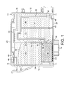
- Figures 1 to 7 show how ink is withdrawn from the cartridge 10 of the first embodiment of the invention.
- Figure 1 shows a new, unused cartridge.
- the second chamber 36 and the passage 33 are full of ink, the second porous member 44 is saturated with ink and the first porous member 42 is substantially saturated with ink, the ink level 60 being close to the top of the first porous member 42.
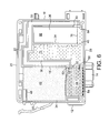
- the level of ink 70 will drop until it reaches the lower end 40 of the divider 38 at which point air will begin to bubble into the second sub-chamber 72 of the second chamber 66 as shown in Fig. 6. Because the lower end 30 of the wall 26 at the exit from the passages above the height of the lower end 40 of the divider 38, the first sub-chamber 66 of the second chamber 36 is now in air communication with the passage 33 and thereby through the first chamber 34 to the air vent 16 and atmosphere.
- the second sub-chamber 72 will fill with air and empty of ink in the same way as the first chamber 66.
- the ink level reaches the lower end 32 of the wall 26 forming the communication port between the first and second chambers 34, 36, ink will continue to be withdrawn from the second chamber 36 into the lower, second porous member 44 because of the capillarity of the second porous member 44.
- the second chamber 36 can therefore be completely or almost completely emptied so that finally the only ink remaining in the cartridge 10 is in the second porous member 44, as shown in Figure 7.
- the printer may be arranged to stop drawing ink from the cartridge before the cartridge is emptied of ink.
- the passage 33 and the second chamber 36 represent open volumes for ink storage, increasing the capacity of the cartridge, and that these volumes can be effectively emptied such that they represent an efficient way of storing ink in a cartridge of a given size.
- the level of ink 74 is above the exit 64 from the passage 33. If when the cartridge is in that condition, there is a decrease in atmospheric pressure, or an increase in temperature, then the air in the cartridge will expand. The air in the first chamber 34 can escape through the air vent 16.
- the air in the passage 33 can expand into the first chamber 34 through the passage entrance 58 and pressure can be relieved through leakage through the air vent 16.
- the pocket of air 68 is trapped however and as it expands it will exert pressure on the ink below it.
- the movement of the ink is shown in Figure 8 where the original level of the ink 74, 76 is shown as a dotted line and the level of ink 78, 80 after movement is shown as a solid line.
- the ink level 74 in the first sub-chamber 66 drops to the level 78.
- ink moves back up the passage so that the ink level rises from 76 to 80 in the passage 33 to compensate for the movement of ink in the first sub-chamber 66.
- the passage 33 acts as a buffer, allowing the ink to rise and fall in a controlled manner as the trapped air expands or contracts. This prevents the ink from being forced into the second porous member 44 from which it might travel to the print head causing leakage or dripping at the print head. It is seen that, in entering the passage 33 the ink is faced with an open volume to occupy, rather than the tortuous volume represented by the high capillary second porous member 44, and so the passage 33 forms a preferential route for movement of the ink.
- Figure 9 shows the situation where there is a pocket of air 82 trapped at the top of the second sub-chamber 72. If there is a decrease in atmospheric pressure, or an increase in ambient temperature, then the air in the pocket 82 will expand exerting pressure on the ink below it so that the ink level 84 will drop in the second sub-chamber 72 from the level shown by the dotted line to the level shown by the solid line, while the ink level to the other side of the divider 38 rises from the dotted line to the solid line 86.
- the increase in the height of the ink level to the other side of the divider 38 does not yet intercept the lower end 30 of the wall 26 at the exit 64 from the passage. If the ink level should be pushed further so that it intercepts the end 30 of the wall 26, then air will be trapped above the ink in the first sub-chamber 66 and any further expansion will be taken up by movement of ink back up the passage 33.
- the divider 38 need not be provided. This does mean however that the volume of air that can be trapped at any one time is larger than with the divided chamber so that the consequent volume expansion and therefore movement of ink along the passage will be of greater magnitude compared with the embodiment with the divided chamber.
- two or more dividers 38 may be provided. It will be appreciated that each divider should preferably terminate at a lower level than the end of the wall 30 defining the upper edge of the exit from the passage, and also at a lower level than the preceding divider. This will reduce the volume of air that can be trapped at any one time, but each divider occupies a volume which could otherwise be occupied by ink, so the ink capacity of the cartridge is reduced.
- first and second porous members 42, 44 of the first embodiment may be replaced by a single porous member of constant porosity.
- the use of two porous members of different porosity as in the embodiment described in relation to the drawings however results in better emptying of the cartridge as the higher capillarity of the second porous member will draw ink out of the lower porosity of the first porous member 42.
- the passage 33 of this embodiment does not extend over the top of the second chamber 36 and there is no divider 38 in the second chamber 36.
- the wall 26 also does not include the kink towards the lower end 32.
- the lower end 32 of the wall 26 lies adjacent but spaced from the floor 28 leaving a communication gap 56 as before, although the gap 56 is smaller as the lower end 32 of the wall 26 is closer to the floor 28 in this embodiment.
- the wall 26 includes an aperture 90.
- the aperture 90 is above the level of the lower end 52 of the wall 18, but is closer to that level than to the top of the passage 33. Indeed the aperture 90 is only slightly above the level of the lower end 52 of the wall 18.
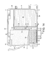
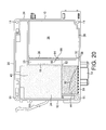
- Figures 12 to 20 show how ink is withdrawn from the cartridge 10 of this embodiment of the invention.
- Figure 12 shows a new, unused cartridge.
- the second chamber 36 and the passage 33 are full of ink, the second porous member 44 is saturated with ink and the first porous member 42 is substantially saturated with ink, the ink level 60 being close to the top of the first porous member 42.
- the high capillarity of the second, lower porous member 44 resists movement of ink out of the second porous member 44 such that ink is taken preferentially from the open volume constituted by the passage 33 and the second chamber 36.
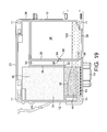
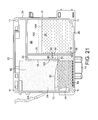
- the level of ink 70 will continue to drop, and when the ink level reaches the lower wall 98 defining the lower side of the aperture 90, the ink level to either side of the wall 26 will become the same, as shown in Fig. 18, as the passage 33 and the upper part of the second chamber 36 are in air communication.
- the ink level will continue to fall as shown in Fig. 19.
- the ink level reaches the lower end 32 of the wall 26 forming the communication port 56 between the first and second chambers 34, 36, ink will continue to be withdrawn from the second chamber 36 into the lower, second porous member 44 because of the capillarity of the second porous member 44.
- the second chamber 36 can therefore be completely or almost completely emptied so that finally the only ink remaining in the cartridge 10 is in the second porous member 44, as shown in Figure 20.
- the printer may be arranged to stop drawing ink from the cartridge before the cartridge is emptied of ink.
- the passage 33 and the second chamber 36 represent open volumes for ink storage, increasing the capacity of the cartridge, and that these volumes can be effectively emptied such that they represent an efficient way of storing ink in a cartridge of a given size.
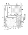
- Figures 22 and 23 show the situation where ambient temperature decreases or atmospheric pressure increases.
- the air in the passage 33 and second chamber 36 contracts so that the ink level 102, 100 rises to new levels 106, 108 shown in solid lines in Figure 22.
- the ink level in the first chamber 34 drops and so air bubbles from the first chamber 34 into the passage 33 as shown in Figure 22.
- the ambient temperature decrease or atmospheric pressure increase is of sufficient magnitude, then the air bubbling into the passage 33 will cause the ink level 106 there to fall to the level of the top wall 94 of the aperture 90 and air will bubble through the aperture 90 into the second chamber 36.
Landscapes
- Ink Jet (AREA)
Applications Claiming Priority (6)
| Application Number | Priority Date | Filing Date | Title |
|---|---|---|---|
| GB0328013 | 2003-12-03 | ||
| GB0328013A GB0328013D0 (en) | 2003-12-03 | 2003-12-03 | An ink cartridge |
| GB0329001 | 2003-12-15 | ||
| GB0329001A GB0329001D0 (en) | 2003-12-03 | 2003-12-15 | An ink cartridge |
| GB0404432 | 2004-02-27 | ||
| GB0404432A GB0404432D0 (en) | 2003-12-03 | 2004-02-27 | An ink cartridge |
Publications (2)
| Publication Number | Publication Date |
|---|---|
| EP1538000A2 true EP1538000A2 (de) | 2005-06-08 |
| EP1538000A3 EP1538000A3 (de) | 2010-02-24 |
Family
ID=34068758
Family Applications (1)
| Application Number | Title | Priority Date | Filing Date |
|---|---|---|---|
| EP04257552A Withdrawn EP1538000A3 (de) | 2003-12-03 | 2004-12-03 | Tintenpatrone |
Country Status (3)
| Country | Link |
|---|---|
| EP (1) | EP1538000A3 (de) |
| GB (1) | GB2409434B (de) |
| WO (1) | WO2005053960A1 (de) |
Cited By (2)
| Publication number | Priority date | Publication date | Assignee | Title |
|---|---|---|---|---|
| WO2012034500A1 (zh) * | 2010-09-13 | 2012-03-22 | 珠海天威飞马打印耗材有限公司 | 一种背压式墨盒 |
| CN107187207A (zh) * | 2013-10-23 | 2017-09-22 | 精工爱普生株式会社 | 液体收容容器及液体喷射装置 |
Families Citing this family (6)
| Publication number | Priority date | Publication date | Assignee | Title |
|---|---|---|---|---|
| GB2427853A (en) | 2005-06-30 | 2007-01-10 | Dynamic Cassette Int | An ink cartridge and a memory device |
| US8684505B2 (en) | 2012-03-19 | 2014-04-01 | Hewlett-Packard Development Company, L.P. | Vent path for a liquid container |
| JP2017177778A (ja) * | 2016-03-31 | 2017-10-05 | ブラザー工業株式会社 | タンク |
| CN111730983B (zh) * | 2016-03-31 | 2023-01-13 | 兄弟工业株式会社 | 罐 |
| JP6891398B2 (ja) * | 2016-03-31 | 2021-06-18 | ブラザー工業株式会社 | タンク |
| CN107264050B (zh) * | 2016-03-31 | 2020-06-26 | 兄弟工业株式会社 | 罐 |
Citations (1)
| Publication number | Priority date | Publication date | Assignee | Title |
|---|---|---|---|---|
| EP0581531A1 (de) | 1992-07-24 | 1994-02-02 | Canon Kabushiki Kaisha | Tintenbehälter und Tintenstrahlaufzeichnungsgerät mit einem solchen Behälter |
Family Cites Families (11)
| Publication number | Priority date | Publication date | Assignee | Title |
|---|---|---|---|---|
| US5010354A (en) * | 1989-11-28 | 1991-04-23 | Hewlett-Packard Company | Ink jet pen with improved volumetric efficiency |
| JPH08207304A (ja) * | 1994-11-03 | 1996-08-13 | Xerox Corp | インク供給カートリッジ及びインクジェットプリンタ |
| MX9801290A (es) * | 1997-02-19 | 1998-11-30 | Canon Cabushiki Kaisha | Envase de liquido para cabeza de chorron de tinta. |
| JP3286210B2 (ja) * | 1997-06-19 | 2002-05-27 | キヤノン株式会社 | インクタンク |
| JP3287791B2 (ja) * | 1997-07-30 | 2002-06-04 | キヤノン株式会社 | 液体収容室を有する液体収容容器への液体充填方法及び液体充填装置 |
| US6257712B1 (en) * | 1997-11-14 | 2001-07-10 | Brother Kogyo Kabushiki Kaisha | Ink feeder |
| JPH11320908A (ja) * | 1998-04-06 | 1999-11-24 | Xerox Corp | インク供給容器 |
| JP3278410B2 (ja) * | 1998-05-11 | 2002-04-30 | キヤノン株式会社 | 液体収納容器、該容器の製造方法、該容器のパッケージ、該容器と記録ヘッドとを一体化したインクジェットヘッドカートリッジ及び液体吐出記録装置 |
| JP3647326B2 (ja) * | 1999-08-24 | 2005-05-11 | キヤノン株式会社 | 液体収納容器、液体吐出機構およびインクジェット記録装置 |
| US6663234B2 (en) * | 2001-06-11 | 2003-12-16 | Xerox Corporation | Ink cartridge providing improved ink supply |
| KR100421972B1 (ko) * | 2002-05-16 | 2004-03-11 | 삼성전자주식회사 | 잉크 카트리지 |
-
2004
- 2004-12-03 WO PCT/GB2004/005104 patent/WO2005053960A1/en not_active Ceased
- 2004-12-03 EP EP04257552A patent/EP1538000A3/de not_active Withdrawn
- 2004-12-03 GB GB0426649A patent/GB2409434B/en not_active Expired - Fee Related
Patent Citations (1)
| Publication number | Priority date | Publication date | Assignee | Title |
|---|---|---|---|---|
| EP0581531A1 (de) | 1992-07-24 | 1994-02-02 | Canon Kabushiki Kaisha | Tintenbehälter und Tintenstrahlaufzeichnungsgerät mit einem solchen Behälter |
Cited By (3)
| Publication number | Priority date | Publication date | Assignee | Title |
|---|---|---|---|---|
| WO2012034500A1 (zh) * | 2010-09-13 | 2012-03-22 | 珠海天威飞马打印耗材有限公司 | 一种背压式墨盒 |
| CN107187207A (zh) * | 2013-10-23 | 2017-09-22 | 精工爱普生株式会社 | 液体收容容器及液体喷射装置 |
| CN107187207B (zh) * | 2013-10-23 | 2019-01-18 | 精工爱普生株式会社 | 液体收容容器及液体喷射装置 |
Also Published As
| Publication number | Publication date |
|---|---|
| WO2005053960A1 (en) | 2005-06-16 |
| EP1538000A3 (de) | 2010-02-24 |
| GB2409434A (en) | 2005-06-29 |
| GB2409434B (en) | 2007-08-22 |
| GB0426649D0 (en) | 2005-01-05 |
Similar Documents
| Publication | Publication Date | Title |
|---|---|---|
| US5010354A (en) | Ink jet pen with improved volumetric efficiency | |
| EP0577439B1 (de) | Tintenbehälter | |
| US5877794A (en) | Method for supplying ink to an ink jet recording device | |
| US5821965A (en) | Ink supply unit and recorder | |
| EP0493058A2 (de) | Verfahren und Gerät für die Tintenversorgung eines Tintenstrahldruckers | |
| EP1538000A2 (de) | Tintenpatrone | |
| KR19980042466A (ko) | 액체 토출용 용기 | |
| JP2005342993A (ja) | 液体収納容器および該液体収納容器を用いた記録装置 | |
| JPH1110899A (ja) | インクタンク | |
| US5821964A (en) | Cartridge for supplying liquid to a print head | |
| US20080106582A1 (en) | Liquid tank | |
| KR20000053434A (ko) | 잉크 서플라이 용기 및 용기내에 잉크를 저장하는 방법 | |
| US20100253754A1 (en) | Ink cartridge, especially for an ink jet printer | |
| US20040189755A1 (en) | Authentication of a remote user to a host in data communication system | |
| US6663234B2 (en) | Ink cartridge providing improved ink supply | |
| TWI342832B (en) | Colour print cartridge | |
| US8517526B2 (en) | Print cartridge | |
| US7478901B1 (en) | Container having fluidically segregated compartments | |
| US20100277554A1 (en) | Ink cartridge, especially for an ink jet printer | |
| US20070139491A1 (en) | Fluid storage container | |
| US20020075366A1 (en) | Liquid ink tank with integral capillary | |
| JP3244806B2 (ja) | インクジェットカートリッジ | |
| JP4289180B2 (ja) | 廃インクタンク | |
| US6527383B1 (en) | Anti-bubble shelf in an ink tank | |
| JPH1058699A (ja) | インクカートリッジ |
Legal Events
| Date | Code | Title | Description |
|---|---|---|---|
| PUAI | Public reference made under article 153(3) epc to a published international application that has entered the european phase |
Free format text: ORIGINAL CODE: 0009012 |
|
| AK | Designated contracting states |
Kind code of ref document: A2 Designated state(s): AT BE BG CH CY CZ DE DK EE ES FI FR GB GR HU IE IS IT LI LT LU MC NL PL PT RO SE SI SK TR |
|
| AX | Request for extension of the european patent |
Extension state: AL BA HR LV MK YU |
|
| PUAL | Search report despatched |
Free format text: ORIGINAL CODE: 0009013 |
|
| AK | Designated contracting states |
Kind code of ref document: A3 Designated state(s): AT BE BG CH CY CZ DE DK EE ES FI FR GB GR HU IE IS IT LI LT LU MC NL PL PT RO SE SI SK TR |
|
| AX | Request for extension of the european patent |
Extension state: AL BA HR LV MK YU |
|
| AKX | Designation fees paid |
Designated state(s): AT BE BG CH CY CZ DE DK EE ES FI FR GB GR HU IE IS IT LI LT LU MC NL PL PT RO SE SI SK TR |
|
| STAA | Information on the status of an ep patent application or granted ep patent |
Free format text: STATUS: THE APPLICATION IS DEEMED TO BE WITHDRAWN |
|
| 18D | Application deemed to be withdrawn |
Effective date: 20100701 |