EP1538331A1 - Soupape d'injection de carburant - Google Patents
Soupape d'injection de carburant Download PDFInfo
- Publication number
- EP1538331A1 EP1538331A1 EP04105050A EP04105050A EP1538331A1 EP 1538331 A1 EP1538331 A1 EP 1538331A1 EP 04105050 A EP04105050 A EP 04105050A EP 04105050 A EP04105050 A EP 04105050A EP 1538331 A1 EP1538331 A1 EP 1538331A1
- Authority
- EP
- European Patent Office
- Prior art keywords
- fuel injection
- injection valve
- valve according
- recess
- chamber
- Prior art date
- Legal status (The legal status is an assumption and is not a legal conclusion. Google has not performed a legal analysis and makes no representation as to the accuracy of the status listed.)
- Granted
Links
- 239000000446 fuel Substances 0.000 title claims abstract description 57
- 238000002347 injection Methods 0.000 title claims abstract description 47
- 239000007924 injection Substances 0.000 title claims abstract description 47
- 238000007789 sealing Methods 0.000 claims description 11
- 239000012528 membrane Substances 0.000 claims description 8
- 230000007423 decrease Effects 0.000 claims description 3
- 229920001971 elastomer Polymers 0.000 claims description 3
- 239000000806 elastomer Substances 0.000 claims description 3
- 229920002449 FKM Polymers 0.000 claims description 2
- 239000007788 liquid Substances 0.000 claims 1
- 239000012530 fluid Substances 0.000 description 6
- 238000002485 combustion reaction Methods 0.000 description 4
- 230000006835 compression Effects 0.000 description 4
- 238000007906 compression Methods 0.000 description 4
- 238000004519 manufacturing process Methods 0.000 description 4
- 230000001419 dependent effect Effects 0.000 description 3
- 238000011161 development Methods 0.000 description 3
- 230000018109 developmental process Effects 0.000 description 3
- 238000012546 transfer Methods 0.000 description 3
- 238000003466 welding Methods 0.000 description 3
- 238000013461 design Methods 0.000 description 2
- 238000003825 pressing Methods 0.000 description 2
- 230000003044 adaptive effect Effects 0.000 description 1
- 238000006243 chemical reaction Methods 0.000 description 1
- 238000010276 construction Methods 0.000 description 1
- 230000008878 coupling Effects 0.000 description 1
- 238000010168 coupling process Methods 0.000 description 1
- 238000005859 coupling reaction Methods 0.000 description 1
- 238000005553 drilling Methods 0.000 description 1
- 238000007373 indentation Methods 0.000 description 1
- 230000016507 interphase Effects 0.000 description 1
- 239000000463 material Substances 0.000 description 1
- 238000000034 method Methods 0.000 description 1
- 239000000203 mixture Substances 0.000 description 1
- 230000003716 rejuvenation Effects 0.000 description 1
- 238000007493 shaping process Methods 0.000 description 1
- 238000003860 storage Methods 0.000 description 1
- 238000013519 translation Methods 0.000 description 1
Images
Classifications
-
- F—MECHANICAL ENGINEERING; LIGHTING; HEATING; WEAPONS; BLASTING
- F02—COMBUSTION ENGINES; HOT-GAS OR COMBUSTION-PRODUCT ENGINE PLANTS
- F02M—SUPPLYING COMBUSTION ENGINES IN GENERAL WITH COMBUSTIBLE MIXTURES OR CONSTITUENTS THEREOF
- F02M51/00—Fuel-injection apparatus characterised by being operated electrically
- F02M51/06—Injectors peculiar thereto with means directly operating the valve needle
- F02M51/0603—Injectors peculiar thereto with means directly operating the valve needle using piezoelectric or magnetostrictive operating means
-
- F—MECHANICAL ENGINEERING; LIGHTING; HEATING; WEAPONS; BLASTING
- F02—COMBUSTION ENGINES; HOT-GAS OR COMBUSTION-PRODUCT ENGINE PLANTS
- F02M—SUPPLYING COMBUSTION ENGINES IN GENERAL WITH COMBUSTIBLE MIXTURES OR CONSTITUENTS THEREOF
- F02M61/00—Fuel-injectors not provided for in groups F02M39/00 - F02M57/00 or F02M67/00
- F02M61/04—Fuel-injectors not provided for in groups F02M39/00 - F02M57/00 or F02M67/00 having valves, e.g. having a plurality of valves in series
- F02M61/08—Fuel-injectors not provided for in groups F02M39/00 - F02M57/00 or F02M67/00 having valves, e.g. having a plurality of valves in series the valves opening in direction of fuel flow
-
- F—MECHANICAL ENGINEERING; LIGHTING; HEATING; WEAPONS; BLASTING
- F02—COMBUSTION ENGINES; HOT-GAS OR COMBUSTION-PRODUCT ENGINE PLANTS
- F02M—SUPPLYING COMBUSTION ENGINES IN GENERAL WITH COMBUSTIBLE MIXTURES OR CONSTITUENTS THEREOF
- F02M61/00—Fuel-injectors not provided for in groups F02M39/00 - F02M57/00 or F02M67/00
- F02M61/16—Details not provided for in, or of interest apart from, the apparatus of groups F02M61/02 - F02M61/14
- F02M61/166—Selection of particular materials
-
- F—MECHANICAL ENGINEERING; LIGHTING; HEATING; WEAPONS; BLASTING
- F02—COMBUSTION ENGINES; HOT-GAS OR COMBUSTION-PRODUCT ENGINE PLANTS
- F02M—SUPPLYING COMBUSTION ENGINES IN GENERAL WITH COMBUSTIBLE MIXTURES OR CONSTITUENTS THEREOF
- F02M61/00—Fuel-injectors not provided for in groups F02M39/00 - F02M57/00 or F02M67/00
- F02M61/16—Details not provided for in, or of interest apart from, the apparatus of groups F02M61/02 - F02M61/14
- F02M61/167—Means for compensating clearance or thermal expansion
-
- F—MECHANICAL ENGINEERING; LIGHTING; HEATING; WEAPONS; BLASTING
- F02—COMBUSTION ENGINES; HOT-GAS OR COMBUSTION-PRODUCT ENGINE PLANTS
- F02M—SUPPLYING COMBUSTION ENGINES IN GENERAL WITH COMBUSTIBLE MIXTURES OR CONSTITUENTS THEREOF
- F02M2200/00—Details of fuel-injection apparatus, not otherwise provided for
- F02M2200/16—Sealing of fuel injection apparatus not otherwise provided for
-
- F—MECHANICAL ENGINEERING; LIGHTING; HEATING; WEAPONS; BLASTING
- F02—COMBUSTION ENGINES; HOT-GAS OR COMBUSTION-PRODUCT ENGINE PLANTS
- F02M—SUPPLYING COMBUSTION ENGINES IN GENERAL WITH COMBUSTIBLE MIXTURES OR CONSTITUENTS THEREOF
- F02M2200/00—Details of fuel-injection apparatus, not otherwise provided for
- F02M2200/70—Linkage between actuator and actuated element, e.g. between piezoelectric actuator and needle valve or pump plunger
- F02M2200/703—Linkage between actuator and actuated element, e.g. between piezoelectric actuator and needle valve or pump plunger hydraulic
- F02M2200/707—Linkage between actuator and actuated element, e.g. between piezoelectric actuator and needle valve or pump plunger hydraulic with means for avoiding fuel contact with actuators, e.g. isolating actuators by using bellows or diaphragms
Definitions
- the invention is based on a fuel injection valve according to the preamble of the main claim.
- a disadvantage of this known prior art is that leakage through sealing rings is not completely avoided can be and the fuel injectors thereby a have a shorter lifespan.
- the seal by Corrugated pipe seals greatly increase the amount of hydraulic medium and thus the temperature-dependent behavior of the coupler. In addition, the size and the manufacturing cost elevated.
- the fuel injection valve according to the invention with the characterizing features of the main claim has In contrast, the advantage that the hydraulic medium of Kopplers is permanently sealed and the space as well the production costs are reduced.
- Couplers In a first development engages or protrudes Diameter entry into a recess, wherein in a further development of the recess in a enlarging the volume of the coupler. This allows the Couplers are built compact and the bias, with the the flexible section acts on the hydraulic medium, be favorably influenced.
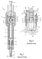
- the fuel injection valve 1 shown in Fig. 1 is in the form of a fuel injection valve 1 for Fuel injection systems of mixture compression, spark-ignited internal combustion engines running.
- the Fuel injector 1 is particularly suitable for direct injection of fuel into one illustrated combustion chamber of an internal combustion engine.
- the fuel injection valve 1 comprises a housing 2, in which one provided with an Aktorumspritzung 3 piezoelectric or magnetostrictive actuator 4 arranged is.
- the actuator 4 can by means of an electrical line 5, at which a protruding from the housing 2 electrical Terminal 6 may be formed, an electrical voltage be supplied.
- the actuator 4 is supported on the inflow side a master piston 9 of a hydraulic coupler 7 and downstream of an actuator head 8 from.
- the hydraulic Coupler 7 further comprises a slave piston 10, a Compression spring 11, which the hydraulic coupler 7 with a Bias biased, and a compensation chamber 12, which is filled with a hydraulic medium. Of the Fuel is fed centrally via an inlet 14.
- Valve needle 16 Downstream of the actuator head 8 is an actuating body 15th arranged, which acts on a valve needle 16.
- the Valve needle 16 has at its downstream end a Valve-closing body 17 on. This works with a Valve seat surface 18, which on a nozzle body 19th is formed, together to form a sealing seat.
- a Return spring 20 acts on the valve needle 16 so that the fuel injection valve 1 in the de-energized state of Actuator 4 remains in the closed state. Continues to provide they after the injection phase for the provision of the Valve needle 16.
- the nozzle body 19 is by means of a weld 21 in one Inner housing 22 fixed, which the actuator 4 against the Fuel seals.
- the fuel flows from the inlet 14 between the housing 2 and the inner housing 22 for Sealing seat.
- Fig. 2 shows a similar to that shown in Fig. 1 Coupler constructed coupler 7.
- Hydraulic couplers 7 in fuel injection valves 1 are usually on the one hand for conversion or translation of the stroke of Actuator 4 on the valve needle 16 and / or on the other hand to Compensation of temperature-induced changes in length of the actuator. 4 and the housing 2 designed. The latter will, as in the Embodiment shown by means of a Second medium coupler executed coupler 7 realized which is not in contact with the fuel Contains hydraulic medium.
- the hydraulic fluid fills the Compensation space 12 and a between master piston 9 and Slave piston 10 trained coupler volume 23, which with the compensation chamber 12 is connected via a throttle 24.
- the compensation chamber 12 is inside and outside of the Slave piston 10 is arranged, wherein the two parts by a transverse bore 31 are connected to each other and the outside lying part of the expansion chamber 12 by means of a as a corrugated pipe seal executed flexible portion 13th opposite to the fuel injection valve 1 is sealed by flowing fuel.
- at Temperature changes will be hydraulic medium between the Coupler volume 23 via the throttle 24 with the compensation chamber 12 exchanged.
- the necessary filling pressure is over in the slave piston 10 in a pressure storage chamber 32nd arranged compression spring 11 applied. This is between a first closure body 25 and a second Closure body 26 arranged, the former a groove 27th with a sealing ring 28 disposed therein for sealing the Coupling space 12 has.
- a disadvantage of the described design of the Fuel injection valve 1 and the hydraulic coupler 7 is in particular that the leakage losses at the in the groove 27 arranged sealing ring 28 are relatively high. This sets the endurance resistance of the fuel injection valve 1, since the hydraulic medium on the sealing ring 28 with time leaking into the accumulator chamber 32 and thus the through the compression spring 11 decreases the applied bias.
- undesirable behavior in the Fuel injection valve 1 over the life by virtue of The complicated construction is the production of the coupler 7 very expensive and the size increased unfavorably.
- Moreover, in particular by the shape of the flexible Section a relatively large capacity of the hydraulic medium necessary. But this increases the temperature dependence by the temperature expansion.
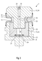
- FIG 3 shows a first exemplary embodiment of a coupler 7 for an inventively designed Fuel injector 1.
- the slave piston 10 engages a piston-shaped second slave section 35 in the in essential cylindrical master piston 9 a.
- the Slave piston 10 and the second slave section 35 are in Master piston 9 axially movable with a guide gap 38th guided.
- the guide gap 38 is relatively small, wherein the through the guide gap 38 in operation passing amount Hydraulic medium is negligible small.
- the guide gap 38 a Exercise throttle function.
- the slave piston 10th from a first slave section 34 and a second Nehmerabrough 35 wherein in other embodiments the slave piston 10 can also be made in one piece.
- the first slave section 34 is cylindrical and tapered extending from a diameter that is about the diameter of the Master piston 9 corresponds, stepwise in the direction of Master piston 9, and the second slave section 35.
- the rejuvenated part of the first Nehmerabrough 34 partially engages coaxially in the second Nehmerabrough 35 and is fixed there immovable, for example, by pressing or welding.
- a flexible section 13 which is tubular and elastic and a U-shaped diameter retraction 33 is circumferentially, arranged in the region of the recess 39.
- the U-shaped Diameter indentation 33 protrudes into the recess 39.
- the flexible section 13 In the area of the upper end is the flexible section 13 on the circumference of the first slave section 34, for example cohesive, hermetically sealed.
- the flexible portion 13 In the area of his the lower end, the flexible portion 13 is circumferentially of the Master piston 9 hermetically sealed.
- the slave piston 10 has a centered channel 29, which merges into a compensation channel 36 in the course and out through a ball 30, which after filling the coupler 7 with hydraulic medium for closing the Channel 29 is inserted, is closed.
- a compensation channel 36 which in this embodiment is designed as a stepped bore ends at his the Coupler volume 23 facing the end of a throttle plate 37, the at least one as a relatively small hole executed, centered throttle 24 has.
- the Throttle 24 opens into the coupler volume 23rd
- the transverse bore 31 Approximately at the height of the passage of the channel 29 in the Compensation channels 36 is the transverse bore 31, which also by other shaping methods than drilling can be produced.
- the throttle plate 37 is in the Surface of the second slave section 35 embedded and for example, by welding material fit to the second Nehmerabites 35 added.
- the transverse bore 31 connects via the throttle 24, the coupler volume 23 with the compensation chamber 12th
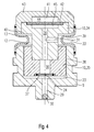
- Fig. 4 shows a second embodiment of a Inventive fuel injector 1 in the area of the coupler 7, similar to the first embodiment Fig. 3.
- the channel 29 is arranged in the master piston 9. Of the Channel 29 opens directly into the coupler volume 23.
- Der Compensation channel 36 connects the coupler volume 23, the Compensation space 12 and a chamber 41 with each other.
- the chamber 41 is formed in the slave piston 10, wherein in this Embodiment, the chamber 41 by a first Recess 44, which centers in one the first Nehmerabites 34 above and laterally comprehensive attachment 43 is arranged, and by a second recess 45, the centered at the upper end of the first slave section 34 is formed, is formed.
- the recesses 44, 45 lie with the interposition of a Membrane 42 hydraulically close to each other and tight form the chamber 41.
- the membrane 42 is made for example, an elastomer and shares the chamber 41st hermetically sealed in the first recess 44 and the second Recess 45.
- the second recess 45 is above the Compensation channel 36 with the coupler volume 23 in conjunction.
- the first recess 44 is, for example, with a gas filled with pressure and thus exerts on the hydraulic medium a pressure off.
- the Coupler internal pressure via an additional in the chamber 41st arranged spring can be generated, so that the interior 41st is depressurized.
- the membrane 42 is elastic and consists of an elastomer, for example from Viton. That to Slave piston 10 belonging attachment 43 is, for example by pressing and / or welding with the first Nehmerabites 34 connected.
- the flexible section 13 is with its upper end on the radially outer surface of the attachment 43 hermetically sealed.
- the invention is not limited to those shown Embodiments limited and for any designs of fuel injection valves 1, in particular for Fuel injection valves 1 for self-igniting Internal combustion engines and / or inward opening Fuel injection valves, suitable.
- the Exemplary embodiments can be combined with one another as desired.
Landscapes
- Engineering & Computer Science (AREA)
- Chemical & Material Sciences (AREA)
- Combustion & Propulsion (AREA)
- Mechanical Engineering (AREA)
- General Engineering & Computer Science (AREA)
- Fuel-Injection Apparatus (AREA)
Applications Claiming Priority (2)
| Application Number | Priority Date | Filing Date | Title |
|---|---|---|---|
| DE10357454 | 2003-12-03 | ||
| DE2003157454 DE10357454A1 (de) | 2003-12-03 | 2003-12-03 | Brennstoffeinspritzventil |
Publications (2)
| Publication Number | Publication Date |
|---|---|
| EP1538331A1 true EP1538331A1 (fr) | 2005-06-08 |
| EP1538331B1 EP1538331B1 (fr) | 2007-05-30 |
Family
ID=34442509
Family Applications (1)
| Application Number | Title | Priority Date | Filing Date |
|---|---|---|---|
| EP20040105050 Expired - Lifetime EP1538331B1 (fr) | 2003-12-03 | 2004-10-14 | Soupape d'injection de carburant |
Country Status (2)
| Country | Link |
|---|---|
| EP (1) | EP1538331B1 (fr) |
| DE (2) | DE10357454A1 (fr) |
Cited By (6)
| Publication number | Priority date | Publication date | Assignee | Title |
|---|---|---|---|---|
| EP1591656A3 (fr) * | 2004-04-26 | 2005-11-23 | Isuzu Motors Limited | Méchanisme d'absortion de l'expansion différentielle et une soupape d'injection de combustible comprenant celui-ci |
| EP1780405A1 (fr) * | 2005-10-26 | 2007-05-02 | Siemens Aktiengesellschaft | Injecteur, dispositif de compensation pour l'injecteur et moyen de transmission de pression pour le dispositif de compensation |
| EP1813805A1 (fr) * | 2006-01-27 | 2007-08-01 | Siemens VDO Automotive S.p.A. | Ensemble de compensation pour un injecteur |
| EP1918571A1 (fr) * | 2006-11-02 | 2008-05-07 | Siemens Aktiengesellschaft | Injecteur de dosage de fluide |
| EP2078846A1 (fr) * | 2008-01-14 | 2009-07-15 | Continental Automotive GmbH | Agencement d'actionneur et soupape à injection |
| US20150014436A1 (en) * | 2012-02-27 | 2015-01-15 | Robert Bosch Gmbh | Valve for Metering Fluid |
Families Citing this family (1)
| Publication number | Priority date | Publication date | Assignee | Title |
|---|---|---|---|---|
| EP2235251B1 (fr) | 2007-12-21 | 2018-03-07 | BSH Hausgeräte GmbH | Dispositif de repassage |
Citations (6)
| Publication number | Priority date | Publication date | Assignee | Title |
|---|---|---|---|---|
| US4858439A (en) * | 1987-03-03 | 1989-08-22 | Toyota Jidosha Kabushiki Kaisha | Device for varying a stroke |
| WO1993006625A1 (fr) * | 1991-09-27 | 1993-04-01 | Siemens Aktiengesellschaft | Transformateur hydraulique de deplacement pour l'organe piezoelectrique d'actionnement d'une soupape d'admission |
| US20020139863A1 (en) * | 2000-10-11 | 2002-10-03 | Jack Lorraine | Compensator assembly having a flexible diaphragm and an internal filling tube for a fuel injector and method |
| WO2003031799A1 (fr) * | 2001-10-02 | 2003-04-17 | Robert Bosch Gmbh | Soupape d'injection de carburant |
| DE10149914A1 (de) * | 2001-10-10 | 2003-04-24 | Bosch Gmbh Robert | Brennstoffeinspritzventil |
| EP1452727A1 (fr) * | 2003-02-27 | 2004-09-01 | Robert Bosch Gmbh | Injecteur de carburant |
Family Cites Families (3)
| Publication number | Priority date | Publication date | Assignee | Title |
|---|---|---|---|---|
| EP0477400B1 (fr) * | 1990-09-25 | 2000-04-26 | Siemens Aktiengesellschaft | Dispositif compensateur de tolérance dans la direction de mouvement du transformateur de déplacement d'un dispositif d'actionnement piézoélectrique |
| DE19962177A1 (de) * | 1999-12-22 | 2001-07-12 | Siemens Ag | Hydraulische Vorrichtung zum Übertragen einer Aktorbewegung |
| DE10159749A1 (de) * | 2001-12-05 | 2003-06-12 | Bosch Gmbh Robert | Brennstoffeinspritzventil |
-
2003
- 2003-12-03 DE DE2003157454 patent/DE10357454A1/de not_active Withdrawn
-
2004
- 2004-10-14 DE DE200450003933 patent/DE502004003933D1/de not_active Expired - Fee Related
- 2004-10-14 EP EP20040105050 patent/EP1538331B1/fr not_active Expired - Lifetime
Patent Citations (6)
| Publication number | Priority date | Publication date | Assignee | Title |
|---|---|---|---|---|
| US4858439A (en) * | 1987-03-03 | 1989-08-22 | Toyota Jidosha Kabushiki Kaisha | Device for varying a stroke |
| WO1993006625A1 (fr) * | 1991-09-27 | 1993-04-01 | Siemens Aktiengesellschaft | Transformateur hydraulique de deplacement pour l'organe piezoelectrique d'actionnement d'une soupape d'admission |
| US20020139863A1 (en) * | 2000-10-11 | 2002-10-03 | Jack Lorraine | Compensator assembly having a flexible diaphragm and an internal filling tube for a fuel injector and method |
| WO2003031799A1 (fr) * | 2001-10-02 | 2003-04-17 | Robert Bosch Gmbh | Soupape d'injection de carburant |
| DE10149914A1 (de) * | 2001-10-10 | 2003-04-24 | Bosch Gmbh Robert | Brennstoffeinspritzventil |
| EP1452727A1 (fr) * | 2003-02-27 | 2004-09-01 | Robert Bosch Gmbh | Injecteur de carburant |
Cited By (8)
| Publication number | Priority date | Publication date | Assignee | Title |
|---|---|---|---|---|
| EP1591656A3 (fr) * | 2004-04-26 | 2005-11-23 | Isuzu Motors Limited | Méchanisme d'absortion de l'expansion différentielle et une soupape d'injection de combustible comprenant celui-ci |
| US7198202B2 (en) | 2004-04-26 | 2007-04-03 | Isuzu Motors Limited | Differential expansion absorption mechanism and fuel injection valve comprising same |
| EP1780405A1 (fr) * | 2005-10-26 | 2007-05-02 | Siemens Aktiengesellschaft | Injecteur, dispositif de compensation pour l'injecteur et moyen de transmission de pression pour le dispositif de compensation |
| EP1813805A1 (fr) * | 2006-01-27 | 2007-08-01 | Siemens VDO Automotive S.p.A. | Ensemble de compensation pour un injecteur |
| EP1918571A1 (fr) * | 2006-11-02 | 2008-05-07 | Siemens Aktiengesellschaft | Injecteur de dosage de fluide |
| EP2078846A1 (fr) * | 2008-01-14 | 2009-07-15 | Continental Automotive GmbH | Agencement d'actionneur et soupape à injection |
| US20150014436A1 (en) * | 2012-02-27 | 2015-01-15 | Robert Bosch Gmbh | Valve for Metering Fluid |
| US9470198B2 (en) * | 2012-02-27 | 2016-10-18 | Robert Bosch Gmbh | Valve for metering fluid |
Also Published As
| Publication number | Publication date |
|---|---|
| DE10357454A1 (de) | 2005-07-07 |
| DE502004003933D1 (de) | 2007-07-12 |
| EP1538331B1 (fr) | 2007-05-30 |
Similar Documents
| Publication | Publication Date | Title |
|---|---|---|
| EP1115970B1 (fr) | Soupape d'injection de carburant | |
| EP1423600B1 (fr) | Soupape d'injection de carburant | |
| EP1456526B1 (fr) | Soupape d'injection de carburant | |
| EP1538331B1 (fr) | Soupape d'injection de carburant | |
| EP1601868B1 (fr) | Soupape d'injection de carburant | |
| EP1378657B1 (fr) | Injecteur de carburant | |
| DE10217594A1 (de) | Brennstoffeinspritzventil | |
| EP1472452B1 (fr) | Soupape d'injection de carburant | |
| EP1519035B1 (fr) | Soupape d'injection de combustible | |
| EP1714026B1 (fr) | Soupape d'injection de carburant | |
| EP1519036B1 (fr) | Injecteur de carburant | |
| EP1452727B1 (fr) | Injecteur de carburant | |
| DE10353641B4 (de) | Brennstoffeinspritzventil | |
| EP2539575B1 (fr) | Injecteur de carburant avec un ensemble aiguille d'injecteur | |
| EP1620645B1 (fr) | Soupape d'injection de carburant sans perte | |
| DE102006013958B4 (de) | Brennstoffeinspritzventil | |
| EP2243949A1 (fr) | Injecteur de carburant | |
| DE10321693A1 (de) | Brennstoffeinspritzventil | |
| EP1450034B1 (fr) | Injecteur de carburant | |
| EP2820291A1 (fr) | Soupape de dosage de fluide | |
| DE102005035671B4 (de) | Kraftstoffinjektor für eine Brennkraftmaschine | |
| DE102013220875A1 (de) | Ventil zum Zumessen von Fluid | |
| DE10259730A1 (de) | Brennstoffeinspritzventil | |
| DE10254985A1 (de) | Ventil zum Steuern von Flüssigkeiten mit einem Düsen- und einem Steuermodul | |
| DE102005045892A1 (de) | Direktbetriebener, außenöffnender Injektor |
Legal Events
| Date | Code | Title | Description |
|---|---|---|---|
| PUAI | Public reference made under article 153(3) epc to a published international application that has entered the european phase |
Free format text: ORIGINAL CODE: 0009012 |
|
| AK | Designated contracting states |
Kind code of ref document: A1 Designated state(s): AT BE BG CH CY CZ DE DK EE ES FI FR GB GR HU IE IT LI LU MC NL PL PT RO SE SI SK TR |
|
| AX | Request for extension of the european patent |
Extension state: AL HR LT LV MK |
|
| 17P | Request for examination filed |
Effective date: 20051208 |
|
| AKX | Designation fees paid |
Designated state(s): DE FR GB IT |
|
| 17Q | First examination report despatched |
Effective date: 20060202 |
|
| GRAP | Despatch of communication of intention to grant a patent |
Free format text: ORIGINAL CODE: EPIDOSNIGR1 |
|
| GRAS | Grant fee paid |
Free format text: ORIGINAL CODE: EPIDOSNIGR3 |
|
| GRAA | (expected) grant |
Free format text: ORIGINAL CODE: 0009210 |
|
| AK | Designated contracting states |
Kind code of ref document: B1 Designated state(s): DE FR GB IT |
|
| REG | Reference to a national code |
Ref country code: GB Ref legal event code: FG4D Free format text: NOT ENGLISH |
|
| REF | Corresponds to: |
Ref document number: 502004003933 Country of ref document: DE Date of ref document: 20070712 Kind code of ref document: P |
|
| GBT | Gb: translation of ep patent filed (gb section 77(6)(a)/1977) |
Effective date: 20070829 |
|
| ET | Fr: translation filed | ||
| PLBE | No opposition filed within time limit |
Free format text: ORIGINAL CODE: 0009261 |
|
| STAA | Information on the status of an ep patent application or granted ep patent |
Free format text: STATUS: NO OPPOSITION FILED WITHIN TIME LIMIT |
|
| PGFP | Annual fee paid to national office [announced via postgrant information from national office to epo] |
Ref country code: FR Payment date: 20071019 Year of fee payment: 4 |
|
| 26N | No opposition filed |
Effective date: 20080303 |
|
| PGFP | Annual fee paid to national office [announced via postgrant information from national office to epo] |
Ref country code: DE Payment date: 20071219 Year of fee payment: 4 |
|
| GBPC | Gb: european patent ceased through non-payment of renewal fee |
Effective date: 20081014 |
|
| REG | Reference to a national code |
Ref country code: FR Ref legal event code: ST Effective date: 20090630 |
|
| PG25 | Lapsed in a contracting state [announced via postgrant information from national office to epo] |
Ref country code: DE Free format text: LAPSE BECAUSE OF NON-PAYMENT OF DUE FEES Effective date: 20090501 |
|
| PG25 | Lapsed in a contracting state [announced via postgrant information from national office to epo] |
Ref country code: FR Free format text: LAPSE BECAUSE OF NON-PAYMENT OF DUE FEES Effective date: 20081031 |
|
| PG25 | Lapsed in a contracting state [announced via postgrant information from national office to epo] |
Ref country code: GB Free format text: LAPSE BECAUSE OF NON-PAYMENT OF DUE FEES Effective date: 20081014 |
|
| PGFP | Annual fee paid to national office [announced via postgrant information from national office to epo] |
Ref country code: IT Payment date: 20071031 Year of fee payment: 4 |