EP1539509B1 - Procede et systeme d'antenne a bande pour pneumatique a identification par radiofrequence - Google Patents
Procede et systeme d'antenne a bande pour pneumatique a identification par radiofrequence Download PDFInfo
- Publication number
- EP1539509B1 EP1539509B1 EP03787966A EP03787966A EP1539509B1 EP 1539509 B1 EP1539509 B1 EP 1539509B1 EP 03787966 A EP03787966 A EP 03787966A EP 03787966 A EP03787966 A EP 03787966A EP 1539509 B1 EP1539509 B1 EP 1539509B1
- Authority
- EP
- European Patent Office
- Prior art keywords
- antenna
- conductive
- rfid chip
- slot
- tyre
- Prior art date
- Legal status (The legal status is an assumption and is not a legal conclusion. Google has not performed a legal analysis and makes no representation as to the accuracy of the status listed.)
- Expired - Lifetime
Links
Images



Classifications
-
- H—ELECTRICITY
- H01—ELECTRIC ELEMENTS
- H01Q—ANTENNAS, i.e. RADIO AERIALS
- H01Q1/00—Details of, or arrangements associated with, antennas
- H01Q1/27—Adaptation for use in or on movable bodies
- H01Q1/32—Adaptation for use in or on road or rail vehicles
- H01Q1/325—Adaptation for use in or on road or rail vehicles characterised by the location of the antenna on the vehicle
-
- G—PHYSICS
- G06—COMPUTING OR CALCULATING; COUNTING
- G06K—GRAPHICAL DATA READING; PRESENTATION OF DATA; RECORD CARRIERS; HANDLING RECORD CARRIERS
- G06K19/00—Record carriers for use with machines and with at least a part designed to carry digital markings
- G06K19/06—Record carriers for use with machines and with at least a part designed to carry digital markings characterised by the kind of the digital marking, e.g. shape, nature, code
- G06K19/067—Record carriers with conductive marks, printed circuits or semiconductor circuit elements, e.g. credit or identity cards also with resonating or responding marks without active components
- G06K19/07—Record carriers with conductive marks, printed circuits or semiconductor circuit elements, e.g. credit or identity cards also with resonating or responding marks without active components with integrated circuit chips
- G06K19/077—Constructional details, e.g. mounting of circuits in the carrier
- G06K19/07749—Constructional details, e.g. mounting of circuits in the carrier the record carrier being capable of non-contact communication, e.g. constructional details of the antenna of a non-contact smart card
-
- G—PHYSICS
- G06—COMPUTING OR CALCULATING; COUNTING
- G06K—GRAPHICAL DATA READING; PRESENTATION OF DATA; RECORD CARRIERS; HANDLING RECORD CARRIERS
- G06K19/00—Record carriers for use with machines and with at least a part designed to carry digital markings
- G06K19/06—Record carriers for use with machines and with at least a part designed to carry digital markings characterised by the kind of the digital marking, e.g. shape, nature, code
- G06K19/067—Record carriers with conductive marks, printed circuits or semiconductor circuit elements, e.g. credit or identity cards also with resonating or responding marks without active components
- G06K19/07—Record carriers with conductive marks, printed circuits or semiconductor circuit elements, e.g. credit or identity cards also with resonating or responding marks without active components with integrated circuit chips
- G06K19/077—Constructional details, e.g. mounting of circuits in the carrier
- G06K19/07749—Constructional details, e.g. mounting of circuits in the carrier the record carrier being capable of non-contact communication, e.g. constructional details of the antenna of a non-contact smart card
- G06K19/07758—Constructional details, e.g. mounting of circuits in the carrier the record carrier being capable of non-contact communication, e.g. constructional details of the antenna of a non-contact smart card arrangements for adhering the record carrier to further objects or living beings, functioning as an identification tag
- G06K19/07764—Constructional details, e.g. mounting of circuits in the carrier the record carrier being capable of non-contact communication, e.g. constructional details of the antenna of a non-contact smart card arrangements for adhering the record carrier to further objects or living beings, functioning as an identification tag the adhering arrangement making the record carrier attachable to a tyre
-
- H—ELECTRICITY
- H01—ELECTRIC ELEMENTS
- H01Q—ANTENNAS, i.e. RADIO AERIALS
- H01Q1/00—Details of, or arrangements associated with, antennas
- H01Q1/12—Supports; Mounting means
- H01Q1/22—Supports; Mounting means by structural association with other equipment or articles
- H01Q1/2208—Supports; Mounting means by structural association with other equipment or articles associated with components used in interrogation type services, i.e. in systems for information exchange between an interrogator/reader and a tag/transponder, e.g. in Radio Frequency Identification [RFID] systems
- H01Q1/2241—Supports; Mounting means by structural association with other equipment or articles associated with components used in interrogation type services, i.e. in systems for information exchange between an interrogator/reader and a tag/transponder, e.g. in Radio Frequency Identification [RFID] systems used in or for vehicle tyres
Definitions
- the present invention relates to a system and method of wirelessly communicating information concerning a tyre using radio-frequency communication.
- vehicle tyres depends on environmental conditions that exist during both the manufacturing process and during normal usage. For example, rubber that is used make a tyre is subjected to extreme temperatures during the moulding process. If the temperature is not maintained within a certain range, the tyre may include a design defect causing the tyre to not operate properly. Environmental conditions can also affect the performance of a tyre. For example, if the tyre pressure is too high or too low, it may cause the tyre to rupture during usage. The tyre temperature and ambient temperature surrounding the tyre also affect its pressure.
- a RFID chip In order to provide wireless communication to and from a tyre, a RFID chip must be associated with the tyre that will not interrupt the tyre's operation or rotation.
- a RFID chip may be used for radio-frequency communications to and from a tyre.
- a RFID chip also sometimes referred to as a "transponder,” is typically provided in an integrated circuit (IC) type package.
- IC integrated circuit
- Such an integrated circuit transponder in a pneumatic tyre for tyre identification is for example disclosed in US 4,911,217 A.
- the transponder comprises electrodes that are connected to a steel-reinforced component within the tyre to provide a power supply to the transponder using the electrical power within an electromagnetic field.
- the RFID chip usually contains pins, and one or more of the pins are dedicated to the connection of the RFID chip with an external antenna.
- the RFID chip must be attached somewhere inside the tyre, and the RFID chip must be designed to receive radio-frequency communications from a transmitter that interrogates the RFID chip to retrieve information concerning the tyre.
- a RFID chip added to every tyre adds direct manufacturing costs to the tyre that in turn raise its retail price. Additional costs are incurred when an antenna is also provided with the RFID chip.
- techniques used to eliminate costs associated with the RFID chip, without sacrificing its performance or operation, become increasingly important.
- a system for communicating information wirelessly with a tyre comprising the features of claim 1 and a corresponding method with the features of claim 19.
- the present invention relates to a RFID chip that is attached to the inside of a tyre containing conductive belts.
- the RFID chip capacitively couples to the conductive belts to form an antenna for radio-frequency communications concerning the tyre, such as pressure or temperature information. Since the conductive belt inside the tyre is used to provide the antenna for the RFID chip, it is not necessary to provide a separate antenna for the RFID chip to wirelessly communicate with an interrogation reader or other reception device.
- the RFID chip contains a control system, communication electronics, and an antenna to wirelessly communicate with an interrogation reader.
- the RFID chip in one embodiment, is packaged in an integrated circuit containing external pins for external connections. At least one pin is an antenna pin for connection to an external antenna.
- a tyre is formed by an elongated planar rubber surface having an inner side and an outer side forming a circular shape, wherein the rubber surface comprises a first outer edge and a second outer edge opposite of the first outer edge.
- a first planar rubber side connects substantially perpendicular to the first outer edge to form a first inner wall.
- a second planar rubber side connects substantially perpendicular to the second outer edge to form a second inner wall.
- the elongated planar rubber surface has embedded within at least one conductive belt to add structural integrity to the tyre.
- a RFID chip having at least one antenna pin is attached to the inner side of the tyre.
- the planar rubber surface forms a dielectric between the conductive belt and the RFID chip. At least one antenna pin on the RFID chip is capacitively coupled to the conductive belt to form an antenna for radio-frequency signal communication to and from the RFID chip concerning the tyre.
- the tyre may contain a plurality of conductive belts.
- the RFID chip may couple to one portion of the conductive belts to form a monopole antenna, or to more than one portion of the conductive belts to form a dipole antenna.
- the conductive belts may also form a slot that is capacitively coupled to the RFID chip to form a slot antenna.
- At least one conductive element is attached to the RFID chip and/or its pin.
- the conductive element is capacitively coupled to the plurality of conductive belts to maximize the coupling between the RFID chip and the conductive belts.
- the conductive components may be shaped in any form, including but not limited to a bow tie arrangement, and may be symmetrically or asymmetrically arranged with respect to each other.
- an electric field generator may be used to generate an electric field across the slot formed by the gaps in between the plurality of conductive belts to allow the RFID chip to operate at lower frequencies.
- the conductive components are asymmetrically arranged with respect to each other and are capacitively coupled to the plurality of conductive belts.
- the RFID chip is adapted to receive a signal having a first operating frequency using coupling of the conductive components to the plurality of belts to form a slot antenna.
- the RFID chip is also adapted to receive a signal having a second operating frequency when the conductive components receive a signal that causes the conductive components to act as a pole antenna.
- the RFID chip is coupled across a slot formed in between one or more conductive belts and a bead on the tyre to form a slot antenna.
- the gap between the belts and the slot also forms a transmission line for transmitting a received electric signal around the path to reach the RFID chip if the RFID chip is not directly in the path of the electric signal.
- the present invention is directed to a system and method of attaching a RFID chip to a tyre to wirelessly communicate information about the tyre, such as pressure and temperature information.
- Most RFID chips are provided in the form of an integrated circuit (IC).
- the RFID chip typically contains a plurality of pins external to the IC package. The pins may be used for power and ground, if the RFID chip is powered from an external source, antenna connections, or any other external connection required. Different RFID chips have different pin configurations and are designed to connect to different types of external devices for various reasons. Any type of RFID chip, whether it be externally powered, internally powered, or not containing its own power source, may be used with the present invention.
- a RFID chip 10 is provided for electronic communication.
- a RFID chip 10 means any type of electronic circuit that allows radio-frequency communication of information. Some RFID chips 10 have both a transmitter and receiver. Other RFID chips 10, sometimes called “transponders,” are interrogated by interrogation reader 30, whereby the RFID chip 10 communicates back by altering field 38 containing an interrogation signal 36.
- This description refers to the terms "transponder” and the RFID chip 10 interchangeably, and the use of the term transponder is not intended to limit the type of RFID chip 10 applicable to the present invention.
- RFID chips 10 are available that communicate at various frequencies, including UHF and VHF.
- One embodiment of the present invention uses a RFID chip 10 that is a passive radio-frequency device with the ability to rectify incoming radio energy and provide power to the device for communication and operation.
- the invention is also applicable to active devices that have their own power source for communications. It should be readily understood to one of ordinary skill in the art that there are many other different types of RFID chips 10 that allow electronic communication and thus the present invention is not limited to any one particular type.
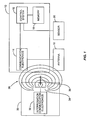
- the RFID chip 10 includes a control system 12 and communication electronics 14.
- the RFID chip 10 may also contain memory 18 for storage of information to be communicated to an interrogation reader 30.
- the RFID chip 10 may store information such as an identification number or other information by using diodes, dip-switches or some other like circuitry in lieu of erasable memory 18.
- An antenna 16 is provided to receive the interrogation signal 36 from the interrogation reader 30.
- the antenna 16 may be either external to or internal to the RFID chip 10. The particular type and location of the antenna 16 will depend on the operating frequency of the RFID chip 10 and the particular design desired.
- the RFID chip 10 may also be connected to sensor 20 for sensing ambient or environmental information surrounding the RFID chip 10, such as pressure or temperature. The data read from the sensor 20 may be stored in memory 18 by the control system 12.
- the senor 20 may be a pressure sensor like that described in U.S. Patent No. 5,675,314 entitled “Tyre pressure sensor,” incorporated herein by reference its entirety.
- Another example of the sensor 20 may be a temperature sensor like that described in U.S. Patent No. 5,731,754 entitled “Transponder and sensor apparatus for sensing and transmitting vehicle tyre parameter data,” incorporated herein by reference its entirety.
- the sensor 20 may be any type of sensor that senses environmental information, including but not limited to pressure, tyre temperature, ambient temperature, humidity, etc.
- the antenna 16 receives the signal 36 through the radiated interrogation field 38.
- the antenna 16 passes the received signals 36 to the communication electronics 14.
- the communication electronics 14 contain circuitry necessary to interpret the signal 36 from the field 38, demodulate the signal 36, and communicate the demodulated signal to the control system 12.
- the control system 12 is an integrated circuit, printed circuit board, or other type of microprocessor or micro-controller electronics that controls the operations of the RFID chip 10.
- the control system 12 is connected to the communication electronics 14 to communicate and receive transmissions.
- the control system 12 is also connected to memory 18 for storing and retrieving information.
- the control system 12 determines if any actions are needed in response to the communications received from the communication electronics 14.
- FIG. 1 also depicts how communication is achieved with the RFID chip 10 using an interrogation reader 30.
- the interrogation reader 30 contains interrogation communication electronics 32 and an interrogation antenna 34.
- the interrogation reader 30 communicates with the RFID chip 10 by emitting an electronic signal 36 modulated in a frequency by interrogating the communication electronics 32 through the interrogation antenna 34.
- the interrogation antenna 34 may be any type of antenna that can radiate the signal 36 through a field 38 so that a compatible device, such as the RFID chip 10, can receive such signal 36 through its own antenna 16.
- the field 38 could be electro-magnetic, magnetic, or electric.
- the signal 36 is a message containing information or a specific request for the RFID chip 10.
- the communication electronics 14 When the antenna 16 is in the presence of the field 38 emitted by the interrogation reader 30, the communication electronics 14 are energized by the signal 36, thereby energizing the RFID chip 10.
- the RFID chip 10 remains energized so long as the antenna 16 is in the field 38 of the interrogation reader 30.
- the communication electronics 14 demodulates the signal 36 and sends the message containing information or request to the control system 12 for appropriate actions.
- the request may be for the RFID chip 10 to communicate its identification, or information about a material or package containing the RFID chip 10, such as date of manufacture, place of manufacture, and/or lot number.
- the message may also be a request for information regarding ambient or environmental measurements sensed by the sensor 20.
- RFID chip 10 is one type of RFID chip.
- Other types of RFID chips 10 may be used with the present invention.
- the RFID chip 10 may have a transmitter that can send information to the interrogation reader 30 without having to alter the signal 36.
- the RFID chip 10 may contain a battery to power the transmitter, or an energy storage unit that is charged by energy received from the signal 36 when the RFID chip 10 is in the range of the field 38. It is readily understood to one of ordinary skill in the art that there are many other types of wireless communications devices and communication techniques than those described herein, and the present invention is not limited to a particular type of device, technique or method.
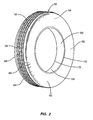
- FIG. 2 illustrates a typical tyre that may be used in the present invention.
- a tyre 50 is comprised of an elongated planar surface 52 that is comprised of a rubber material.
- the elongated planar rubber surface 52 typically contains a tread.
- the elongated planar rubber surface 52 is shaped in the form of a circle to form an inner side 54 and an outer side 56.
- the inner side 54 is the surface on the inside of the circular shape formed by the circular structure of the elongated planar rubber surface 52.
- the outer side 56 is the side of the elongated planar rubber surface 52 that is projected outward from the circular shape.
- the elongated planar rubber surface 52 has two outer edges opposite from each other.
- first outer edge 58 One edge is the first outer edge 58, and the other edge is the second outer edge 60.
- first planar rubber surface 62 and a second planar rubber surface 64 are attached to the elongated planar rubber surface 52.
- the first planar rubber surface 62 connects substantially perpendicular to the first outer edge 58 to form a first inner wall 66.
- the second planar rubber surface 64 also connects substantially perpendicular to the second outer edge 60 to form a second inner wall 68.
- the air is trapped under pressure inside the tyre 50 between the rim and inside of the inner area of the tyre such that the tyre can support a weight, such as a vehicle.
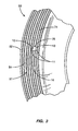
- FIG 3 illustrates an inside portion 51 of the tyre 50.
- the elongated planar rubber surface 52 contains at least one conductive belt 74 inside the rubber to provide structural integrity and support.
- the conductive belt 74 is provided as a plurality of belts 74.
- the RFID chip 10 is placed in the inner side 54 of the tyre 50 in proximity to the belts 74.
- the belts 74 may run in lengths parallel to the tyre, as shown in Figure 3, or the belts 74 may run in diagonal directions.
- the tyre 50 may contain multiple layers of belts 74 where one set of belts 74 in one layer runs in a direction that crosses with the direction of the belts 74 in another layer.
- the RFID chip 10 may be like that described in U.S. Patent No. 6,501,435 entitled “Wireless communication device and method,” which is a continuation-in-part of U.S. Patent 6,483,473 entitled “Wireless communication device and method”.
- An adhesive 76 may be used to adhesively attach the RFID chip 10 to the inner side 54.
- the RFID chip 10 contains several pins, including antenna pins 11 and a ground pin 13. Because of the close proximity of the antenna pins 11, when the RFID chip 10 is attached to the inner side 54 of the tyre 50, the antenna pins 11 are capacitively coupled to the conductive belt 74. This causes the RFID chip 10 to capacitively couple to one or more belts 74 to provide an antenna 16 formed by the belts 74. In this manner, the RFID chip 10, using antenna 16, can wirelessly communicate radio frequency communication signals to the interrogation reader 30.
- the RFID chip 10 may be placed anywhere on the tyre 50 or in proximity to the belts 74 in order for the belts 74 to act as an antenna 16, and exact placement is not important so long as there is capacitive coupling between the pins 11 and the belts 74.
- the conductive belt 74 itself may provide the antenna 16. If only one antenna pin 11 is present on the RFID chip 10, the coupling of the one antenna pin 11 to the conductive belt 74 may provide a monopole antenna 16 arrangement. If two antenna pins 11 are provided, both antenna pins 11 capacitively couple to the gap 78 and/or the conductive belt 74 to provide a dipole antenna 16 arrangement.
- the RFID chip 10 may be further grounded to a ground plane (not shown). The ground plane (not shown) may be provided between the RFID chip 10 and the surface of the tyre 50.
- the conductive belt 74 could be one or more conductive belts 74, and may be comprised from any type of conductive material including but not limited to steel, iron and aluminium.
- the RFID chip 10 may contain one or more antenna pins 11. Using the conductive belt 74 or gaps 78 as an antenna 16, the RFID chip 10 may operate at different operating frequencies according to the length and design of the conductive belts. For instance, the conductive belts may be capacitively coupled to the RFID chip 10 so that the RFID chip 10 has an operating frequency of 13.56 MHz, 915 MHz, or 2.45 GHz, for example.
- the RFID chip 10 may be coupled to the first inner wall 66 or second inner wall 68 of the tyre 50 if either the first inner wall 66 (not shown in Fig. 3) or second inner wall 68 (not shown in Fig. 3) contains at least one conductive belt 74.
- the RFID Chip 10 may be placed in a position on the first inner wall 66 or second inner wall 68 such that the antenna pin 11 of the RFID chip 10 is close enough to the conductive belt 74 in the elongated planar rubber surface 52 of the tyre 50 to establish a capacitive coupling.
- the RFID chip 10 in different regions of the elongated planar rubber surface 52 on the first inner wall 66 or second inner wall 68 may affect the performance and operating frequency of the antenna 16 that is formed by capacitively coupling the antenna pin 11 to the RFID chip 10. Empirical testing may be required to fine-tune the performance of the antenna 16 to the desired application.
- the antenna pins 11 may also be one or more conductive tabs, as described in previously referenced U.S. Patent No. 6,501,435 and 6,483,473.
- FIG 4 illustrates an alternative embodiment of the present invention.
- a plurality of conductive belts 74 form a gap 78, as illustrated in Figure 4.
- the gap 78 may act as a bounded slot 78.
- the slot 78 in Figure 4 is shown in solid outline, the slot 78 is embedded within the elongated planar rubber surface 52.
- the antenna pin 11 of the RFID Chip 10 may capacitively couple to the slot 78 to form a slot antenna 16.
- the RFID chip 10 can wirelessly communicate with interrogation reader 30 or other reception device using the capacitive coupling to the slot 78 to form a slot antenna 16. More information on slot antennas 16 can be found in U.S. Patent No. 6,628,273 entitled "Remote communication using slot antenna,” incorporated herein by reference in its entirety.
- the conductive belts 74 can be considered as a series of parallel capacitors coupled conductively to each other.
- the slot 78 is self-terminating due to the cross-capacitance between the multiple conductive belts 74 in proximity to each other.
- an electric field must be established at a point along the length of the slot 78 between two conductive belts 74 through the coupling of the RFID chip 10 to the belts 74.
- the elongated rubber planar surface 52 that separates the RFID chip 10 and/or pin 11 from the slot 78 causes the RFID chip 10 or pin 11 to conductively couple insufficiently to the slot 78
- a number of methods may be used to improve the performance of the coupling by varying the shape of the RFID chip 10 and/or adding additional conductive components of varying geometries to the pin 11 that is used to couple the pin 11 to the slot 78.
- conductive tabs like those described in previously referenced U.S. Patent No. 6,501,435 may be coupled to the pin 11 or pins 11 of the RFID chip 10, and the conductive tabs are then coupled to the belts 74 to provide the antenna 16.
- the RFID chip 10 may capacitively couple to the slot 78 using one antenna pin 11 or multiple antenna pins 11.
- the slot antenna 16 radiation pattern may be similar to a monopole type antenna or similar to a dipole type antenna, depending on the particular configuration. Further, the RFID chip 10 may be grounded to a ground plane.
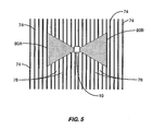
- Figure 5 illustrates one embodiment of the present invention where additional conductive components are coupled to the pins 11 of the RFID chip 10, and these conductive components are coupled to the belts 74.
- Two conductive components 80A, 80B are coupled to the RFID chip 10 and/or pins 11 in the form of a bow tie.
- the wider area of the conductive components 80A, 80B, away from the slot 78 position that is closest to the RFID chip 10, tends to couple to the belts 74 together at RF frequencies, making it easier for the RF current created by receipt of signal 36 to flow around a virtual slot.
- the virtual slot is formed by the plurality of slots between the sections of the belt 74.
- the two conductive components 80A, 80B forming a bow tie strongly coupling the belts 74 further away from the RFID chip 10 and providing weaker coupling between the belts 74 toward the RFID chip 10.
- the narrower area of the conductive components 80A, 80B, as they get closer to the RFID chip 10, tend to increase the impedance and therefore the electric field component of a flow current, thereby acting as an impedance matching section to the RFID chip 10.
- Various other conductive components 80 having various shapes can also be used that include a greater surface area farther from the RFID chip 10 and whose surface area decreases closer to the RFID chip 10, and the present invention is not limited to any particular structure for the conductive components 80.
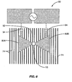
- FIG. 6 An alternative embodiment of that illustrated in Figure 5 is illustrated in Figure 6.
- the same UHF structure illustrated in Figure 5 is also used in this embodiment.
- this same structure can also be used for the RFID chip 10 to operate as a low frequency tag by coupling to an electric field created by an electric field reader 90.
- the electric field reader 90 generates a high differential AC voltage across a slot 92 capacitively coupling the RFID chip 10 to the electric field.
- the electric field is generated in a direction parallel to the alignment of the belts 74 so as to not cause a shorting of the flux lines in the electric field that would prevent operation.
- the capacitors 94 contained in Figure 6 are not actually present, but are representations of the capacitive coupling between the electric field reader 90 and the RFID chip 10 and its conductive components 80A, 80B.
- the belts 74 inline with the slot 92 do not interact significantly with the electric field generated by the electric field reader 90, except that the belts 74 become charged by the voltage placed on the belts 74 via the capacitive coupling with the electric field reader 90.
- FIG 7 illustrates another embodiment of the present invention wherein the RFID chip 10 is configured to operate at two different operating frequencies. Impedance matching between the elongated planar rubber surface 52 and belts 74 to the RFID chip 10 can be considered to provide operation at dual frequencies.
- the RFID chip 10 is mounted on the inner side 54 of the tyre 50, as previously described. However, the RFID chip 10 is designed so that the RFID chip 10 is impedance matched to the tyre 50 and belts 74 at two different operating frequencies, thereby allowing the RFID chip 10 to respond to signals 36 having two different operating frequencies.
- Conductive components 80A, 80B are coupled to the RFID chip 10 and/or pins 11. The conductive components 80A, 80B are arranged asymmetrically to each other, as defined in previously referenced U.S. Patent No. 6,501,435 above.
- the RFID chip 10 and its conductive components 80A, 80B are configured to form an asymmetric dipole antenna 16.
- the conductive components 80A, 80B are tuned to treat the belts 74 as effectively continuous conductors to form a dipole antenna at such first operating frequency, wherein the belts 74 radiate upwards towards the wheel (not shown) of the tyre 50.
- the conductive components 80A, 80B may be designed to operate at an operating frequency of 2.45 GHz.
- the RFID chip 10 and its conductive components 80A, 80B act as an insert coupling to the gap 78 between the belts 74, wherein the gap 78 provides a slot 78 to act as a slot antenna 16.
- the conductive components 80A, 80B and the belts 78 may be configured to couple to the slot 78 to form a slot antenna 16 when a signal 36 having an operating frequency of 915 MHz is received.
- the nature of the slot 78 formed by the parallel coupled belts 74, wherein the half wave slot 78 length is terminated by cross-capacitance can be made to be very broadband by choice of appropriate impedance matching components.
- the impedance matching components may be similar to those described in co-pending patent application Serial No. 10/125783, entitled “Multiple feed point slot antenna,” filed on April 18, 2002, and incorporated herein by reference in its entirety.
- the slot 78 has a number of different lengths at which it self-terminates. Therefore, the RFID chip 10 may be configured to couple to the slots 78 at different operating frequencies to form different slot antennas 16 yielding more than two effective operating frequencies for the RFID chip 10.
- the RFID chip 10 could be configured to operate at 869 MHz and 915 MHz using the various slot 78 lengths as different slot antennas 16, and 2.45 GHz using the conductive components 80A, 80B as a dipole antenna 16.
- the present invention can be used with a single conductive component 80 to form a monopole antenna.
- FIG 8 illustrates another embodiment of the present invention wherein the RFID chip 10 uses the tyre 50 structure to form a slot antenna 16.
- the RFID chip 10 is coupled to two tyre 50 conductive structures - the belt 74 and the bead 82.
- the bead 82 is a series of loops of wire designed to reinforce the tyre edge in the area where it is mounted onto a wheel.
- the structure of the tyre 50 is in the form of an annular slot 84, which is formed by the space between the belts 74 and the bead 82.
- a conductive component 80 may be coupled to the RFID chip 10 in order to couple to the slot 84 to form a slot antenna 16.
- the form of the slot 84 will dictate its operating frequency. At comparatively low operating frequencies, the slot 84 will act as a full wave or half wave antenna. At higher operating frequencies, the conductive component 80 can stimulate a harmonic mode of the slot 84.
- the slot 84 can form a transmission line 86 that leaks into the environment surrounding the tyre 50 to form an antenna 16. If the RFID chip 10 needs to be interrogated by an interrogation reader 30 or other transmission device on a vehicle, the signal 36 can be radiated into this transmission line 86 at any point around the tyre 50, and the transmission line 86 propagates the signal 36 around the slot 84. Even though the tyre 50 containing the RFID chip 10 is rotating, making it come in and out of the field 38 of the interrogation reader 30, the signal's 36 radiation into the transmission line 86 allows continuous communication between the interrogation reader 30 and the RFID chip 10.
- the present invention is not limited to any particular type of RFID chip 10, its components, the interrogation reader 30, the tyre 50, and its components.
- couple, coupled, or coupling is defined as either directly connecting or reactive coupling.
- Reactive coupling is defined as either capacitive or inductive coupling.
Landscapes
- Engineering & Computer Science (AREA)
- Computer Hardware Design (AREA)
- Microelectronics & Electronic Packaging (AREA)
- Physics & Mathematics (AREA)
- General Physics & Mathematics (AREA)
- Theoretical Computer Science (AREA)
- Remote Sensing (AREA)
- Arrangements For Transmission Of Measured Signals (AREA)
- Support Of Aerials (AREA)
- Details Of Aerials (AREA)
- Heating, Cooling, Or Curing Plastics Or The Like In General (AREA)
Claims (30)
- Système pour communiquer des informations sans fil à l'aide d'un pneumatique (50), comprenant : un pneumatique (50), comprenant :une surface (52) de caoutchouc planaire allongée possédant un côté intérieur (54) et un côté extérieur (56) formant une forme circulaire, dans lequel ladite surface (52) de caoutchouc comprend un premier bord extérieur (58) et un deuxième bord extérieur (60) opposé audit premier bord extérieur (58) ;un premier côté (62) de caoutchouc planaire relié de manière sensiblement perpendiculaire audit premier bord extérieur (58) pour former une première paroi intérieure (66) ; etun deuxième côté (64) de caoutchouc planaire relié de manière sensiblement perpendiculaire audit deuxième bord extérieur (60) pour former une deuxième paroi intérieure (68) ; dans lequelladite surface (52) de caoutchouc planaire allongée, ledit premier côté (62) de caoutchouc planaire ou ledit deuxième côté (64) de caoutchouc planaire sont incorporés dans au moins une ceinture conductrice (74) pour améliorer l'intégrité structurelle dudit pneumatique (50) ; etune puce (10) d'identification par radiofréquence,
caractérisé en ce quela puce (10) d'identification par radiofréquence présente au moins une tige (11) d'antenne, dans lequel ladite puce (10) d'identification par radiofréquence est fixée audit côté intérieur (54), à ladite première paroi intérieure (66) ou à ladite deuxième paroi intérieure (68) dudit pneumatique (50) et dans lequel ladite surface (52) de caoutchouc planaire, ledit premier côté (62) de caoutchouc planaire ou ledit deuxième côté (64) de caoutchouc planaire forme un diélectrique entre ladite au moins une ceinture conductrice (74) et ladite puce (10) d'identification par radiofréquence ; et en ce que l'ensemble desdites tiges (11) d'antenne sont couplées de manière capacitive à ladite au moins une ceinture conductrice (74) pour former une antenne (16) pour la communication par signaux radioélectriques vers et en provenance de ladite puce (10) d'identification par radiofréquence concernant ledit pneumatique (50). - Système selon la revendication 1, dans lequel ladite au moins une ceinture conductrice (74) comprend une pluralité de ceintures conductrices (74).
- Système selon la revendication 1, dans lequel ladite au moins une ceinture conductrice (74) est constituée d'un matériau compris dans le groupe constitué de l'acier, du fer, et de l'aluminium.
- Système selon la revendication 1, dans lequel ladite au moins une tige (11) d'antenne est une tige d'antenne étant couplée de manière capacitive à ladite au moins une ceinture conductrice (74) pour former une antenne unipolaire.
- Système selon la revendication 4; dans lequel ladite puce (10) d'identification par radiofréquence comprend en outre une tige (13) de masse couplée à un retour de masse pour fournir une masse pour ladite puce (10) d'identification par radiofréquence.
- Système selon la revendication 2, dans lequel au moins une tige d'antenne est composée de deux tiges (11) d'antenne étant couplées de manière capacitive à ladite pluralité de ceintures conductrices (74) pour former une antenne dipôle.
- Système selon la revendication 2, dans lequel ladite pluralité de ceintures conductrices (74) forme une pluralité de fentes (78, 92) dans lesquelles ladite au moins une tige (11) d'antenne est couplée de manière capacitive à ladite fente pour former une antenne à fentes (78, 92).
- Système selon la revendication 1, dans lequel ladite antenne (16) fonctionne à une fréquence de fonctionnement comprise dans le groupe constitué d'ondes décimétriques et d'ondes métriques.
- Système selon la revendication 1, dans lequel ladite puce (10) d'identification par radiofréquence fonctionne à une fréquence de fonctionnement à partir du groupe constitué de 2,45 GHz, 869 MHz, 915 MHz, et 13,56 MHz.
- Système selon la revendication 1, comprenant en outre un adhésif non-conducteur disposé entre ladite puce (10) d'identification par radiofréquence et ladite surface intérieure (54) pour coupler de manière adhésive ladite puce (10) d'identification par radiofréquence à ladite surface intérieure (54).
- Système selon la revendication 1, dans lequel ladite puce (10) d'identification par radiofréquence communique sans fil des informations concernant ledit pneumatique (50), à l'aide de ladite antenne (16), à un lecteur (30) d'interrogation.
- Système selon la revendication 11, dans lequel lesdites informations concernant ledit pneumatique (50) sont comprises dans le groupe constitué de la pression dudit pneumatique (50), de la température dudit pneumatique (50), de la pression ambiante autour dudit pneumatique (50), et de la température ambiante autour dudit pneumatique (50).
- Système selon la revendication 7, comprenant en outre au moins un composant conducteur (80, 80A, 80B) couplé à ladite tige (11) d'antenne et couplé à ladite fente (78, 92) pour former ladite antenne.
- Système selon la revendication 13, dans lequel ledit au moins un composant conducteur (80) est composé de deux composants conducteurs (80A, 80B) formés sous forme d'un noeud papillon.
- Système selon la revendication 13, comprenant en outre un lecteur (90) de champ électrique qui génère un champ électrique à travers ladite fente (92) pour coupler de manière capacitive ledit champ électrique audit au moins un composant conducteur (80, 80A, 80B).
- Système selon la revendication 13, comprenant en outre un lecteur (30) d'interrogation qui émet un signal électronique, et dans lequel ledit au moins un composant conducteur est constitué d'au moins deux composants conducteurs (80A, 80B), et dans lequel un desdits au moins deux composants conducteurs est de forme asymétrique par rapport au deuxième (80A, 80B) desdits au moins deux composants conducteurs, et dans lequel lesdits au moins composants conducteurs (80A, 80B) fonctionnent en tant qu'antenne dipôle au moment de recevoir ledit signal électronique présentant une première fréquence, et dans lequel lesdits au moins deux composants conducteurs (80A, 80B) s'accouplent à ladite fente (94) pour former une antenne à fentes au moment de recevoir ledit signal électronique présentant une deuxième fréquence différente de ladite première fréquence.
- Système selon la revendication 16, dans lequel ladite fente (94) contient une pluralité de longueurs à terminaison automatique, dans lequel lesdits au moins deux composants conducteurs (80A, 80B) s'accouplent à ladite fente (92) présentant une première longueur pour former une antenne à fentes au moment de recevoir ledit signal électronique présentant ladite deuxième fréquence, et lesdits au moins deux composants conducteurs (80A, 80B) s'accouplent à ladite fente (92) présentant une deuxième longueur pour former une antenne à fentes au moment de recevoir ledit signal électronique présentant une troisième fréquence différente desdites première et deuxième fréquences.
- Système selon la revendication 13, dans lequel ledit au moins un composant conducteur (80) est composé de deux composants conducteurs (80A, 80B) qui s'accouplent à au moins une ceinture (74) de ladite pluralité de ceintures conductrices (74) et à un talon (82) sur ledit pneumatique pour former une antenne (16) à fentes, et dans lequel un espace situé entre ladite au moins une ceinture (74) et ledit talon (82) forme une chaîne cinématique (86) pour recevoir un signal émis par un lecteur (30) d'interrogation en direction de ladite antenne (16) à fentes.
- Procédé consistant à communiquer sans fil des informations concernant un pneumatique (50), comprenant les étapes consistant à : fixer une puce (10) d'identification par radiofréquence à l'intérieur d'un pneumatique (50) en caoutchouc, caractérisé en ce que
la puce (10) d'identification par radiofréquence présente au moins une tige (11) d'antenne et le procédé comprend en outre le couplage de manière capacitive de l'ensemble desdites tiges (11) d'antenne à au moins une ceinture conductrice (74) contenue à l'intérieur dudit pneumatique (50) en caoutchouc pour former une antenne (16) pour des communications par signaux radioélectriques ; et la réception d'un signal radioélectrique reçu par l'intermédiaire de ladite antenne (16). - Procédé selon la revendication 19, comprenant en outre l'étape consistant à rétro-diffuser ledit signal radioélectrique reçu par l'intermédiaire de ladite antenne (16).
- Procédé selon la revendication 19, comprenant en outre l'étape consistant à transmettre un signal radioélectrique séparé par l'intermédiaire de ladite antenne (16).
- Procédé selon la revendication 19, dans lequel ladite au moins une ceinture conductrice (74) est composée d'une pluralité de ceintures conductrices (74).
- Procédé selon la revendication 22, dans lequel ladite étape consistant à coupler de manière capacitive comprend en outre le couplage de manière capacitive de ladite au moins une tige (11) d'antenne à une fente (78, 92) formée par lesdites ceintures conductrices (74) pour former une antenne (16) à fentes.
- Procédé selon la revendication 19, comprenant en outre l'étape consistant à mettre à la masse ladite puce (10) d'identification par radiofréquence.
- Procédé selon la revendication 22, dans lequel ladite au moins une tige d'antenne est composée de deux tiges (11) d'antenne et dans lequel ladite étape consistant à coupler de manière capacitive comprend en outre le couplage de manière capacitive desdites deux tiges (11) d'antenne à ladite pluralité de ceintures conductrices (74) pour former une antenne dipôle pour des communications par signaux radioélectriques.
- Procédé selon la revendication 19, comprenant en outre :la fixation d'au moins un composant conducteur (80) à ladite tige (11) d'antenne, dans lequel ladite au moins une ceinture conductrice est composée d'une pluralité de ceintures conductrices (74) présentant une fente (78, 92) formée entre ladite pluralité de ceintures conductrices (74) ;
etdans laquelle ladite étape consistant à coupler de manière capacitive comprend en outre le couplage de manière capacitive dudit au moins un composant conducteur (80) à ladite fente (78, 92) pour former ladite antenne (16). - Procédé selon la revendication 26, comprenant en outre la génération d'un champ électrique à travers ladite fente (92) pour coupler de manière capacitive ledit champ électrique audit au moins un composant conducteur (80).
- Procédé selon la revendication 26, dans lequel ledit au moins un composant conducteur (80) comprend deux composants conducteurs (80A, 80B), et comprend en outre: la réception d'un signal présentant une première fréquence de fonctionnement à l'aide de ladite antenne (16) à fentes, et l'émission d'un signal électronique ; etla réception d'un signal présentant une deuxième fréquence de fonctionnement utilisant lesdits deux composants conducteurs (80A, 80B) en tant qu'antenne dipôle.
- Procédé selon la revendication 28, comprenant en outre la disposition desdits deux composants conducteurs (80A, 80B) de manière asymétrique l'un par rapport à l'autre.
- Procédé selon la revendication 19, dans lequel ledit au moins un composant conducteur (80) comprend deux composants conducteurs (80A, 80B), et comprend en outre : la fixation desdits deux composants conducteurs (80A, 80B) entre ladite au moins une ceinture conductrice (74) et un talon (82) sur ledit pneumatique (50) formant une fente (92) pour former une antenne à fentes ; et la réception d'un signal électronique envoyé par un lecteur (30) d'interrogation qui est émis par l'intermédiaire de ladite fente (92) formée entre ladite au moins une ceinture conductrice (74) et ledit talon (82).
Applications Claiming Priority (3)
| Application Number | Priority Date | Filing Date | Title |
|---|---|---|---|
| US10/223,065 US7050017B2 (en) | 2002-08-14 | 2002-08-14 | RFID tire belt antenna system and method |
| US223065 | 2002-08-14 | ||
| PCT/IB2003/003589 WO2004016454A1 (fr) | 2002-08-14 | 2003-08-07 | Procede et systeme d'antenne a bande pour pneumatique a identification par radiofrequence |
Publications (2)
| Publication Number | Publication Date |
|---|---|
| EP1539509A1 EP1539509A1 (fr) | 2005-06-15 |
| EP1539509B1 true EP1539509B1 (fr) | 2007-01-03 |
Family
ID=31886638
Family Applications (1)
| Application Number | Title | Priority Date | Filing Date |
|---|---|---|---|
| EP03787966A Expired - Lifetime EP1539509B1 (fr) | 2002-08-14 | 2003-08-07 | Procede et systeme d'antenne a bande pour pneumatique a identification par radiofrequence |
Country Status (9)
| Country | Link |
|---|---|
| US (1) | US7050017B2 (fr) |
| EP (1) | EP1539509B1 (fr) |
| JP (1) | JP4425137B2 (fr) |
| CN (1) | CN100408360C (fr) |
| AT (1) | ATE350229T1 (fr) |
| AU (1) | AU2003250492A1 (fr) |
| DE (1) | DE60310957T2 (fr) |
| LT (1) | LT5312B (fr) |
| WO (1) | WO2004016454A1 (fr) |
Families Citing this family (142)
| Publication number | Priority date | Publication date | Assignee | Title |
|---|---|---|---|---|
| US7190319B2 (en) * | 2001-10-29 | 2007-03-13 | Forster Ian J | Wave antenna wireless communication device and method |
| WO2003038747A2 (fr) * | 2001-10-29 | 2003-05-08 | Marconi Intellectual Property (Us) Inc | Dispositif de radiocommunications a antenne beverage, et procede correspondant |
| US6630910B2 (en) * | 2001-10-29 | 2003-10-07 | Marconi Communications Inc. | Wave antenna wireless communication device and method |
| US7009576B2 (en) * | 2002-06-11 | 2006-03-07 | Michelin Recherche Et Technique S.A. | Radio frequency antenna for a tire and method for same |
| US20040134578A1 (en) | 2002-12-23 | 2004-07-15 | Kleckner James P. | Tire with tire tag |
| ATE530998T1 (de) | 2003-07-07 | 2011-11-15 | Avery Dennison Corp | Rfid-einrichtung mit änderbaren charakteristika |
| US8315567B2 (en) * | 2003-09-26 | 2012-11-20 | Agere Systems Inc. | Method and system for wireless communication with an integrated circuit under evaluation |
| WO2005045781A1 (fr) * | 2003-11-07 | 2005-05-19 | Kabushiki Kaisha Bridgestone | Dispositif de capteur de pneu et methode de transmission d'informations concernant les pneus |
| DE102004004292A1 (de) * | 2004-01-28 | 2005-09-08 | Siemens Ag | Anordnung und Verfahren zum bidirektionalen Übertragen von Signalen bei einem Kraftfahrzeug |
| DE102004008929A1 (de) * | 2004-02-24 | 2005-09-01 | Bayerische Motoren Werke Ag | Fahrzeugreifen mit Stahlgürteldrähten sowie einer im Bereich der Lauffläche angeordneten Dipol-Antenne |
| KR100603761B1 (ko) * | 2004-04-22 | 2006-07-24 | 삼성전자주식회사 | 마이크로웨이브 트랜스폰더 |
| KR101091895B1 (ko) * | 2004-08-21 | 2011-12-08 | 삼성테크윈 주식회사 | 타이어 장착용 rfid 태그 |
| JP2006235824A (ja) * | 2005-02-23 | 2006-09-07 | Omron Corp | 広帯域icタグ |
| JP2006295729A (ja) * | 2005-04-13 | 2006-10-26 | Fujitsu Ltd | Rfidタグおよびアンテナ配置方法 |
| JP2009520643A (ja) * | 2005-12-15 | 2009-05-28 | ザ・グッドイヤー・タイヤ・アンド・ラバー・カンパニー | 車両特性を決定する方法 |
| US7604029B2 (en) * | 2005-12-15 | 2009-10-20 | Michelin Recherche Et Technique S.A. | Wear indicating tire |
| US7154283B1 (en) | 2006-02-22 | 2006-12-26 | Avery Dennison Corporation | Method of determining performance of RFID devices |
| JP5203357B2 (ja) * | 2006-05-26 | 2013-06-05 | ジーイー・ヘルスケア・バイオサイエンス・コーポレイション | 容器中のパラメータを監視するシステム及び方法 |
| JP2008011385A (ja) * | 2006-06-30 | 2008-01-17 | Alps Electric Co Ltd | アンテナ装置 |
| US7659857B2 (en) * | 2006-07-05 | 2010-02-09 | King Patrick F | System and method for providing a low and narrow-profile radio frequency identification (RFID) tag |
| US20080084285A1 (en) * | 2006-10-05 | 2008-04-10 | Kulvir Singh Bhogal | System and method for autonomic detection of tire tread wear |
| US8873585B2 (en) | 2006-12-19 | 2014-10-28 | Corning Optical Communications Wireless Ltd | Distributed antenna system for MIMO technologies |
| US7812731B2 (en) | 2006-12-22 | 2010-10-12 | Vigilan, Incorporated | Sensors and systems for detecting environmental conditions or changes |
| US8502684B2 (en) | 2006-12-22 | 2013-08-06 | Geoffrey J. Bunza | Sensors and systems for detecting environmental conditions or changes |
| JP2008195189A (ja) * | 2007-02-13 | 2008-08-28 | Mitomo Shoji Kk | タイヤ |
| US9276656B2 (en) * | 2007-02-19 | 2016-03-01 | Corning Optical Communications Wireless Ltd | Method and system for improving uplink performance |
| US20100054746A1 (en) | 2007-07-24 | 2010-03-04 | Eric Raymond Logan | Multi-port accumulator for radio-over-fiber (RoF) wireless picocellular systems |
| ITTO20070563A1 (it) * | 2007-07-30 | 2009-01-31 | St Microelectronics Srl | Dispositivo di identificazione a radiofrequenza con antenna accoppiata in near field |
| US7902815B2 (en) | 2007-09-18 | 2011-03-08 | The United States Of America As Represented By The Administrator Of The National Aeronautics And Space Administration | Wireless system and method for collecting motion and non-motion related data of a rotating system |
| US8175459B2 (en) | 2007-10-12 | 2012-05-08 | Corning Cable Systems Llc | Hybrid wireless/wired RoF transponder and hybrid RoF communication system using same |
| WO2009053910A2 (fr) | 2007-10-22 | 2009-04-30 | Mobileaccess Networks Ltd. | Système de communication utilisant des fils à faible bande passante |
| FR2922487B1 (fr) | 2007-10-23 | 2009-12-11 | Michelin Soc Tech | Organe formant support pour un dispositif et pneumatique comprenant un tel organe |
| FR2922486B1 (fr) | 2007-10-23 | 2009-12-11 | Michelin Soc Tech | Ensemble d'un pneumatique et d'un organe souple |
| US8175649B2 (en) | 2008-06-20 | 2012-05-08 | Corning Mobileaccess Ltd | Method and system for real time control of an active antenna over a distributed antenna system |
| WO2009081376A2 (fr) | 2007-12-20 | 2009-07-02 | Mobileaccess Networks Ltd. | Extension de services et d'applications d'extérieur à des zones fermées |
| CN104077622B (zh) * | 2008-05-26 | 2016-07-06 | 株式会社村田制作所 | 无线ic器件系统及无线ic器件的真伪判定方法 |
| US8179203B2 (en) | 2008-10-09 | 2012-05-15 | The United States Of America, As Represented By The Administrator Of The National Aeronautics And Space Administration | Wireless electrical device using open-circuit elements having no electrical connections |
| US8157172B2 (en) * | 2008-10-30 | 2012-04-17 | The Goodyear Tire & Rubber Company | RFID tag package and tire assembly |
| US20100123584A1 (en) * | 2008-11-18 | 2010-05-20 | Robert Edward Lionetti | Method of embedding an electronic device in a tire |
| AU2010210766A1 (en) | 2009-02-03 | 2011-09-15 | Corning Cable Systems Llc | Optical fiber-based distributed antenna systems, components, and related methods for monitoring and configuring thereof |
| US9673904B2 (en) | 2009-02-03 | 2017-06-06 | Corning Optical Communications LLC | Optical fiber-based distributed antenna systems, components, and related methods for calibration thereof |
| EP2394379B1 (fr) | 2009-02-03 | 2016-12-28 | Corning Optical Communications LLC | Systèmes et composants d'antennes distribuées à base de fibres optiques, et procédés de calibrage associés |
| WO2010089719A1 (fr) | 2009-02-08 | 2010-08-12 | Mobileaccess Networks Ltd. | Système de communication utilisant des câbles transportant des signaux ethernet |
| US8231060B2 (en) * | 2009-07-02 | 2012-07-31 | Cooper Tire & Rubber Company | Tire antenna for RFID |
| US9590733B2 (en) | 2009-07-24 | 2017-03-07 | Corning Optical Communications LLC | Location tracking using fiber optic array cables and related systems and methods |
| US8548330B2 (en) | 2009-07-31 | 2013-10-01 | Corning Cable Systems Llc | Sectorization in distributed antenna systems, and related components and methods |
| US8280259B2 (en) | 2009-11-13 | 2012-10-02 | Corning Cable Systems Llc | Radio-over-fiber (RoF) system for protocol-independent wired and/or wireless communication |
| US9385420B2 (en) * | 2010-02-12 | 2016-07-05 | Cooper Tire & Rubber Company | Wireless antenna for RFID tires |
| WO2011099958A1 (fr) * | 2010-02-12 | 2011-08-18 | Cooper Tire & Rubber Company | Antenne sans fil pour rfid pour pneus |
| US8275265B2 (en) | 2010-02-15 | 2012-09-25 | Corning Cable Systems Llc | Dynamic cell bonding (DCB) for radio-over-fiber (RoF)-based networks and communication systems and related methods |
| FR2956616A1 (fr) * | 2010-02-23 | 2011-08-26 | Michelin Soc Tech | Pneumatique comprenant un organe electronique |
| WO2011123336A1 (fr) | 2010-03-31 | 2011-10-06 | Corning Cable Systems Llc | Services de localisation dans des composants et systèmes de communications distribués à base de fibres optiques et procédés connexes |
| US9122967B2 (en) | 2010-04-14 | 2015-09-01 | Technologies Roi, Llc | Radio frequency identification tags and methods employing ceramic components, which may be suitable for use in extreme environmental conditions |
| US20110259501A1 (en) * | 2010-04-26 | 2011-10-27 | Mahmoud Cherif Assaad | Hybrid cord in a belt ply for a pneumatic tire |
| US9525488B2 (en) | 2010-05-02 | 2016-12-20 | Corning Optical Communications LLC | Digital data services and/or power distribution in optical fiber-based distributed communications systems providing digital data and radio frequency (RF) communications services, and related components and methods |
| US20110268446A1 (en) | 2010-05-02 | 2011-11-03 | Cune William P | Providing digital data services in optical fiber-based distributed radio frequency (rf) communications systems, and related components and methods |
| US8570914B2 (en) | 2010-08-09 | 2013-10-29 | Corning Cable Systems Llc | Apparatuses, systems, and methods for determining location of a mobile device(s) in a distributed antenna system(s) |
| EP2606707A1 (fr) | 2010-08-16 | 2013-06-26 | Corning Cable Systems LLC | Grappes d'antennes distantes, et systèmes, composants et procédés associés adaptés pour prendre en charge une propagation de signaux de données numériques entre des unités d'antennes distantes |
| US9160449B2 (en) | 2010-10-13 | 2015-10-13 | Ccs Technology, Inc. | Local power management for remote antenna units in distributed antenna systems |
| US9252874B2 (en) | 2010-10-13 | 2016-02-02 | Ccs Technology, Inc | Power management for remote antenna units in distributed antenna systems |
| US11296504B2 (en) | 2010-11-24 | 2022-04-05 | Corning Optical Communications LLC | Power distribution module(s) capable of hot connection and/or disconnection for wireless communication systems, and related power units, components, and methods |
| EP2643947B1 (fr) | 2010-11-24 | 2018-09-19 | Corning Optical Communications LLC | Module(s) de distribution d'énergie électrique capable(s) d'une connexion et/ou déconnexion à chaud pour des systèmes d'antennes réparties, et unités d'énergie électrique, composants et procédés associés |
| CN203504582U (zh) | 2011-02-21 | 2014-03-26 | 康宁光缆系统有限责任公司 | 一种分布式天线系统及用于在其中分配电力的电源装置 |
| CN103548290B (zh) | 2011-04-29 | 2016-08-31 | 康宁光缆系统有限责任公司 | 判定分布式天线系统中的通信传播延迟及相关组件、系统与方法 |
| WO2012148940A1 (fr) | 2011-04-29 | 2012-11-01 | Corning Cable Systems Llc | Systèmes, procédés et dispositifs pour augmenter la puissance radiofréquence (rf) dans systèmes d'antennes distribuées |
| US8596117B2 (en) | 2011-10-03 | 2013-12-03 | Bridgestone Americas Tire Operations, Llc | Attachment patch for mounting various devices |
| JP2013126838A (ja) * | 2011-12-19 | 2013-06-27 | Toppan Forms Co Ltd | タイヤ |
| WO2013142662A2 (fr) | 2012-03-23 | 2013-09-26 | Corning Mobile Access Ltd. | Puce(s) de circuit intégré à radiofréquence (rfic) servant à fournir des fonctionnalités de système d'antenne à répartition, et composants, systèmes, et procédés connexes |
| WO2013148986A1 (fr) | 2012-03-30 | 2013-10-03 | Corning Cable Systems Llc | Réduction d'un brouillage lié à la position dans des systèmes d'antennes distribuées fonctionnant selon une configuration à entrées multiples et à sorties multiples (mimo), et composants, systèmes et procédés associés |
| US9781553B2 (en) | 2012-04-24 | 2017-10-03 | Corning Optical Communications LLC | Location based services in a distributed communication system, and related components and methods |
| EP2842245A1 (fr) | 2012-04-25 | 2015-03-04 | Corning Optical Communications LLC | Architectures de système d'antenne distribué |
| WO2013181247A1 (fr) | 2012-05-29 | 2013-12-05 | Corning Cable Systems Llc | Localisation au moyen d'ultrasons de dispositifs clients à complément de navigation par inertie dans des systèmes de communication distribués et dispositifs et procédés associés |
| US9154222B2 (en) | 2012-07-31 | 2015-10-06 | Corning Optical Communications LLC | Cooling system control in distributed antenna systems |
| WO2014024192A1 (fr) | 2012-08-07 | 2014-02-13 | Corning Mobile Access Ltd. | Distribution de services de gestion multiplexés par répartition dans le temps (tdm) dans un système d'antennes distribuées, et composants, systèmes et procédés associés |
| US9455784B2 (en) | 2012-10-31 | 2016-09-27 | Corning Optical Communications Wireless Ltd | Deployable wireless infrastructures and methods of deploying wireless infrastructures |
| KR102255579B1 (ko) | 2012-11-13 | 2021-05-25 | 쿠퍼 타이어 앤드 러버 캄파니 | 고무, 엘라스토머 또는 중합체 안테나를 갖는 무선 주파수 식별 장치 태그를 갖는 타이어와 같은 제품 |
| US10257056B2 (en) | 2012-11-28 | 2019-04-09 | Corning Optical Communications LLC | Power management for distributed communication systems, and related components, systems, and methods |
| CN105308876B (zh) | 2012-11-29 | 2018-06-22 | 康宁光电通信有限责任公司 | 分布式天线系统中的远程单元天线结合 |
| US9647758B2 (en) | 2012-11-30 | 2017-05-09 | Corning Optical Communications Wireless Ltd | Cabling connectivity monitoring and verification |
| US9158864B2 (en) | 2012-12-21 | 2015-10-13 | Corning Optical Communications Wireless Ltd | Systems, methods, and devices for documenting a location of installed equipment |
| US9329153B2 (en) | 2013-01-02 | 2016-05-03 | United States Of America As Represented By The Administrator Of The National Aeronautics And Space Administration | Method of mapping anomalies in homogenous material |
| US9497706B2 (en) | 2013-02-20 | 2016-11-15 | Corning Optical Communications Wireless Ltd | Power management in distributed antenna systems (DASs), and related components, systems, and methods |
| WO2014199384A1 (fr) | 2013-06-12 | 2014-12-18 | Corning Optical Communications Wireless, Ltd. | Coupleur directif optique a commande en tension |
| EP3008828B1 (fr) | 2013-06-12 | 2017-08-09 | Corning Optical Communications Wireless Ltd. | Duplexage par répartition temporelle (tdd) dans des systèmes de communication répartis, comprenant des systèmes d'antenne répartis (das) |
| US9247543B2 (en) | 2013-07-23 | 2016-01-26 | Corning Optical Communications Wireless Ltd | Monitoring non-supported wireless spectrum within coverage areas of distributed antenna systems (DASs) |
| US9661781B2 (en) | 2013-07-31 | 2017-05-23 | Corning Optical Communications Wireless Ltd | Remote units for distributed communication systems and related installation methods and apparatuses |
| EP3039814B1 (fr) | 2013-08-28 | 2018-02-21 | Corning Optical Communications Wireless Ltd. | Gestion de énergie pour des systèmes de communication distribués, et composants, systèmes et procédés associés |
| US9385810B2 (en) | 2013-09-30 | 2016-07-05 | Corning Optical Communications Wireless Ltd | Connection mapping in distributed communication systems |
| EP3064032A1 (fr) | 2013-10-28 | 2016-09-07 | Corning Optical Communications Wireless Ltd | Systèmes d'antennes distribuées (das) unifiés à base de fibres optiques pour la prise en charge du déploiement de communications par petites cellules depuis de multiples fournisseurs de services par petites cellules, et dispositifs et procédés associés |
| WO2015079435A1 (fr) | 2013-11-26 | 2015-06-04 | Corning Optical Communications Wireless Ltd. | Activation sélective des services de communication lors de la mise sous tension d'une ou plusieurs unités distantes dans un système d'antennes distribuées (das) basé sur la consommation d'énergie |
| US9178635B2 (en) | 2014-01-03 | 2015-11-03 | Corning Optical Communications Wireless Ltd | Separation of communication signal sub-bands in distributed antenna systems (DASs) to reduce interference |
| DE102014003985A1 (de) | 2014-03-19 | 2015-09-24 | Man Truck & Bus Ag | Verschleißteil mit einem Verschleißindikator und System zur Verschleißprüfung |
| US9775123B2 (en) | 2014-03-28 | 2017-09-26 | Corning Optical Communications Wireless Ltd. | Individualized gain control of uplink paths in remote units in a distributed antenna system (DAS) based on individual remote unit contribution to combined uplink power |
| US9357551B2 (en) | 2014-05-30 | 2016-05-31 | Corning Optical Communications Wireless Ltd | Systems and methods for simultaneous sampling of serial digital data streams from multiple analog-to-digital converters (ADCS), including in distributed antenna systems |
| US9509133B2 (en) | 2014-06-27 | 2016-11-29 | Corning Optical Communications Wireless Ltd | Protection of distributed antenna systems |
| US9525472B2 (en) | 2014-07-30 | 2016-12-20 | Corning Incorporated | Reducing location-dependent destructive interference in distributed antenna systems (DASS) operating in multiple-input, multiple-output (MIMO) configuration, and related components, systems, and methods |
| US9730228B2 (en) | 2014-08-29 | 2017-08-08 | Corning Optical Communications Wireless Ltd | Individualized gain control of remote uplink band paths in a remote unit in a distributed antenna system (DAS), based on combined uplink power level in the remote unit |
| US9653861B2 (en) | 2014-09-17 | 2017-05-16 | Corning Optical Communications Wireless Ltd | Interconnection of hardware components |
| US9602210B2 (en) | 2014-09-24 | 2017-03-21 | Corning Optical Communications Wireless Ltd | Flexible head-end chassis supporting automatic identification and interconnection of radio interface modules and optical interface modules in an optical fiber-based distributed antenna system (DAS) |
| US10659163B2 (en) | 2014-09-25 | 2020-05-19 | Corning Optical Communications LLC | Supporting analog remote antenna units (RAUs) in digital distributed antenna systems (DASs) using analog RAU digital adaptors |
| US9420542B2 (en) | 2014-09-25 | 2016-08-16 | Corning Optical Communications Wireless Ltd | System-wide uplink band gain control in a distributed antenna system (DAS), based on per band gain control of remote uplink paths in remote units |
| US9184960B1 (en) | 2014-09-25 | 2015-11-10 | Corning Optical Communications Wireless Ltd | Frequency shifting a communications signal(s) in a multi-frequency distributed antenna system (DAS) to avoid or reduce frequency interference |
| MX2017004059A (es) | 2014-09-29 | 2017-08-28 | Avery Dennison Corp | Etiqueta rfid de seguimiento de neumáticos. |
| GB2531347B (en) * | 2014-10-17 | 2018-12-05 | Canon Kk | High efficiency low thickness antenna device |
| WO2016071902A1 (fr) | 2014-11-03 | 2016-05-12 | Corning Optical Communications Wireless Ltd. | Antennes planes monopôles multibandes configurées pour faciliter une isolation radiofréquence (rf) améliorée dans un système d'antennes entrée multiple sortie multiple (mimo) |
| WO2016075696A1 (fr) | 2014-11-13 | 2016-05-19 | Corning Optical Communications Wireless Ltd. | Systèmes d'antennes distribuées (das) analogiques prenant en charge une distribution de signaux de communications numériques interfacés provenant d'une source de signaux numériques et de signaux de communications radiofréquences (rf) analogiques |
| US9729267B2 (en) | 2014-12-11 | 2017-08-08 | Corning Optical Communications Wireless Ltd | Multiplexing two separate optical links with the same wavelength using asymmetric combining and splitting |
| EP3235336A1 (fr) | 2014-12-18 | 2017-10-25 | Corning Optical Communications Wireless Ltd. | Modules d'interface numérique (dim) pour une distribution flexible de signaux de communication numériques et/ou analogiques dans des réseaux d'antennes distribuées (das) analogiques étendus |
| WO2016098111A1 (fr) | 2014-12-18 | 2016-06-23 | Corning Optical Communications Wireless Ltd. | Modules d'interface numérique-analogique (daim) pour une distribution flexible de signaux de communications numériques et/ou analogiques dans des systèmes étendus d'antennes distribuées analogiques (das) |
| WO2016099633A1 (fr) | 2014-12-19 | 2016-06-23 | Bridgestone Americas Tire Operations, Llc | Pièce de fixation pour monter des dispositifs |
| US10460226B2 (en) | 2014-12-23 | 2019-10-29 | Bridgestone Americas Tire Operations, Llc | Tire having radio frequency identification device for monitoring structural health |
| CN105787618A (zh) * | 2014-12-24 | 2016-07-20 | 软控股份有限公司 | 应用于车联网的车辆轮胎管理方法和装置 |
| US10639948B2 (en) | 2014-12-30 | 2020-05-05 | Bridgestone Americas Tire Operations, Llc | Assembly for attaching an electronics package to a tire |
| US20160249365A1 (en) | 2015-02-19 | 2016-08-25 | Corning Optical Communications Wireless Ltd. | Offsetting unwanted downlink interference signals in an uplink path in a distributed antenna system (das) |
| US9785175B2 (en) | 2015-03-27 | 2017-10-10 | Corning Optical Communications Wireless, Ltd. | Combining power from electrically isolated power paths for powering remote units in a distributed antenna system(s) (DASs) |
| US9681313B2 (en) | 2015-04-15 | 2017-06-13 | Corning Optical Communications Wireless Ltd | Optimizing remote antenna unit performance using an alternative data channel |
| US9948349B2 (en) | 2015-07-17 | 2018-04-17 | Corning Optical Communications Wireless Ltd | IOT automation and data collection system |
| US10560214B2 (en) | 2015-09-28 | 2020-02-11 | Corning Optical Communications LLC | Downlink and uplink communication path switching in a time-division duplex (TDD) distributed antenna system (DAS) |
| US9648580B1 (en) | 2016-03-23 | 2017-05-09 | Corning Optical Communications Wireless Ltd | Identifying remote units in a wireless distribution system (WDS) based on assigned unique temporal delay patterns |
| US10236924B2 (en) | 2016-03-31 | 2019-03-19 | Corning Optical Communications Wireless Ltd | Reducing out-of-channel noise in a wireless distribution system (WDS) |
| JP6681479B2 (ja) * | 2016-04-19 | 2020-04-15 | ブリヂストン アメリカズ タイヤ オペレーションズ、 エルエルシー | 補強コードアンテナを有する電子デバイスを備えたタイヤ |
| BE1023700B1 (nl) * | 2016-05-04 | 2017-06-19 | Hannecard Nv | Inrichting en werkwijze voor het opslaan van informatie omtrent de werking van een rol of wiel en de verkregen rol of het verkregen wiel |
| TWI626790B (zh) * | 2016-08-18 | 2018-06-11 | 創新聯合科技股份有限公司 | Long-distance radio frequency electronic identification tire structure |
| TWI624995B (zh) * | 2016-09-09 | 2018-05-21 | 創新聯合科技股份有限公司 | Long-range radio frequency anti-metal identification tag |
| US11548329B2 (en) | 2017-05-23 | 2023-01-10 | Shandong Linglong Tyre Co., Ltd. | Intelligent tire |
| CN107336570A (zh) * | 2017-07-03 | 2017-11-10 | 深圳瑞尔康生物科技股份有限公司 | 一种汽车安全警示系统 |
| JP6914129B2 (ja) * | 2017-07-18 | 2021-08-04 | 株式会社ブリヂストン | タイヤ |
| JP2019217991A (ja) * | 2018-06-22 | 2019-12-26 | 株式会社ブリヂストン | 空気入りタイヤ |
| JP7149153B2 (ja) * | 2018-10-03 | 2022-10-06 | Toyo Tire株式会社 | タイヤ |
| WO2020158696A1 (fr) * | 2019-01-28 | 2020-08-06 | 三ツ星ベルト株式会社 | Courroie et système permettant d'acquérir des informations d'état de courroie |
| CN111516439B (zh) * | 2019-02-01 | 2022-12-16 | 益力半导体股份有限公司 | 胎内式的轮胎状况监测结构 |
| WO2020163924A1 (fr) | 2019-02-11 | 2020-08-20 | Ceitec - Centro Nacional De Tecnologia Eletrônica Avançada S.A. | Pneumatique comprenant une étiquette rfid |
| CN112238722B (zh) * | 2019-07-19 | 2021-12-21 | 吉林大学 | 悬架调整方法、存储介质及系统 |
| FR3101019B1 (fr) * | 2019-09-25 | 2022-12-16 | Michelin & Cie | pneumatique EQUIPE d’un Transpondeur radiofréquence |
| US10836223B1 (en) * | 2019-12-17 | 2020-11-17 | The Goodyear Tire & Rubber Company | Encapsulated embedded tire sensor unit |
| AU2020294325B2 (en) * | 2020-01-17 | 2021-11-18 | Shenzhen Hypersynes Co., Ltd. | Tag antenna and passive temperature detection apparatus |
| JP7624133B2 (ja) * | 2020-03-26 | 2025-01-30 | 新光電気工業株式会社 | センサモジュール |
| IT202000012595A1 (it) * | 2020-05-27 | 2021-11-27 | Bridgestone Europe Nv Sa | Dispositivo sensore rfid perfezionato con antenna di tipo patch per pneumatici |
| FR3120014B1 (fr) | 2021-02-25 | 2024-05-24 | Michelin & Cie | Système de mesure de la température interne d’un pneumatique en roulage |
| KR102598495B1 (ko) * | 2021-09-30 | 2023-11-07 | 넥센타이어 주식회사 | 타이어 |
| JP7824176B2 (ja) * | 2022-08-10 | 2026-03-04 | 株式会社ブリヂストン | 空気入りタイヤ |
| JP7787039B2 (ja) * | 2022-08-26 | 2025-12-16 | 株式会社ブリヂストン | 空気入りタイヤ |
Family Cites Families (60)
| Publication number | Priority date | Publication date | Assignee | Title |
|---|---|---|---|---|
| US4021705A (en) | 1975-03-24 | 1977-05-03 | Lichtblau G J | Resonant tag circuits having one or more fusible links |
| GB1543155A (en) | 1975-05-02 | 1979-03-28 | Nat Res Dev | Transponders |
| JPS5972530U (ja) | 1982-11-08 | 1984-05-17 | 日産自動車株式会社 | タイヤ空気圧センサ |
| US4609905A (en) | 1984-05-11 | 1986-09-02 | Eaton Corporation | Tire condition monitoring system |
| US4816802A (en) | 1985-04-18 | 1989-03-28 | Ben F. Doerksen | Tire pressure monitoring system |
| EP0344138B1 (fr) | 1988-05-27 | 1994-07-27 | Digital Products Corporation | Système de surveillance de sécurité pour le personnel |
| US4911217A (en) * | 1989-03-24 | 1990-03-27 | The Goodyear Tire & Rubber Company | Integrated circuit transponder in a pneumatic tire for tire identification |
| DE4033053C1 (fr) | 1990-10-18 | 1992-03-05 | Hottinger Baldwin Messtechnik Gmbh, 6100 Darmstadt, De | |
| US5181975A (en) | 1991-03-27 | 1993-01-26 | The Goodyear Tire & Rubber Company | Integrated circuit transponder with coil antenna in a pneumatic tire for use in tire identification |
| US5218861A (en) * | 1991-03-27 | 1993-06-15 | The Goodyear Tire & Rubber Company | Pneumatic tire having an integrated circuit transponder and pressure transducer |
| US6484080B2 (en) | 1995-06-07 | 2002-11-19 | Automotive Technologies International Inc. | Method and apparatus for controlling a vehicular component |
| FR2682323A1 (fr) * | 1991-10-15 | 1993-04-16 | Michelin & Cie | Implantation d'un circuit electronique dans un pneumatique. |
| FR2683951A1 (fr) | 1991-11-14 | 1993-05-21 | Michelin & Cie | Structure d'antenne adaptee pour la communication avec une etiquette electronique implantee dans un pneumatique. |
| US5403222A (en) | 1993-04-12 | 1995-04-04 | Koenig; Theodore L. | Self-propelled amusement object |
| US5479171A (en) | 1993-04-27 | 1995-12-26 | Texas Instruments Deutschland Gmbh | Extended range RF-ID transponder |
| US5347280A (en) | 1993-07-02 | 1994-09-13 | Texas Instruments Deutschland Gmbh | Frequency diversity transponder arrangement |
| US5473938A (en) | 1993-08-03 | 1995-12-12 | Mclaughlin Electronics | Method and system for monitoring a parameter of a vehicle tire |
| EP0639472B1 (fr) | 1993-08-18 | 1997-10-15 | Bridgestone Corporation | Bandage pneumatique comportant un transpondeur, appareil et méthode pour enregistrer et lire sur un transpondeur |
| US5541574A (en) | 1993-12-22 | 1996-07-30 | Palomar Technologies Corporation | Transponder system for communicating with a vehicle tire |
| US6087930A (en) * | 1994-02-22 | 2000-07-11 | Computer Methods Corporation | Active integrated circuit transponder and sensor apparatus for transmitting vehicle tire parameter data |
| US5463374A (en) | 1994-03-10 | 1995-10-31 | Delco Electronics Corporation | Method and apparatus for tire pressure monitoring and for shared keyless entry control |
| US5731754A (en) | 1994-06-03 | 1998-03-24 | Computer Methods Corporation | Transponder and sensor apparatus for sensing and transmitting vehicle tire parameter data |
| US5500065A (en) * | 1994-06-03 | 1996-03-19 | Bridgestone/Firestone, Inc. | Method for embedding a monitoring device within a tire during manufacture |
| FR2723037A1 (fr) | 1994-08-01 | 1996-02-02 | Michelin & Cie | Dispositif de surveillance de l'etat des pneumatiques et de la temperature des freins d'un vehicule |
| US6169480B1 (en) | 1995-05-26 | 2001-01-02 | Doduco Gmbh | Device for measuring vehicle tire pressure |
| US5731516A (en) | 1995-06-07 | 1998-03-24 | Handfield; Michael | System and method for monitoring a pneumatic tire |
| DE69618397T2 (de) | 1995-08-08 | 2002-08-22 | Compagnie Generale Des Etablissements Michelin-Michelin & Cie., Clermont-Ferrand | Vorrichtung zur Ueberwachung von Reifen eines Fahrzeuges |
| US6062072A (en) | 1995-08-11 | 2000-05-16 | Dynatron Ag | Device for monitoring the air pressure of pneumatic tires of vehicles |
| US5675314A (en) | 1996-02-09 | 1997-10-07 | The University Of British Columbia | Tire pressure sensor |
| US5844130A (en) | 1996-04-03 | 1998-12-01 | Ssi Technologies | Apparatus for maintaining a constant radial distance between a transmitting circuit and an antenna coil |
| US6016127A (en) | 1996-06-26 | 2000-01-18 | Howell Laboratories, Inc. | Traveling wave antenna |
| US6368707B1 (en) | 1996-07-19 | 2002-04-09 | Toagosei Co., Ltd. | Heat-sensitive adhesive sheet |
| US6147659A (en) * | 1996-10-14 | 2000-11-14 | Yokohama Rubber Co., Ltd. | Tire with transponder and transponder for tire |
| WO1998020363A1 (fr) | 1996-11-05 | 1998-05-14 | Philips Electronics N.V. | Transmission de donnees sans contact et dispositif de reception muni d'un detecteur synchrone |
| US5745039A (en) | 1997-02-21 | 1998-04-28 | Minnesota Mining And Manufacturing Company | Remote sterilization monitor |
| US5977870A (en) * | 1997-12-22 | 1999-11-02 | Bridgestone/Firestone, Inc. | Method and apparatus for transmitting stored data and engineering conditions of a tire to a remote location |
| US6350791B1 (en) | 1998-06-22 | 2002-02-26 | 3M Innovative Properties Company | Thermosettable adhesive |
| US6140974A (en) | 1998-10-20 | 2000-10-31 | Nortel Networks Limited | Antenna arrangement |
| US6285342B1 (en) | 1998-10-30 | 2001-09-04 | Intermec Ip Corp. | Radio frequency tag with miniaturized resonant antenna |
| US6304172B1 (en) | 1998-11-27 | 2001-10-16 | Pacific Industrial Co., Ltd. | Receiver of tire inflation pressure monitor |
| TW571093B (en) | 1998-12-28 | 2004-01-11 | Tdk Corp | Moisture sensor |
| US6262692B1 (en) | 1999-01-13 | 2001-07-17 | Brady Worldwide, Inc. | Laminate RFID label and method of manufacture |
| US6043746A (en) | 1999-02-17 | 2000-03-28 | Microchip Technology Incorporated | Radio frequency identification (RFID) security tag for merchandise and method therefor |
| US6278413B1 (en) | 1999-03-29 | 2001-08-21 | Intermec Ip Corporation | Antenna structure for wireless communications device, such as RFID tag |
| US6208244B1 (en) | 1999-04-29 | 2001-03-27 | Bridgestone/Firestone Research, Inc. | Combination monitoring device and patch for a pneumatic tire and method of installing the same with a coupled antenna |
| US6388567B1 (en) | 1999-04-29 | 2002-05-14 | Bridgestone/Firestone North American Tire, Llc | Combination monitoring device and patch for a pneumatic tire and method of installing the same |
| US6474380B1 (en) | 1999-04-29 | 2002-11-05 | Bridgestone/Firestone North American Tire, Llc | Pneumatic tire and monitoring device including dipole antenna |
| US6359444B1 (en) | 1999-05-28 | 2002-03-19 | University Of Kentucky Research Foundation | Remote resonant-circuit analyte sensing apparatus with sensing structure and associated method of sensing |
| US6591671B2 (en) | 1999-08-16 | 2003-07-15 | The Goodyear Tire & Rubber Company | Monitoring pneumatic tire conditions |
| US6581657B1 (en) * | 1999-08-16 | 2003-06-24 | The Goodyear Tire & Rubber Company | Disposition of transponder coupling elements in tires |
| US6320169B1 (en) | 1999-09-07 | 2001-11-20 | Thermal Solutions, Inc. | Method and apparatus for magnetic induction heating using radio frequency identification of object to be heated |
| US6278363B1 (en) * | 2000-07-14 | 2001-08-21 | Motorola, Inc | Method and system for monitoring air pressure of tires on a vehicle |
| US6483473B1 (en) * | 2000-07-18 | 2002-11-19 | Marconi Communications Inc. | Wireless communication device and method |
| US6424315B1 (en) | 2000-08-02 | 2002-07-23 | Amkor Technology, Inc. | Semiconductor chip having a radio-frequency identification transceiver |
| US6480110B2 (en) | 2000-12-01 | 2002-11-12 | Microchip Technology Incorporated | Inductively tunable antenna for a radio frequency identification tag |
| US6362731B1 (en) | 2000-12-06 | 2002-03-26 | Eaton Corporation | Tire pressure monitor and location identification system and method |
| US6463798B2 (en) | 2001-01-17 | 2002-10-15 | Microchip Technology Incorporated | Tire inflation pressure monitoring and location determining method and apparatus |
| US6724301B2 (en) * | 2001-11-20 | 2004-04-20 | Continental Aktiengesellschaft | Tire to wheel data transfer system |
| US20040016487A1 (en) * | 2002-07-24 | 2004-01-29 | Johnson David Allan | Coupled transponder and antenna system and method |
| US7015802B2 (en) * | 2002-08-08 | 2006-03-21 | Forster Ian J | Vehicle tag reader |
-
2002
- 2002-08-14 US US10/223,065 patent/US7050017B2/en not_active Expired - Lifetime
-
2003
- 2003-08-07 AU AU2003250492A patent/AU2003250492A1/en not_active Abandoned
- 2003-08-07 DE DE60310957T patent/DE60310957T2/de not_active Expired - Lifetime
- 2003-08-07 JP JP2004528762A patent/JP4425137B2/ja not_active Expired - Lifetime
- 2003-08-07 WO PCT/IB2003/003589 patent/WO2004016454A1/fr not_active Ceased
- 2003-08-07 AT AT03787966T patent/ATE350229T1/de not_active IP Right Cessation
- 2003-08-07 EP EP03787966A patent/EP1539509B1/fr not_active Expired - Lifetime
- 2003-08-07 CN CNB038239914A patent/CN100408360C/zh not_active Expired - Fee Related
-
2005
- 2005-06-20 LT LT2005060A patent/LT5312B/lt unknown
Also Published As
| Publication number | Publication date |
|---|---|
| LT5312B (lt) | 2006-02-27 |
| CN100408360C (zh) | 2008-08-06 |
| WO2004016454A1 (fr) | 2004-02-26 |
| CN1688455A (zh) | 2005-10-26 |
| LT2005060A (en) | 2005-10-25 |
| JP2005535497A (ja) | 2005-11-24 |
| DE60310957D1 (de) | 2007-02-15 |
| AU2003250492A1 (en) | 2004-03-03 |
| EP1539509A1 (fr) | 2005-06-15 |
| JP4425137B2 (ja) | 2010-03-03 |
| US7050017B2 (en) | 2006-05-23 |
| US20050093761A1 (en) | 2005-05-05 |
| DE60310957T2 (de) | 2007-08-16 |
| ATE350229T1 (de) | 2007-01-15 |
Similar Documents
| Publication | Publication Date | Title |
|---|---|---|
| EP1539509B1 (fr) | Procede et systeme d'antenne a bande pour pneumatique a identification par radiofrequence | |
| EP1817756B1 (fr) | Etiquette mixte eas et rfid | |
| US7394438B2 (en) | Wave antenna wireless communication device and method | |
| US7345643B2 (en) | Wave antenna wireless communication device and method | |
| US8690070B2 (en) | Wireless IC device component and wireless IC device | |
| EP1689031B1 (fr) | Dispositif de communication mutlibande sans fil | |
| US20070200711A1 (en) | Antenna and non-contact tag | |
| US20050024287A1 (en) | Radio frequency identification tag | |
| US10878306B2 (en) | RFID transponder antenna | |
| US7710274B2 (en) | Antenna having loop and helical structure and RFID tag using the same | |
| CN116529735B (zh) | 橡胶产品用rfid标签以及橡胶产品用rfid标签的制造方法 | |
| US9317798B2 (en) | Inverted F antenna system and RFID device having same | |
| US11984656B2 (en) | RF tag antenna, RF tag, tire provided with RF tag, and tire with built-in RF tag | |
| JP2021002254A (ja) | Rfタグラベル及びrfタグラベル付きゴム系製品 | |
| KR100820544B1 (ko) | Rfid 태그 및 그 안테나 | |
| WO2020075469A1 (fr) | Étiquette de marquage rf et produit en caoutchouc équipé d'une étiquette de marquage rf | |
| KR20060004798A (ko) | 일체형 이중대역 안테나 및 이를 이용한 트랜스폰더 | |
| JP7174415B2 (ja) | Rfidタグ、rfidタグ内蔵タイヤ、およびrfidタグの共振周波数を調整する方法 | |
| JP4479765B2 (ja) | Rfidタグ | |
| KR100820545B1 (ko) | Rfid 안테나 및 rfid 태그 | |
| JP6846042B2 (ja) | Rfタグおよびrfタグ付ナンバープレート | |
| HK40097501A (en) | Rubber product rfid tag and method for manufacturing rubber product rfid tag | |
| JPWO2020075732A1 (ja) | タイヤに埋め込まれるrfタグおよびrfタグ内蔵タイヤ | |
| WO2006126275A1 (fr) | Systeme d'etiquette a circuit integre |
Legal Events
| Date | Code | Title | Description |
|---|---|---|---|
| PUAI | Public reference made under article 153(3) epc to a published international application that has entered the european phase |
Free format text: ORIGINAL CODE: 0009012 |
|
| 17P | Request for examination filed |
Effective date: 20050408 |
|
| AK | Designated contracting states |
Kind code of ref document: A1 Designated state(s): AT BE BG CH CY CZ DE DK EE ES FI FR GB GR HU IE IT LI LU MC NL PT RO SE SI SK TR |
|
| AX | Request for extension of the european patent |
Extension state: AL LT LV MK |
|
| RAX | Requested extension states of the european patent have changed |
Extension state: MK Payment date: 20050415 Extension state: AL Payment date: 20050415 Extension state: LV Payment date: 20050415 |
|
| GRAP | Despatch of communication of intention to grant a patent |
Free format text: ORIGINAL CODE: EPIDOSNIGR1 |
|
| GRAS | Grant fee paid |
Free format text: ORIGINAL CODE: EPIDOSNIGR3 |
|
| GRAA | (expected) grant |
Free format text: ORIGINAL CODE: 0009210 |
|
| AK | Designated contracting states |
Kind code of ref document: B1 Designated state(s): AT BE BG CH CY CZ DE DK EE ES FI FR GB GR HU IE IT LI LU MC NL PT RO SE SI SK TR |
|
| AX | Request for extension of the european patent |
Extension state: AL LV MK |
|
| PG25 | Lapsed in a contracting state [announced via postgrant information from national office to epo] |
Ref country code: AT Free format text: LAPSE BECAUSE OF FAILURE TO SUBMIT A TRANSLATION OF THE DESCRIPTION OR TO PAY THE FEE WITHIN THE PRESCRIBED TIME-LIMIT Effective date: 20070103 Ref country code: DK Free format text: LAPSE BECAUSE OF FAILURE TO SUBMIT A TRANSLATION OF THE DESCRIPTION OR TO PAY THE FEE WITHIN THE PRESCRIBED TIME-LIMIT Effective date: 20070103 Ref country code: NL Free format text: LAPSE BECAUSE OF FAILURE TO SUBMIT A TRANSLATION OF THE DESCRIPTION OR TO PAY THE FEE WITHIN THE PRESCRIBED TIME-LIMIT Effective date: 20070103 Ref country code: CH Free format text: LAPSE BECAUSE OF FAILURE TO SUBMIT A TRANSLATION OF THE DESCRIPTION OR TO PAY THE FEE WITHIN THE PRESCRIBED TIME-LIMIT Effective date: 20070103 Ref country code: LI Free format text: LAPSE BECAUSE OF FAILURE TO SUBMIT A TRANSLATION OF THE DESCRIPTION OR TO PAY THE FEE WITHIN THE PRESCRIBED TIME-LIMIT Effective date: 20070103 Ref country code: SI Free format text: LAPSE BECAUSE OF FAILURE TO SUBMIT A TRANSLATION OF THE DESCRIPTION OR TO PAY THE FEE WITHIN THE PRESCRIBED TIME-LIMIT Effective date: 20070103 Ref country code: FI Free format text: LAPSE BECAUSE OF FAILURE TO SUBMIT A TRANSLATION OF THE DESCRIPTION OR TO PAY THE FEE WITHIN THE PRESCRIBED TIME-LIMIT Effective date: 20070103 |
|
| REG | Reference to a national code |
Ref country code: GB Ref legal event code: FG4D |
|
| REF | Corresponds to: |
Ref document number: 60310957 Country of ref document: DE Date of ref document: 20070215 Kind code of ref document: P |
|
| REG | Reference to a national code |
Ref country code: IE Ref legal event code: FG4D |
|
| PG25 | Lapsed in a contracting state [announced via postgrant information from national office to epo] |
Ref country code: SE Free format text: LAPSE BECAUSE OF FAILURE TO SUBMIT A TRANSLATION OF THE DESCRIPTION OR TO PAY THE FEE WITHIN THE PRESCRIBED TIME-LIMIT Effective date: 20070403 |
|
| PG25 | Lapsed in a contracting state [announced via postgrant information from national office to epo] |
Ref country code: BG Free format text: LAPSE BECAUSE OF EXPIRATION OF PROTECTION Effective date: 20070404 |
|
| PG25 | Lapsed in a contracting state [announced via postgrant information from national office to epo] |
Ref country code: ES Free format text: LAPSE BECAUSE OF FAILURE TO SUBMIT A TRANSLATION OF THE DESCRIPTION OR TO PAY THE FEE WITHIN THE PRESCRIBED TIME-LIMIT Effective date: 20070414 |
|
| PG25 | Lapsed in a contracting state [announced via postgrant information from national office to epo] |
Ref country code: PT Free format text: LAPSE BECAUSE OF FAILURE TO SUBMIT A TRANSLATION OF THE DESCRIPTION OR TO PAY THE FEE WITHIN THE PRESCRIBED TIME-LIMIT Effective date: 20070604 |
|
| NLV1 | Nl: lapsed or annulled due to failure to fulfill the requirements of art. 29p and 29m of the patents act | ||
| REG | Reference to a national code |
Ref country code: CH Ref legal event code: PL |
|
| ET | Fr: translation filed | ||
| PLBE | No opposition filed within time limit |
Free format text: ORIGINAL CODE: 0009261 |
|
| STAA | Information on the status of an ep patent application or granted ep patent |
Free format text: STATUS: NO OPPOSITION FILED WITHIN TIME LIMIT |
|
| PG25 | Lapsed in a contracting state [announced via postgrant information from national office to epo] |
Ref country code: SK Free format text: LAPSE BECAUSE OF FAILURE TO SUBMIT A TRANSLATION OF THE DESCRIPTION OR TO PAY THE FEE WITHIN THE PRESCRIBED TIME-LIMIT Effective date: 20070103 |
|
| 26N | No opposition filed |
Effective date: 20071005 |
|
| PG25 | Lapsed in a contracting state [announced via postgrant information from national office to epo] |
Ref country code: CZ Free format text: LAPSE BECAUSE OF FAILURE TO SUBMIT A TRANSLATION OF THE DESCRIPTION OR TO PAY THE FEE WITHIN THE PRESCRIBED TIME-LIMIT Effective date: 20070103 Ref country code: BE Free format text: LAPSE BECAUSE OF FAILURE TO SUBMIT A TRANSLATION OF THE DESCRIPTION OR TO PAY THE FEE WITHIN THE PRESCRIBED TIME-LIMIT Effective date: 20070103 Ref country code: RO Free format text: LAPSE BECAUSE OF FAILURE TO SUBMIT A TRANSLATION OF THE DESCRIPTION OR TO PAY THE FEE WITHIN THE PRESCRIBED TIME-LIMIT Effective date: 20070103 |
|
| PG25 | Lapsed in a contracting state [announced via postgrant information from national office to epo] |
Ref country code: MC Free format text: LAPSE BECAUSE OF NON-PAYMENT OF DUE FEES Effective date: 20070831 Ref country code: GR Free format text: LAPSE BECAUSE OF FAILURE TO SUBMIT A TRANSLATION OF THE DESCRIPTION OR TO PAY THE FEE WITHIN THE PRESCRIBED TIME-LIMIT Effective date: 20070404 Ref country code: IT Free format text: LAPSE BECAUSE OF FAILURE TO SUBMIT A TRANSLATION OF THE DESCRIPTION OR TO PAY THE FEE WITHIN THE PRESCRIBED TIME-LIMIT Effective date: 20070103 |
|
| PG25 | Lapsed in a contracting state [announced via postgrant information from national office to epo] |
Ref country code: IE Free format text: LAPSE BECAUSE OF NON-PAYMENT OF DUE FEES Effective date: 20070807 |
|
| PG25 | Lapsed in a contracting state [announced via postgrant information from national office to epo] |
Ref country code: EE Free format text: LAPSE BECAUSE OF FAILURE TO SUBMIT A TRANSLATION OF THE DESCRIPTION OR TO PAY THE FEE WITHIN THE PRESCRIBED TIME-LIMIT Effective date: 20070103 |
|
| PG25 | Lapsed in a contracting state [announced via postgrant information from national office to epo] |
Ref country code: CY Free format text: LAPSE BECAUSE OF FAILURE TO SUBMIT A TRANSLATION OF THE DESCRIPTION OR TO PAY THE FEE WITHIN THE PRESCRIBED TIME-LIMIT Effective date: 20070103 |
|
| PG25 | Lapsed in a contracting state [announced via postgrant information from national office to epo] |
Ref country code: LU Free format text: LAPSE BECAUSE OF NON-PAYMENT OF DUE FEES Effective date: 20070807 |
|
| PG25 | Lapsed in a contracting state [announced via postgrant information from national office to epo] |
Ref country code: TR Free format text: LAPSE BECAUSE OF FAILURE TO SUBMIT A TRANSLATION OF THE DESCRIPTION OR TO PAY THE FEE WITHIN THE PRESCRIBED TIME-LIMIT Effective date: 20070103 Ref country code: HU Free format text: LAPSE BECAUSE OF FAILURE TO SUBMIT A TRANSLATION OF THE DESCRIPTION OR TO PAY THE FEE WITHIN THE PRESCRIBED TIME-LIMIT Effective date: 20070704 |
|
| REG | Reference to a national code |
Ref country code: FR Ref legal event code: PLFP Year of fee payment: 14 |
|
| REG | Reference to a national code |
Ref country code: FR Ref legal event code: PLFP Year of fee payment: 15 |
|
| REG | Reference to a national code |
Ref country code: FR Ref legal event code: PLFP Year of fee payment: 16 |
|
| PGFP | Annual fee paid to national office [announced via postgrant information from national office to epo] |
Ref country code: FR Payment date: 20210728 Year of fee payment: 19 |
|
| PGFP | Annual fee paid to national office [announced via postgrant information from national office to epo] |
Ref country code: GB Payment date: 20210728 Year of fee payment: 19 Ref country code: DE Payment date: 20210713 Year of fee payment: 19 |
|
| REG | Reference to a national code |
Ref country code: DE Ref legal event code: R119 Ref document number: 60310957 Country of ref document: DE |
|
| GBPC | Gb: european patent ceased through non-payment of renewal fee |
Effective date: 20220807 |
|
| PG25 | Lapsed in a contracting state [announced via postgrant information from national office to epo] |
Ref country code: FR Free format text: LAPSE BECAUSE OF NON-PAYMENT OF DUE FEES Effective date: 20220831 Ref country code: DE Free format text: LAPSE BECAUSE OF NON-PAYMENT OF DUE FEES Effective date: 20230301 |
|
| PG25 | Lapsed in a contracting state [announced via postgrant information from national office to epo] |
Ref country code: GB Free format text: LAPSE BECAUSE OF NON-PAYMENT OF DUE FEES Effective date: 20220807 |