EP1540132B1 - Schnellventilstellglied und damit versehenes werkzeug - Google Patents
Schnellventilstellglied und damit versehenes werkzeug Download PDFInfo
- Publication number
- EP1540132B1 EP1540132B1 EP03771131A EP03771131A EP1540132B1 EP 1540132 B1 EP1540132 B1 EP 1540132B1 EP 03771131 A EP03771131 A EP 03771131A EP 03771131 A EP03771131 A EP 03771131A EP 1540132 B1 EP1540132 B1 EP 1540132B1
- Authority
- EP
- European Patent Office
- Prior art keywords
- driven member
- rapid
- actuating member
- actuator according
- valve
- Prior art date
- Legal status (The legal status is an assumption and is not a legal conclusion. Google has not performed a legal analysis and makes no representation as to the accuracy of the status listed.)
- Expired - Lifetime
Links
Images





Classifications
-
- E—FIXED CONSTRUCTIONS
- E21—EARTH OR ROCK DRILLING; MINING
- E21B—EARTH OR ROCK DRILLING; OBTAINING OIL, GAS, WATER, SOLUBLE OR MELTABLE MATERIALS OR A SLURRY OF MINERALS FROM WELLS
- E21B21/00—Methods or apparatus for flushing boreholes, e.g. by use of exhaust air from motor
- E21B21/10—Valve arrangements in drilling-fluid circulation systems
- E21B21/103—Down-hole by-pass valve arrangements, i.e. between the inside of the drill string and the annulus
-
- E—FIXED CONSTRUCTIONS
- E21—EARTH OR ROCK DRILLING; MINING
- E21B—EARTH OR ROCK DRILLING; OBTAINING OIL, GAS, WATER, SOLUBLE OR MELTABLE MATERIALS OR A SLURRY OF MINERALS FROM WELLS
- E21B34/00—Valve arrangements for boreholes or wells
- E21B34/06—Valve arrangements for boreholes or wells in wells
- E21B34/066—Valve arrangements for boreholes or wells in wells electrically actuated
Definitions
- the invention relates to a fast valve actuator and a tool provided with this actuator.
- One field of application of the invention relates to the valves intended to be installed in a subsurface operation pipe, for example in the oil or gas production wells and any eruptive well for taking hydrocarbons present in a the basement, or any injector well.
- the production wells usually include an underground wall having bores for passing the produced fluid from the surrounding production layer into the well and then up to the surface due to the fluid pressure in that layer.
- This production yield can be influenced by different parameters and conditions.
- One of these parameters relating exclusively to the structure of the drilled well, is the cross section of fluid passage produced between the subsurface layer and the well wall. The larger this section of passage, the greater a quantity of fluid can be raised from the well.
- This passage section may be polluted by materials and fluids such as drilling mud, casing cement, or solids carried by the fluid produced.
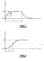
- the pressure measurement curves must be used with regard to their value but also their slope ⁇ as a function of time t.
- the duration T that the measured pressure P puts to pass from the production pressure P1 to the pressure P 2 of the deposit is it equal to a value of between half a day and ten days.
- the pressure curve becomes assimilated, at least during the first phase immediately following closure or full opening, to a general first-order curve in response to a flow step at the valve, characterizing the instantaneous passage between its closed state and its open state or vice versa.
- a steep slope of the curve of Figure 1 indicates a thin skin or a passage section slightly obstructed, providing a higher production yield.
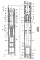
- the pressure response is similar to a curve of order greater than one, such as that shown in FIG. 2, in which the slope of the pressure as a function of time begins to increase to a point of deflection, and then to decrease, until that the pressure goes into steady state.
- the measured pressure curve P it is much more difficult to exploit the measured pressure curve P, since it depends on a larger number of parameters than on the single pass section at the level of the production layer.
- the measured pressure curve P can not be used during the TI time flowing to the point of inflection.
- the aim of the invention is to obtain a valve actuator and a tool equipped with the actuator, which makes it possible to open and / or close the valve as quickly as possible between the last moment when the valve is located. completely in the open and / or closed state and the moment when the valve is completely in the closed and / or open state, so that the flow rate measured downstream of the valve is as close as possible to a step of flow as a function of time, so that the response to the actuation of the valve is as close as possible to the curve according to FIG.
- a first object of the invention is a fast valve actuator according to claim 1.
- the invention allows the rapid movement of the valve between the open or closed position and the closed or open position.
- the actuator is able to cause several movements of opening and closing of the valve. It is thus possible to reassemble the valve and the tool comprising it in the open state after an opening movement or a closing movement followed by an opening movement, which was not possible with valves that can only perform one closure.
- the actuator makes it possible to perform a quick opening and / or closing successively in several successive layers of well production.
- the product fluid carries abrasive materials such as sand and passes through the valve with a very high speed.
- This high speed is due to the large pressure difference between the upstream and downstream sides of the valve, which increases as the fluid passage gap in the valve narrows at the end of closing and at the beginning of opening.
- the fluid produced has a tendency to be applied against the slide or the movable piston of the valve during its closing or opening movement.
- the accumulation of energy in the actuator according to the invention also makes it possible to guarantee that the force exerted on the valve overcomes the resistance between its mobile part and its fixed part, which may be due to the bonding of the sealing means between those this, resulting from the high temperature and pressure conditions prevailing in the well. Consequently, the actuator and the tool comprising the actuator are more reliable.
- a second object of the invention is a tool comprising a valve, having a closed position and an open position, and the actuator of the valve according to any one of claims 1 to 29.
- Other characteristics of the invention are the subject of claims 31 to 36.
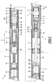
- the actuator 1 comprises an actuator outer body 2 extending in a longitudinal general direction 3 directed from the rear towards the front, for example in the upward direction of the fluid. produced up the well.
- the actuator body 2 comprises means 4 for connection to a body 5 of a valve 6, for example by corresponding threads on the bodies 2 and 5, such as an internal thread 4a on the upper inner end of the body 2 of actuator and a corresponding thread 4b on the lower outer end of the valve body 5, the bodies 2 and 5 being hollow and for example tubular circular cross section.
- the valve 6 has a plurality of holes 7 or holes distributed transversely, for the passage of fluid produced from outside the body 5 to a front space 14 thereof to the top of the well. Of course, only one hole 7 could be provided.
- a piston 8 is slidably mounted in the body 5 facing the hole 7, between the front space 14 and a rear space 15.
- the piston 8 has a wall 11 for supporting first and second outer seals 9, 10 for sealing at fluid produced, spaced longitudinally from the back to the front.
- the valve and the tool of which it is part are placed just above the production layer.
- valve 6 Downstream, the valve 6 is connected to a locking member in the well, for example of the jaw type, spaced in the locking position to the wall of the well.
- the piston 8 of the valve 6 is connected to a rear member 18 for attachment to a front member 19 for fixing a member 21 for actuating the valve 8, between the one and the other of its open positions. and closing the piston 8 is fixedly connected to the fixing member 18 according to Figures 4 to 10 or to Figures 3A to 3C.
- the member 19 before fastening the member 21 is formed by a clamp comprising several branches 191 provided with claws 192 at their free end and elastic from an open position, represented in FIG. 3A and allowing the insertion between them of a fastening piece 181 forming the member 18.
- the body 5 of the valve comprises a rear inner groove 501 cooperating with a corresponding outer chamfer 193 of the claws 192, for to force the branches 191 to close around the attachment piece 181, when it has been inserted between them and then the member 19 of the actuating member 21 and the body 5 are pushed longitudinally l one against the other, as shown in Figure 3B.
- the claws 192 then enter a complementary groove 182 located in front of the attachment piece 181.
- the branches 191 comprise an outer projection 194 for holding the claws 192 in the closed position on the groove 182, when the projections 194 abut against a longitudinal guide wall 502 provided inside the body 5 and in front of the chamfer 501 in the position 3B, in the closed position shown in Figure 3C and between them.
- the fastener 18 is formed in FIGS. 4 to 10 for example by an internal thread cooperating with a corresponding external thread forming the member 19 of the actuating member 21.
- the actuating member 21 extends longitudinally in the housing 2 and comprises, for example, a pin 22 having a front end carrying the member 19 for fastening the piston 8.
- the actuating member 21 is longitudinally movable in the body 2 actuator to move the piston 8 of the valve 6 between one and the other of its open and closed positions.
- the actuating member 21 further comprises a hollow rear longitudinal jacket 23 having a portion 23b before attachment by any appropriate means, for example by screwing, to the rear end of the pin 22.
- a driven member 31 integral in longitudinal translation, at the rear of the sleeve 23, a nut 32 driven cooperating by an internal thread with a longitudinal threaded rod 33 secured to the longitudinal rotating shaft 34 of a drive device 35, for example formed of a geared motor, fixed inside the body 2.
- the threaded rod 33 is for example in the form of a roller recirculating screw for driving the nut 32 in longitudinal translation.
- Geared motor 35 comprises for example a brushless motor.
- the driven member 31 is for example present in the form of a longitudinal pin comprising a portion 36 enclosing the nut 32.
- the geared motor 35, the nut 32 and the driven member 31 are adapted to occupy different longitudinal positions relative to the means 41 for locking and tripping.
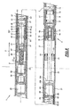
- the driven member 31 comprises in Figures 4, 5 and 6 a first stroke C1 actuating in the body 2 in the direction from the back to the front in the longitudinal direction of the actuator 1 or from bottom to top in the direction of the well, until occupying a first longitudinal position of trigger, shown in Figure 7, in which the passage of the valve position opening to the closed position is caused.
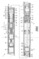
- the driven member 31 comprises in Figures 8, 9 and 10 a second stroke C2 of longitudinal actuation directed in the opposite direction of the first stroke C1, from the front to the rear of the actuator 1 or from top to bottom. bottom of the well, from the first trigger position to a second longitudinal trigger position, moved back relative to the first and shown in Figure 4, wherein the passage of the valve from the closed position to the position opening is provoked.
- first and second longitudinal trigger positions could be provided.
- the driven member 31 In each of the first and second triggering positions, the driven member 31 is fixed longitudinally relative to the locking and tripping means 41, while the actuating member 21 is pushed longitudinally with respect to the locking means 41 and triggering by a prestressing means 51 provided between the driven member 31 and the actuating member 21 respectively forward and backward, to pass the actuating member 21 respectively in first and second longitudinal positions respectively corresponding to the closing and opening positions of the valve 6.
- the positioning of the driven member 31 in the latter causes the preloading means 51 to move the actuating member 21 only in the second position, corresponding to the passage of the valve 6. from the closed position to the open position.
- the driven member 31 comprises a first pusher 37 to push longitudinally forwards the pretensioning means 51 during the first stroke C1 to arrive at the first release position, and a second pusher 38 to push longitudinally towards the first rear biasing means 51 during the second stroke C2 to arrive at the second trigger position.
- the prestressing means 51 is for example formed by a helical compression spring inserted in the liner 23 between the first and second pushers 37, 38 around a longitudinal central pin 39 integrally connecting the first and second to each other. pushers 37, 38.
- the first pusher 37 acts on the prestressing means 51 via a first spacer 61 mounted longitudinally movable between the prestressing means 51 and the first pusher 37 and for example formed by a washer threaded by a hole of a smaller cross-section. that of the first pusher 31 around the pin 39 in front of it.
- the second pusher 38 acts on the pre-stressing means 51 via a second spacer 62 mounted to move longitudinally between the prestressing means 51 and the second pusher 38 and for example formed by a washer threaded by a hole of a lower cross section. that of the second pusher 31 around the pin 39 behind it.
- first stop 63 of the liner 23 of upper section to the first pusher 31 and the pin 39 to slide longitudinally
- second stop 64 of the shirt 23 upper section to the second pusher 38 and pin 39, to let them slide longitudinally.
- the first and second stops 63, 64 are spaced apart by the same length L as the first and second pushers 37, 38.
- the first pusher 31 advances the first spacer 61 in front of the first stop 63 as shown in FIG. 6, while the sleeve 23 is locked longitudinally by the means 41 for locking and tripping, which blocks the second spacer 62 forwards against the second stop 64 and therefore reduces the distance between the first and second spacers 61, 62, at a distance less than the distance L, thus compressing the spring 51.
- the liner 23 has an additional space 65 in front of the second pusher 38 to house it during its first race C1 to the first trigger position.
- the second pusher 38 pushes the second spacer 62 rearwardly behind the second stop 64 as shown in FIG. 9, while the sleeve 23 is blocked. longitudinally by the locking and tripping means 41, which keeps the first spacer 61 against the first stop 63 and therefore reduces the distance between the first and second struts 61, 62, at a distance less than the distance L, thereby compressing the spring 51.
- An additional space 66 is provided in the liner 23 behind the first stop 63 to accommodate the first pusher 37 retreating into the liner 23 behind the first stop 63 during its second race C2.
- the driven member 31 comprises, connected in front of the portion 36, a sheath 67 for receiving the front end of the threaded rod 33 during the races C1 and C2 and in the first and second trigger positions.
- the sheath 67 is connected to the front to a longitudinal guide piece 47 having a length L2 greater than or equal to the length of the first stroke C1 to the first release position and the length of the second stroke C2 to the second release position
- the means 41 for locking and tripping comprises a support 42 fixed inside the body 2 in front of the portion 36 and the nut 32 around the sheath 67 and the guide piece 47.
- the support 42 is formed of a longitudinal wall, which surrounds the guide piece 47 and which comprises one or more housings 44, in which are inserted transversely to the longitudinal direction, and for example radially, respectively one or more pieces 43 jamming.
- the housing or the housing 44 are for example each in the form of a through hole being in the same prescribed longitudinal position of the longitudinal wall of the support 42.
- the housing 44 When several housing 44 and 43 associated parts are provided, the housing 44 are separated into the same longitudinal position prescribed by solid parts of the longitudinal wall of the support 42, that is to say that the housing 44 are aligned transversely, so that each wedging piece has a limited stroke in its associated housing 44 around the longitudinal direction 3.
- the guide piece 47, the wedge piece or parts 43, and a rear portion 68 of the jacket 23 surrounding the support 42 are configured so as to face each other transversely during the first and second races C1 and C2 and in the first and second trigger positions.
- the guide piece 47 has on its outer surface, for each wedge piece 43, a first transverse recess 45 of housing, while the rear portion 24 of the sleeve 23 comprises, for each piece 43 of wedging, a second transverse recess 46 housing for coin 43 of jamming.
- first transverse recess 45 When several recesses 45 are provided, they are aligned transversely.
- second recesses 46 When several recesses 46 are provided, they are aligned transversely.
- the first and second recesses 45, 46 are able to face each other transversely when the first stroke C1 reaches the first release position, to move the wedge piece 43 from the second recess 46 to the first recess 45.
- the guide piece 47 comprises, in front of the first recess or recesses 45 and for each wedging piece 43, a third transverse recess 49 for accommodating the wedge piece 43 in the second trigger position, while the part rear 24 of the liner 23 comprises, behind the second or second recesses 46 and for each part 43 wedging, a fourth transverse recess 50 housing for the coin 43 jamming.
- a third transverse recess 49 for accommodating the wedge piece 43 in the second trigger position
- the part rear 24 of the liner 23 comprises, behind the second or second recesses 46 and for each part 43 wedging, a fourth transverse recess 50 housing for the coin 43 jamming.
- the third and fourth recesses 49, 50 are able to face each other transversely when the second stroke C2 reaches the second release position, to move the wedge piece 43 from the fourth recess 50 to the third recess 49.
- the sleeve 23 comprises around and between its recesses 46, 50 a closing wall 231, mounted on it after insertion of
- the wedge piece 43 is in the fourth recess 50 of the rear portion 24 of the jacket 23 and out of the third recess 49 shifted longitudinally relative to the recess 50, so as to make the support 42 and the liner 23 longitudinally integral and to allow the longitudinal displacement of the guide piece 47 with respect to the wedge piece 43.
- the jamming piece 43 falls into the third recess 49 and leaves the fourth recess 50 then being face to face transversely, to make the guide piece 47 transversely integral with the support 42 and to allow the displacement longitudinal direction towards the rear of the liner 23, thanks to the force exerted by the means 51 of backward prestressing on the first spacer 61 and the first stop 63.
- the wedge piece 43 is for example formed, as shown, by a ball, the recesses 45, 49 of the driven member 31 being of corresponding shape, for example hemispherical.
- the recess 46 and / or 50 of the liner 23 is for example a circular hole of diameter greater than that of the ball to allow its introduction into the support 42 from the outside.
- the housing 44 is for example also a circular hole of diameter greater than that of the ball, in the wall of the support 42.
- the wedge piece 43 could also be formed by a roll with a cylindrical surface, the recesses 45, 49 provided in the driven member 31 then also of hollow cylindrical shape, for example in the form of circular half-cylinder, while the recesses 46, 50 are corresponding oblong holes for the introduction of the wedge piece 43 in the support 42 through the portion 24.
- the housing 44 is for example in the form of an oblong through hole Rectangular dimensions following the generatrices and bases of the roll in the wall of the support 42.
- the passage of the valve 6 from the open position to the closed position is caused by prior accumulation of energy in the prestressing means 51, for example by compression for a spring 51 in the jacket 23, during the first stroke C1, until the driven member 31 reaches the first trigger position.
- the first trigger position releases energy accumulated in the prestressing means 51 during the first stroke C1 to move the actuating member 21 from the open position to the closed position.
- the force exerted on the actuating member 21 in the triggering position or positions depends on the capacity of the prestressing means 51 for storing energy, that is to say for a spring of its stiffness, of its prestressing value and its stroke.
- the prestressing means 51 is provided in such a way that any resistance forces between the piston 8 and the body 5 of the valve 6 are overcome, the initial force exerted by the prestressing means 51 in the release position. being for example several times greater than, and for example equal to at least three or ten times, this resistance force.
- the prestressing means 51 is provided in the form of a helical spring already compressed longitudinally between the spacers 61, 62, when they are spaced from their greater distance.
- the prestressing means 51 may also be provided in the form of a corrugated coil spring. After triggering an opening or closing, the spring 51 continues to exert a force on the actuating member 21 for maintain the valve 6 respectively in the open or closed position it has just taken.
- the closing time of the valve elapsed between the last moment when the piston 8 is stationary relative to the body 5 of the valve 6 in the open position and the first moment when it is in the closed position is very short and of duration less than one second, while the known valves perform a closing movement of the valve in more than 50 seconds.
- the guide piece 47 comprises a central support pin 471, which is integral with the sheath 67 and the pusher 37 and which has at its ends the first and / or third recesses 45, 49, whose longitudinal halves 451, 491 furthest away from each other are similar to those of FIGS. 4 to 9 and of which the nearest longitudinal halves 452, 492 of one another are formed by a straight profile groove and a right angle connected to center pin 471.
- a guide sleeve 472 is mounted movably longitudinally around the central support pin 471.
- the guiding sleeve 472 comprises an outer surface 473 for guiding the wedge piece (s) 43, in a manner similar to the guiding piece 47 according to FIGS. 4 to 9.
- the outer guiding surface 473 is connected to front transverse edges 474 and 475 rear separated from each other by a length substantially equal to the distance between the middle of the first recess 45 and the furthest end of the third obviously 49.
- the wedge piece (s) 43 are against the outer guide surface 473 during the strokes C1 and C2.
- the coin (s) 43 wedge reach the rear transverse edge 475.
- the piece (s) ) 43 from the recess 46 in the first recess 45, push longitudinally and jointly forward the rear transverse edge 475 until the guide sleeve 472 abuts against the front half 491 of the obviously 49.
- the process is similar for the second race C2 and the second trigger position
- each lug 431 is provided with a jaw 433 forming wedge piece 43, having an outer portion 434 facing the liner 23 and of longitudinal section of complementary shape of the second and fourth recesses 46, 50, and a portion Inner 435 facing the guide piece and longitudinal section complementary shape of the first and third recesses 45, 49.
- the recesses 45, 46, 49, 50 are for example in the form of rectilinear profile grooves formed respectively in the guide piece 47 and in the jacket 23, the wall 231 being in one piece with the jacket 23.
- Ramps complementary parts are provided on the parts 434, 435 and in the recesses 45, 46, 49, 50 to allow the longitudinal locking of the liner 23 or the driven member 31 relative to the tabs 431.
- the tabs 431 are made of a material having a certain flexibility allowing them to flex transversely in order to be able to pass from one recess 50, 46 to the other 45, 46 in the first and second trigger position and to be in the recess. 46 or 50, against the guide piece 47 and between its recesses 45 and 49 in the races C1 and C2.
- the passage control of the actuating member 21 in the first or second triggering position is effected by controlling the driving device 35 to move the nut 32 to corresponding longitudinal positions on the rod. threaded 33.
- This command is performed for example by controlling energy supply means of the drive device 35, not shown and shipped with the actuator and / or tool at the bottom of the well.
- these power supply means are provided in the form of a battery or an electric battery which is controlled to connect to the drive device 35 to rotate in one direction or another its shaft 34 during the race C1 or C2.
- the supply means can be provided so that it can perform several races C1 and C2 without having to recharge or change them, which gives the actuator greater autonomy.
- the actuator body 2 has at its rear end a sealed bushing 81 for electrically connecting the drive device 35 to supply and control means, provided in a housing fixed to the body 2 of the actuator or extending from one piece this one.
- the drive device 35 comprises, for example, counting means of turns of its shaft 34 and is for example a brushless drive device.
- the power supply of the actuator can also be performed by cable connected on the surface to an electrical source.
- the control of the actuator can also be preprogrammed on the surface before it descends into the well. The connection of the supply means to the actuator then causes the prerecorded program to run in the actuator.
- sealing means 71 are for example provided in the form of a piston surrounding the pin 22 in the body 2 and bearing on its outer peripheral face facing the inside of the housing 2 a first seal 72 and on its inner face facing the pin 22 a second seal 73.
- the piston 71 is advantageously slidably mounted relative to the spindle 22 and to the body 2, in order to balance the pressure differences prevailing on either side longitudinally thereof. The seals 72 and 73 are thus better preserved from pressure differences on either side longitudinally.
- the internal space of the body 2 located behind the sealing means 71 is filled with an operating fluid, for example to a large extent incompressible in the operating conditions of the well.
- This operating fluid is, for example, an oil.
- the piston 8 of the valve 6 is connected with a longitudinal displacement to the fixing member 18 according to FIGS. 4 to 10 or according to FIGS. 3A to 3C.
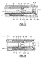
- the fixing member 18 comprises at its front end a transverse shoulder 183 inserted longitudinally sliding in a rear housing 184 of the piston 8, delimited by front stops 185 and rear 186 thereof, which define between them a longitudinal deflection determined for the shoulder 183, less than the length between its open and closed position.
- the shoulder 183 When the valve 6 is kept open, the shoulder 183 is held by the members 18, 19 and 21 against the rear stop 186, whereas when the valve 6 is kept closed as shown in FIG. 13, the shoulder 183 is maintained by the members 18, 19 and 21 against the stop before 185. When it is then closed or opened the valve 6 from the open or closed position, the clearance of the shoulder 183 allows to make it arrive with a high speed in the corresponding direction against the opposite stop 185 or 186, thus exerting a shock on the piston 8, helping to take off its joints 9,10 relative to the body 5.
- the piston 8 of the valve 6 comprises a single outer front seal 10 and an inner rear inner chamber 111 which can communicate on the one hand by a transverse duct 112 with the outside of its support wall 11 and on the other side. on the other hand by a longitudinal duct 113 with the front space 14.
- the transverse duct 112 opens into the hole 7.
- the ducts 112 and 113 have a fluid passage section produced in the well, lower than that of the hole 7.
- the chamber 111 is further delimited at the rear by a secondary piston 114 mounted longitudinally sliding and fixed to the member 18 in front of the shoulder 183.
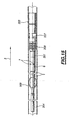
- the actuator 1 can be integrated into a tool 201.
- a tool 201 can comprise, in addition to the actuator 1 and the valve 6, a unit 204 comprising pressure, temperature, flow rate and / or other parameters under the actuator 1 and means for recording the measurement information produced by the sensors.
- the tool 201 comprises, mechanically connected to each other from top to bottom, a member 207 for locking by anchoring against the conduit 203, having seals 208 for sealing the fluid produced against the conduit 203, the valve 6 , the actuator 1, an optional centralizer 209 with arches against the conduit 203 and the unit 204.
Landscapes
- Engineering & Computer Science (AREA)
- Geology (AREA)
- Life Sciences & Earth Sciences (AREA)
- Mining & Mineral Resources (AREA)
- Geochemistry & Mineralogy (AREA)
- Fluid Mechanics (AREA)
- Environmental & Geological Engineering (AREA)
- General Life Sciences & Earth Sciences (AREA)
- Physics & Mathematics (AREA)
- Mechanical Engineering (AREA)
- Mechanically-Actuated Valves (AREA)
- Actuator (AREA)
- Portable Nailing Machines And Staplers (AREA)
- Vehicle Body Suspensions (AREA)
- Valve Device For Special Equipments (AREA)
- Infusion, Injection, And Reservoir Apparatuses (AREA)
- Valve Housings (AREA)
- Dowels (AREA)
- Preventing Unauthorised Actuation Of Valves (AREA)
Claims (36)
- Ventilschnellbetätiger, umfassend- einen Betätigerkörper (2),- ein Ventilbetätigungsorgan (21), das im Betätigerkörper (2) zwischen einer Ventilschließstellung und einer Ventilöffnungsstellung beweglich ist,dadurch gekennzeichnet, dass das Betätigungsgerät außerdem umfasst:- eine Antriebsvorrichtung (35) im Betätigerkörper (2),- ein von der Antriebsvorrichtung (35) relativ zum Betätigerkörper (2) angetriebenes Organ, wobei die Antriebsvorrichtung (35) geeignet ist, das angetriebene Organ (31) über einen ersten Weg (C1) zu einer ersten Auslösestelle zu bringen,- ein Mittel (51) zum Vorspannen des Betätigungsorgans (21) relativ zum angetriebenen Organ (31), um zwischen diesen, wenn das angetriebene Organ (31) auf seinem ersten Weg (C1) zu seiner ersten Auslösestellung gelangt, eine Abstoßungskraft auszuüben, die anstrebt, das Betätigungsorgan (21) mindestens aus einer ersten festgelegten Stellung unter den Stellungen der Ventilöffnung und des Ventilschließens in die festgelegte zweite Stellung unter den Stellungen der Ventilöffnung und des Ventilschließens zu bringen,- ein Verriegelungs- und Auslösemittel (41), das relativ zum Betätigerkörper (2) feststeht und mit dem angetriebenen Organ (31) und dem Betätigungsorgan (21) zusammenarbeitet, damit- das Betätigungsorgan (21) auf dem ersten Weg (C1) in der ersten festgelegten Stellung relativ zum Verriegelungs- und Auslösemittel (41) feststeht und das angetriebene Organ (31) relativ zum Verriegelungs- und Auslösemittel (41) beweglich ist,- das angetriebene Organ (31), wenn sich das angetriebene Organ (31) in der ersten Auslösestellung befindet, relativ zum Verriegelungs- und Auslösemittel (41) feststeht und das Betätigungsorgan (21) durch das Vorspannmittel (51) relativ zum Verriegelungs- und Auslösemittel (41) derart geschoben wird, dass das Betätigungsorgan (21) aus der ersten festgelegten Stellung in die zweite festgelegte Stellung übergeht.
- Ventilschnellbetätiger nach Patentanspruch 1, dadurch gekennzeichnet, dass die Antriebsvorrichtung (35) geeignet ist, das angetriebene Organ (31) über einen zweiten Weg (C2) in eine zweite Auslösestellung zu bringen, wobei das Vorspannmittel (41) geeignet ist, zu dem Zeitpunkt, wo das angetriebene Organ (31) über seinen zweiten Weg (C2) in seine zweite festgelegte Auslösestellung übergeht, eine Abstoßungskraft zwischen diesen auszuüben, die anstrebt, das Betätigungsorgan (21) aus der zweiten festgelegten Stellung in die erste festgelegte Stellung zu bringen, und das Verriegelungs- und Auslösemittel (41) derart ausgebildet ist, dass es mit dem angetriebenen Organ (31) und dem Betätigungsorgan (21) zusammenarbeitet, damit- das Betätigungsorgan (21) auf dem zweiten Weg (C2) in der zweiten festgelegten Stellung relativ zum Verriegelungs- und Auslösemittel (41) feststeht und das angetriebene Organ (31) relativ zum Verriegelungs- und Auslösemittel (41) beweglich ist,- das angetriebene Organ (31), wenn sich das angetriebene Organ (31) in der ersten Auslösestellung befindet, relativ zum Verriegelungs- und Auslösemittel (41) feststeht und das Betätigungsorgan (21) durch das Vorspannmittel (51) derart relativ zum Verriegelungs- und Auslösemittel (41) geschoben wird, dass es aus der zweiten festgelegten Stellung in die erste festgelegte Stellung übergeht.
- Ventilschnellbetätiger nach irgendeinem der vorangehenden Patentansprüche, dadurch gekennzeichnet, dass der Weg (C1, C2) in Längsrichtung verläuft, das Betätigungsorgan (21) in Längsrichtung zwischen der Ventilschließstellung und der Ventilöffnungsstellung beweglich ist, das angetriebene Organ (31) relativ zum Betätigerkörper (2) in Längsrichtung auf dem Weg (C1, C2) beweglich ist.
- Ventilschnellbetätiger nach Patentanspruch 3, dadurch gekennzeichnet, dass das Verriegelungs- und Auslösemittel (41) umfasst:- mindestens ein Klemmteil (43), das quer zum Betätigerkörper (2) beweglich ist,- eine erste und eine zweite Ausnehmung (45, 46) zur Aufnahme des Klemmteils (43) im angetriebenen Organ (31) bzw. im Betätigungsorgan (21), wobei die erste und zweite Ausnehmung (45, 46) mindestens in Längsrichtung auf dem ersten Weg bis zur ersten Auslösestellung versetzt sind, damit sich das Klemmteil (43) außerhalb der ersten Ausnehmung (45) des angetriebenen Organs (31) befindet und in der zweiten Ausnehmung (46) des Betätigungsorgans (21), um das Betätigungsorgan (21) mit dem Träger (42) in Längsrichtung fest zu verbinden und die Bewegung des angetriebenen Organs (31) relativ zum Träger (42) in Längsrichtung zu ermöglichen, und sich die erste und die zweite Ausnehmung (45, 46) in der ersten Auslösestellung in Querrichtung einander gegenüber befinden, damit das Klemmteil (43) aus der zweiten Ausnehmung (45) des angetriebenen Organs (31) austreten kann, um das angetriebene Organ (31) mit dem Träger (42) in Längsrichtung fest zu vebinden und die Bewegung des Betätigungsorgans (21) relativ zum Träger (42) in Längsrichtung zu ermöglichen.
- Ventilschnellbetätiger nach den Patentansprüchen 2 und 4, dadurch gekennzeichnet, dass das Verriegelungs- und Auslösemittel (41) eine dritte und eine vierte Ausnehmung (49, 50) zur Aufnahme des Klemmteils (43) im angetriebenen Organ (31) bzw. im Betätigungsorgan (21) umfasst, wobei die dritte Ausnehmung von der ersten Ausnehmung (45) in Längsrichtung beabstandet ist und die dritte und die vierte Ausnehmung (49, 50) mindestens in Längsrichtung auf dem zweiten Weg bis zur zweiten Auslösestellung versetzt sind, damit sich das Klemmteil (43) außerhalb der dritten Ausnehmung (49) des angetriebenen Organs (31) befindet und in der vierten Ausnehmung (50) des Betätigungsorgans (21), um das Betätigungsorgan (21) mit dem Träger (42) in Längsrichtung fest zu verbinden, und die Bewegung des angetriebenen Organs (31) relativ zum Träger (42) in Längsrichtung zu ermöglichen, und sich die dritte und die vierte Ausnehmung (49, 50) in der zweiten Auslösestellung in Querrichtung einander gegenüber befinden, damit das Klemmteil (43) aus der vierten Ausnehmung (50) des Betätigungsorgans (21) aus- und in die dritte Ausnehmung (49) des angetriebenen Organs (31) eintreten kann, um das angetriebene Organ (31) mit dem Träger (42) in Längsrichtung fest zu verbinden und die Bewegung des Betätigungsorgans (21) relativ zum Träger (42) in Längsrichtung zu ermöglichen.
- Ventilschnellbetätiger nach irgendeinem der Patentansprüche 4 und 5, dadurch gekennzeichnet, dass das Klemmteil (43) in einem Träger (42) in Querrichtung frei beweglich montiert ist, der relativ zum Betätigerkörper (2) feststeht und in Querrichtung zwischen dem angetriebenen Organ (31) und dem Betätigungsorgan (21) angeordnet ist.
- Ventilschnellbetätiger nach Patentanspruch 6, dadurch gekennzeichnet, dass das Klemmteil (43) aus einer Kugel besteht.
- Ventilschnellbetätiger nach Patentanspruch 6, dadurch gekennzeichnet, dass das Klemmteil (43) aus einer Rolle besteht.
- Ventilschnellbetätiger nach irgendeinem der Patentansprüche 4 bis 8, dadurch gekennzeichnet, dass das angetriebene Organ (31) ein Führungsteil (47) aufweist, das während des Durchlaufens des genannten Weges mit dem Klemmteil (43) fest verbunden ist.
- Ventilschnellbetätiger nach irgendeinem der Patentansprüche 4 bis 9, dadurch gekennzeichnet, dass das Klemmteil (43) aus einer Spannbacke (433) einer in Querrichtung flexiblen Klaue (431) besteht und in Längsrichtung mit Abstand zur Backe (433) an einem relativ zum Körper (2) festen Teil (432) befestigt ist.
- Ventilschnellbetätiger nach irgendeinem der Patentansprüche 4 bis 8, dadurch gekennzeichnet, dass das angetriebene Organ (31) ein festes Tragteil (471) aufweist, auf dem eine Hülse (472) zur Führung des Klemmteils (43) während des Durchlaufens des genannten Weges in Längsrichtung beweglich angebracht ist, wobei die Führungshülse (472) geeigent ist, durch das Klemmteil (43) in Längsrichtung geschoben zu werden, wenn das Klemmteil (43) in die Ausnehmung (45, 46) des angetriebenen Organs (31) einrückt.
- Ventilschnellbetätiger nach irgendeinem der Patentansprüche 4, 5, 6, 7, 8, 9, 11, dadurch gekennzeichnet, dass mindestens eine der im Betätigungsorgan (21) vorgesehenen Ausnehmungen (46, 50) nach außen offen ist, um das Einführen des Klemmteils (43) in den Träger (42) zu ermöglichen.
- Ventilschnellbetätiger nach irgendeinem der vorangehenden Patentansprüche, dadurch gekennzeichnet, dass die erste Stellung der Öffnungsstellung des Ventils entspricht und die zweite Stellung der Schließstellung des Ventils.
- Ventilschnellbetätiger nach irgendeinem der Patentansprüche 1 bis 12, dadurch gekennzeichnet, dass die erste Stellung der Schließstellung des Ventils entspricht und die zweite Stellung der Öffnungsstellung des Ventils.
- Ventilschnellbetätiger nach irgendeinem der vorangehenden Patentansprüche, dadurch gekennzeichnet, dass das Vorspannmittel (51) derart beschaffen ist, dass es die Abstoßungskraft zwischen dem Betätigungsorgan (21) und dem angetriebenen Organ (31) erhöht, wenn das angetriebene Organ (31) auf seinem Weg (C1, C2) in seine Auslösestellung gelangt, und dass es in seiner zweiten festgelegten Stellung eine Kraft zum Festsetzen des Betätigungsorgans ausübt.
- Ventilschnellbetätiger nach irgendeinem der vorangehenden Patentansprüche, wenn er mindestens vom Patentanspruch 3 abhängt, dadurch gekennzeichnet, dass das Betätigungsorgan (21) eine Spindel (22) aufweist, die mit einem Futterrohr (23) fest verbunden ist, das angetriebene Organ (31) eine Spindel (39) aufweist, die im Futterrohr (23) in Längsrichtung beweglich ist und mindestens einen ersten Drücker (37) zum Schieben des Vorspannmittels (51) in Längsrichtung aufweist, wenn das angetriebene Organ (31) auf seinem Weg (C1, C2) in die Auslösestellung gelangt, wobei ein zweiter Drücker (38) zwischen dem Vorspannmittel (51) und dem Futterrohr (23) vorgesehen ist.
- Ventilschnellbetätiger nach Patentanspruch 12, dadurch gekennzeichnet, dass das Futterrohr (23) einen ersten und einen zweiten Anschlag (63, 64) für eine erste und eine zweite Abstandshülse (61, 62) aufweist, die zwischen dem Vorspannmittel (51) und dem ersten bzw. dem zweiten Drücker (37, 38) beweglich montiert sind, wobei das Futterrohr (23) einen ersten und einen zweiten Zusatzraum (66, 65) für das Eindringen des ersten bzw. des zweiten Drückers (37, 38) aufweist, wenn das angetriebene Organ (31) seinen Weg (C1, C2) bis zur zugehörigen Auslösestellung in Längsrichtung durchläuft.
- Ventilschnellbetätiger nach irgendeinem der vorangehenden Patentansprüche, dadurch gekennzeichnet, dass das Vorspannmittel (51) aus einer Druckfeder zwischen dem Betätigungsorgan (21) und dem angetriebenen Organ (31) besteht.
- Ventilschnellbetätiger nach Patentanspruch 18 und irgendeinem der Patentansprüche 16 und 17, dadurch gekennzeichnet, dass die Druckfeder eine zylindrische Schraubenfeder ist und um die Spindel (39) des angetriebenen Organs (31) eingerollt ist.
- Ventilschnellbetätiger nach Patentanspruch 14 und irgendeinem der Patentansprüche 16 und 17, dadurch gekennzeichnet, dass die Druckfeder wellenförmige Windungen um die Spindel (39) des angetriebenen Organs (31) aufweist.
- Ventilschnellbetätiger nach irgendeinem der vorangehenden Patentansprüche, wenn er mindestens vom Patentanspruch 3 abhängt, dadurch gekennzeichnet, dass das angetriebene Organ (31) eine Mutter (32) aufweist, die im Betätigerkörper (2) rotationsfest ist und mit einer Gewindestange (33) zusammenarbeitet, die durch die Antriebsvorrichtung (35) in Drehung versetzt wird, um das angetriebene Organ (31) in Längsrichtung zu verschieben.
- Ventilschnellbetätiger nach irgendeinem der vorangehenden Patentansprüche, dadurch gekennzeichnet, dass er zwischen dem Betätigergehäuse (2) und dem Betätigungsorgan (21) Mittel (71) zur Abdichtung der Antriebsvorrichtung (35), des angetriebenen Organs (35), des Vorspannmittels (51) und des Verriegelungs- und Auslösemittels (41) nach außen aufweist.
- Ventilschnellbetätiger nach Patentanspruch 22, dadurch gekennzeichnet, dass die Dichtungsmittel (71) einen Kolben umfassen, der in Längsrichtung gleitend am Betätigungsorgan (21) entlang montiert ist, wobei der Kolben der Dichtungsmittel (71) Dichtungen (72, 73) trägt, die an das Innere des Betätigergehäuses (2) bzw. an das Betätigungsorgan (21) angedrückt werden.
- Ventilschnellbetätiger nach Patentanspruch 22 oder 23, dadurch gekennzeichnet, dass der Innenraum des Betätigerkörpers (2), der sich hinter den Dichtungsmitteln (71) befindet und das Antriebsmittel (35), das angetriebene Organ (31), das Vorspannmittel (51) und das Verriegelungs- und Auslösemittel (41) enthält, mit einem Betriebsfluid gefüllt ist.
- Ventilschnellbetätiger nach Patentanspruch 24, dadurch gekennzeichnet, dass das Betriebsfluid ein Schmieröl ist.
- Ventilschnellbetätiger nach irgendeinem der vorangehenden Patentansprüche, dadurch gekennzeichnet, dass der Betätigerkörper (2) außerdem eine abgedichtete Durchführung (81) zur elektrischen Verbindung der Antriebsvorrichtung (35) mit Mitteln zur Energieversorgung und zu seiner Betätigung umfasst, die im Betätigungsgerät eingebaut sind.
- Ventilschnellbetätiger nach irgendeinem der vorangehenden Patentansprüche, dadurch gekennzeichnet, dass die Antriebsvorrichtung (35) ein Getriebemotor ist.
- Ventilschnellbetätiger nach irgendeinem der vorangehenden Patentansprüche, dadurch gekennzeichnet, dass die Antriebsvorrichtung (35) einen Stromrichtermotor umfasst.
- Ventilschnellbetätiger nach irgendeinem der vorangehenden Patentansprüche, dadurch gekennzeichnet, dass die Antriebsvorrichtung einen Rollengewindetrieb mit Rollenrückführung (33) zum Antrieb einer Mutter (32) des angetriebenen Organs (31) umfasst.
- Werkzeug, ein Ventil umfassend, das über eine Schließstellung und eine Öffnungsstellung verfügt, und einen Ventilschnellbetätiger nach irgendeinem der vorangehenden Patentansprüche.
- Werkzeug nach Patentanspruch 30, dadurch gekennzeichnet, dass es außerdem mindestens einen Messsensor (204) umfasst und Mittel zur Speicherung der Messinformationen des Sensors (204), wobei sich der Betätiger (1) in Längsrichtung zwischen dem Ventil (6) und dem genannten Sensor (204) befindet.
- Werkzeug nach irgendeinem der Patentansprüche 30 und 31, dadurch gekennzeichnet, dass das Ventil einen Kolben (8) aufweist, der zwischen der Schließstellung und der Öffnungsstellung mindestens eines Loches (7) eines Ventilkörpers (5) beweglich montiert ist, das relativ zu einem Fluiddurchflussraum (14) nach außen mündet, und der mit einem Organ (18) zur Befestigung an einem entsprechenden Organ (19) des Betätigungsorgans (21) verbunden ist.
- Werkzeug nach Patentanspruch 32, dadurch gekennzeichnet, dass das Befestigungsorgan (18) aus einem Gewinde besteht, das mit einem entsprechenden Gewinde zusammenarbeitet, das das entsprechende Organ (19) des Betätigungsorgans (21) bildet.
- Werkzeug nach Patentanspruch 32, dadurch gekennzeichnet, dass das entsprechende Organ (19) des Betätigungsorgans (21) aus einer Zange besteht, die über mehrere elastische Arme (191) verfügt, die geeignet sind, eine nach außen offene Stellung einzunehmen, die das Einführen eines Halteteils (181) erlaubt, das das Befestigungsorgan (18) bildet, wenn sie sich außerhalb einer Führungswand (502) befinden, die im Ventil vorgesehen ist, und die geeignet sind, das Halteteil (181) zu umgreifen, wenn sie sich zwischen der Schließ- und der Öffnungsstellung an der Führungswand (502) befinden.
- Werkzeug nach irgendeinem der Patentansprüche 32 bis 34, dadurch gekennzeichnet, dass der Kolben (8) des Ventils (6) mit einem bestimmten Spiel in Längsrichtung mit dem Befestigungsorgan (18) verbunden ist, das geringer ist, als der Abstand zwischen seiner Öffnungs- und seiner Schließstellung.
- Werkzeug nach irgendeinem der Patentansprüche 32 bis 35, dadurch gekennzeichnet, dass das Ventil (6) außerdem einen Unterkolben (114) aufweist, der gleitend in einer Kammer (111) des Kolbens (8) montiert ist, die Nebenverbindungsmittel (112, 113) für das Fluid zwischen dem Loch (7) und dem Fluiddurchflussraum (14) aufweist, der mit dem Betätigungsorgan (21) verbunden ist, der die Kammer (111) des Kolbens (8) in Schließstellung verschließt, und der geeignet ist, beim Übergang des Betätigungsorgans (21) von der Schließstellung in die Öffnungsstellung das Loch (7) über die Nebenverbindungsmittel (112, 113) mit dem Fluiddurchflussraum (14) zu verbinden.
Applications Claiming Priority (3)
| Application Number | Priority Date | Filing Date | Title |
|---|---|---|---|
| FR0209400 | 2002-07-24 | ||
| FR0209400A FR2842881B1 (fr) | 2002-07-24 | 2002-07-24 | Actionneur rapide de vanne et outil muni de celui-ci |
| PCT/FR2003/002083 WO2004011769A1 (fr) | 2002-07-24 | 2003-07-04 | Actionneur rapide de vanne et outil muni de celui-ci |
Publications (2)
| Publication Number | Publication Date |
|---|---|
| EP1540132A1 EP1540132A1 (de) | 2005-06-15 |
| EP1540132B1 true EP1540132B1 (de) | 2006-10-04 |
Family
ID=30011452
Family Applications (1)
| Application Number | Title | Priority Date | Filing Date |
|---|---|---|---|
| EP03771131A Expired - Lifetime EP1540132B1 (de) | 2002-07-24 | 2003-07-04 | Schnellventilstellglied und damit versehenes werkzeug |
Country Status (10)
| Country | Link |
|---|---|
| US (1) | US7114697B2 (de) |
| EP (1) | EP1540132B1 (de) |
| CN (1) | CN100343477C (de) |
| AT (1) | ATE341698T1 (de) |
| AU (1) | AU2003260659A1 (de) |
| BR (1) | BRPI0313032B1 (de) |
| CA (1) | CA2492920C (de) |
| DE (1) | DE60308882D1 (de) |
| FR (1) | FR2842881B1 (de) |
| WO (1) | WO2004011769A1 (de) |
Families Citing this family (14)
| Publication number | Priority date | Publication date | Assignee | Title |
|---|---|---|---|---|
| US7819198B2 (en) * | 2004-06-08 | 2010-10-26 | Birckhead John M | Friction spring release mechanism |
| US7823633B2 (en) * | 2007-10-09 | 2010-11-02 | Mark David Hartwell | Valve apparatus |
| US20090090879A1 (en) * | 2007-10-09 | 2009-04-09 | Mark David Hartwell | Valve apparatus |
| US8424842B2 (en) * | 2009-04-15 | 2013-04-23 | Baker Hughes Incorporated | Rotationally-actuated flapper valve and method |
| US8453748B2 (en) | 2010-03-31 | 2013-06-04 | Halliburton Energy Services, Inc. | Subterranean well valve activated with differential pressure |
| US8522887B1 (en) * | 2010-05-18 | 2013-09-03 | Kent R. Madison | Aquifier flow controlling valve assembly and method |
| GB2489987B (en) * | 2011-04-15 | 2013-07-10 | Aker Well Service As | Downhole fast-acting shut-in valve system |
| US9151139B2 (en) * | 2011-06-02 | 2015-10-06 | Baker Hughes Incorporated | Method of reducing deflection through a rod piston in a subsurface safety valve |
| WO2014019154A1 (zh) * | 2012-08-01 | 2014-02-06 | 思达斯易能源技术(集团)有限公司 | 洗井阀 |
| US9784068B2 (en) * | 2014-10-01 | 2017-10-10 | Cameron International Corporation | Stem guide system |
| US10107072B2 (en) * | 2016-03-15 | 2018-10-23 | Tercel Oilfield Products Usa Llc | Toe valve |
| RU2623750C1 (ru) * | 2016-10-14 | 2017-06-29 | Петр Игоревич Сливка | Способ проведения подземного ремонта скважины для смены погружного оборудования и исключения влияния раствора глушения на продуктивный пласт |
| US12460495B2 (en) | 2022-04-11 | 2025-11-04 | Schlumberger Technology Corporation | Systems and methods for single trip gravel packing in open hole borehole |
| CA3180354A1 (en) * | 2022-10-28 | 2024-04-28 | Dynomax Drilling Tools Inc. | Electrically activated downhole valve for drilling applications |
Family Cites Families (5)
| Publication number | Priority date | Publication date | Assignee | Title |
|---|---|---|---|---|
| US3889751A (en) * | 1974-02-01 | 1975-06-17 | Exxon Production Research Co | Subsurface safety valve |
| US4129184A (en) * | 1977-06-27 | 1978-12-12 | Del Norte Technology, Inc. | Downhole valve which may be installed or removed by a wireline running tool |
| US5279363A (en) * | 1991-07-15 | 1994-01-18 | Halliburton Company | Shut-in tools |
| US5234057A (en) * | 1991-07-15 | 1993-08-10 | Halliburton Company | Shut-in tools |
| US5332035A (en) * | 1991-07-15 | 1994-07-26 | Halliburton Company | Shut-in tools |
-
2002
- 2002-07-24 FR FR0209400A patent/FR2842881B1/fr not_active Expired - Fee Related
-
2003
- 2003-07-04 BR BRPI0313032-0A patent/BRPI0313032B1/pt not_active IP Right Cessation
- 2003-07-04 US US10/483,240 patent/US7114697B2/en not_active Expired - Lifetime
- 2003-07-04 CA CA002492920A patent/CA2492920C/fr not_active Expired - Fee Related
- 2003-07-04 CN CNB03820326XA patent/CN100343477C/zh not_active Expired - Fee Related
- 2003-07-04 EP EP03771131A patent/EP1540132B1/de not_active Expired - Lifetime
- 2003-07-04 AT AT03771131T patent/ATE341698T1/de not_active IP Right Cessation
- 2003-07-04 WO PCT/FR2003/002083 patent/WO2004011769A1/fr not_active Ceased
- 2003-07-04 DE DE60308882T patent/DE60308882D1/de not_active Expired - Lifetime
- 2003-07-04 AU AU2003260659A patent/AU2003260659A1/en not_active Abandoned
Also Published As
| Publication number | Publication date |
|---|---|
| WO2004011769A1 (fr) | 2004-02-05 |
| AU2003260659A1 (en) | 2004-02-16 |
| CN1678813A (zh) | 2005-10-05 |
| US7114697B2 (en) | 2006-10-03 |
| ATE341698T1 (de) | 2006-10-15 |
| US20050115714A1 (en) | 2005-06-02 |
| BR0313032A (pt) | 2005-07-05 |
| CN100343477C (zh) | 2007-10-17 |
| FR2842881A1 (fr) | 2004-01-30 |
| CA2492920C (fr) | 2010-01-12 |
| FR2842881B1 (fr) | 2004-09-10 |
| DE60308882D1 (de) | 2006-11-16 |
| EP1540132A1 (de) | 2005-06-15 |
| CA2492920A1 (fr) | 2004-02-05 |
| BRPI0313032B1 (pt) | 2015-04-07 |
Similar Documents
| Publication | Publication Date | Title |
|---|---|---|
| EP1540132B1 (de) | Schnellventilstellglied und damit versehenes werkzeug | |
| EP1023522B1 (de) | Kernbohrgerät | |
| CA1128925A (fr) | Raccord coude a angle variable pour forages diriges | |
| CA2006920C (fr) | Equipement pour garniture de forage comportant un element a actionner, un moteur et des moyens de commande | |
| EP0286500A1 (de) | Bohrvorrichtung entlang einer kontrollierbaren Bewegungsbahn und dazugehörendes Steuerungsverfahren | |
| EP2964933A1 (de) | Kompakte dosierungsvorrichtung für einen injektor mit zwei brennstoffkreisläufen für eine flugzeugturbomaschine | |
| CH696551A5 (fr) | Actionneur linéaire pour la commande d'une vanne. | |
| EP0268521B1 (de) | Schleusenventil | |
| EP1283964B1 (de) | Hahn mit sekundärer öffnung | |
| EP0128096B1 (de) | Antrieb mit pneumatischem Druckspeicher, insbesondere für Ventile | |
| EP3098403B1 (de) | Vorrichtung zur steuerung der zufuhr einer unter druck stehenden flüssigkeit | |
| FR2996900A1 (fr) | Vanne munie d'un actionneur lineaire polyphase pour dosage sous haute pression | |
| EP0270463B1 (de) | Hydraulische oder pneumatische Antriebseinheit, deren bewegliches Translationselement gegen Drehung um seine Längsachse gesichert ist | |
| FR2865313A1 (fr) | Dispositif de manoeuvre bistable d'arbre mobile non traversant et coupe-circuit de batterie comprenant un tel dispositif | |
| FR3144638A1 (fr) | Frein électromécanique à enclenchement dynamique | |
| WO2005046930A1 (fr) | Dispositif de manipulation pour un objet, installation de manipulation d'un objet et procede pour manipuler un objet | |
| EP0000850B1 (de) | Kraftverstärkungs-Mechanismus und damit versehenes Absperrventil | |
| FR2482243A1 (fr) | Fusible fluidique | |
| WO2003072906A1 (fr) | Actionneur de fermeture d'une vanne de securite et ensemble de securite | |
| BE1004967A6 (fr) | Vanne d'arret et son procede de construction sur une conduite. | |
| EP1229245A1 (de) | Austauschvorrichtung für einen geschlossenen Kreislauf | |
| EP3526503B1 (de) | Vorrichtung zum halten eines verbindungsendstücks einer teilweise versenkten flexiblen unterwasserleitung | |
| EP1565678A1 (de) | Schiebersteuerventil | |
| FR2714158A1 (fr) | Dispositif de récupération d'étuis de munitions. | |
| FR2755119A1 (fr) | Procede et dispositif integre de detection de la presence d'une piece a deplacer sous une ventouse de manipulation par le vide |
Legal Events
| Date | Code | Title | Description |
|---|---|---|---|
| PUAI | Public reference made under article 153(3) epc to a published international application that has entered the european phase |
Free format text: ORIGINAL CODE: 0009012 |
|
| 17P | Request for examination filed |
Effective date: 20050117 |
|
| AK | Designated contracting states |
Kind code of ref document: A1 Designated state(s): AT BE BG CH CY CZ DE DK EE ES FI FR GB GR HU IE IT LI LU MC NL PT RO SE SI SK TR |
|
| AX | Request for extension of the european patent |
Extension state: AL LT LV MK |
|
| DAX | Request for extension of the european patent (deleted) | ||
| GRAP | Despatch of communication of intention to grant a patent |
Free format text: ORIGINAL CODE: EPIDOSNIGR1 |
|
| GRAS | Grant fee paid |
Free format text: ORIGINAL CODE: EPIDOSNIGR3 |
|
| GRAA | (expected) grant |
Free format text: ORIGINAL CODE: 0009210 |
|
| AK | Designated contracting states |
Kind code of ref document: B1 Designated state(s): AT BE BG CH CY CZ DE DK EE ES FI FR GB GR HU IE IT LI LU MC NL PT RO SE SI SK TR |
|
| PG25 | Lapsed in a contracting state [announced via postgrant information from national office to epo] |
Ref country code: FI Free format text: LAPSE BECAUSE OF FAILURE TO SUBMIT A TRANSLATION OF THE DESCRIPTION OR TO PAY THE FEE WITHIN THE PRESCRIBED TIME-LIMIT Effective date: 20061004 Ref country code: IT Free format text: LAPSE BECAUSE OF FAILURE TO SUBMIT A TRANSLATION OF THE DESCRIPTION OR TO PAY THE FEE WITHIN THE PRESCRIBED TIME-LIMIT;WARNING: LAPSES OF ITALIAN PATENTS WITH EFFECTIVE DATE BEFORE 2007 MAY HAVE OCCURRED AT ANY TIME BEFORE 2007. THE CORRECT EFFECTIVE DATE MAY BE DIFFERENT FROM THE ONE RECORDED. Effective date: 20061004 Ref country code: RO Free format text: LAPSE BECAUSE OF FAILURE TO SUBMIT A TRANSLATION OF THE DESCRIPTION OR TO PAY THE FEE WITHIN THE PRESCRIBED TIME-LIMIT Effective date: 20061004 Ref country code: SK Free format text: LAPSE BECAUSE OF FAILURE TO SUBMIT A TRANSLATION OF THE DESCRIPTION OR TO PAY THE FEE WITHIN THE PRESCRIBED TIME-LIMIT Effective date: 20061004 Ref country code: AT Free format text: LAPSE BECAUSE OF FAILURE TO SUBMIT A TRANSLATION OF THE DESCRIPTION OR TO PAY THE FEE WITHIN THE PRESCRIBED TIME-LIMIT Effective date: 20061004 Ref country code: IE Free format text: LAPSE BECAUSE OF FAILURE TO SUBMIT A TRANSLATION OF THE DESCRIPTION OR TO PAY THE FEE WITHIN THE PRESCRIBED TIME-LIMIT Effective date: 20061004 Ref country code: SI Free format text: LAPSE BECAUSE OF FAILURE TO SUBMIT A TRANSLATION OF THE DESCRIPTION OR TO PAY THE FEE WITHIN THE PRESCRIBED TIME-LIMIT Effective date: 20061004 Ref country code: NL Free format text: LAPSE BECAUSE OF FAILURE TO SUBMIT A TRANSLATION OF THE DESCRIPTION OR TO PAY THE FEE WITHIN THE PRESCRIBED TIME-LIMIT Effective date: 20061004 Ref country code: CZ Free format text: LAPSE BECAUSE OF FAILURE TO SUBMIT A TRANSLATION OF THE DESCRIPTION OR TO PAY THE FEE WITHIN THE PRESCRIBED TIME-LIMIT Effective date: 20061004 |
|
| REG | Reference to a national code |
Ref country code: GB Ref legal event code: FG4D Free format text: NOT ENGLISH |
|
| REG | Reference to a national code |
Ref country code: CH Ref legal event code: EP |
|
| REG | Reference to a national code |
Ref country code: IE Ref legal event code: FG4D Free format text: LANGUAGE OF EP DOCUMENT: FRENCH |
|
| REF | Corresponds to: |
Ref document number: 60308882 Country of ref document: DE Date of ref document: 20061116 Kind code of ref document: P |
|
| PG25 | Lapsed in a contracting state [announced via postgrant information from national office to epo] |
Ref country code: SE Free format text: LAPSE BECAUSE OF FAILURE TO SUBMIT A TRANSLATION OF THE DESCRIPTION OR TO PAY THE FEE WITHIN THE PRESCRIBED TIME-LIMIT Effective date: 20070104 Ref country code: BG Free format text: LAPSE BECAUSE OF FAILURE TO SUBMIT A TRANSLATION OF THE DESCRIPTION OR TO PAY THE FEE WITHIN THE PRESCRIBED TIME-LIMIT Effective date: 20070104 Ref country code: DK Free format text: LAPSE BECAUSE OF FAILURE TO SUBMIT A TRANSLATION OF THE DESCRIPTION OR TO PAY THE FEE WITHIN THE PRESCRIBED TIME-LIMIT Effective date: 20070104 |
|
| PG25 | Lapsed in a contracting state [announced via postgrant information from national office to epo] |
Ref country code: DE Free format text: LAPSE BECAUSE OF FAILURE TO SUBMIT A TRANSLATION OF THE DESCRIPTION OR TO PAY THE FEE WITHIN THE PRESCRIBED TIME-LIMIT Effective date: 20070105 |
|
| PG25 | Lapsed in a contracting state [announced via postgrant information from national office to epo] |
Ref country code: ES Free format text: LAPSE BECAUSE OF FAILURE TO SUBMIT A TRANSLATION OF THE DESCRIPTION OR TO PAY THE FEE WITHIN THE PRESCRIBED TIME-LIMIT Effective date: 20070115 |
|
| GBT | Gb: translation of ep patent filed (gb section 77(6)(a)/1977) |
Effective date: 20070103 |
|
| PG25 | Lapsed in a contracting state [announced via postgrant information from national office to epo] |
Ref country code: PT Free format text: LAPSE BECAUSE OF FAILURE TO SUBMIT A TRANSLATION OF THE DESCRIPTION OR TO PAY THE FEE WITHIN THE PRESCRIBED TIME-LIMIT Effective date: 20070316 |
|
| NLV1 | Nl: lapsed or annulled due to failure to fulfill the requirements of art. 29p and 29m of the patents act | ||
| REG | Reference to a national code |
Ref country code: IE Ref legal event code: FD4D |
|
| PLBE | No opposition filed within time limit |
Free format text: ORIGINAL CODE: 0009261 |
|
| STAA | Information on the status of an ep patent application or granted ep patent |
Free format text: STATUS: NO OPPOSITION FILED WITHIN TIME LIMIT |
|
| 26N | No opposition filed |
Effective date: 20070705 |
|
| BERE | Be: lapsed |
Owner name: GEOSERVICES Effective date: 20070731 |
|
| REG | Reference to a national code |
Ref country code: CH Ref legal event code: PL |
|
| PG25 | Lapsed in a contracting state [announced via postgrant information from national office to epo] |
Ref country code: MC Free format text: LAPSE BECAUSE OF NON-PAYMENT OF DUE FEES Effective date: 20070731 Ref country code: GR Free format text: LAPSE BECAUSE OF FAILURE TO SUBMIT A TRANSLATION OF THE DESCRIPTION OR TO PAY THE FEE WITHIN THE PRESCRIBED TIME-LIMIT Effective date: 20070105 Ref country code: CH Free format text: LAPSE BECAUSE OF NON-PAYMENT OF DUE FEES Effective date: 20070731 Ref country code: LI Free format text: LAPSE BECAUSE OF NON-PAYMENT OF DUE FEES Effective date: 20070731 |
|
| REG | Reference to a national code |
Ref country code: FR Ref legal event code: ST Effective date: 20080331 |
|
| PG25 | Lapsed in a contracting state [announced via postgrant information from national office to epo] |
Ref country code: EE Free format text: LAPSE BECAUSE OF FAILURE TO SUBMIT A TRANSLATION OF THE DESCRIPTION OR TO PAY THE FEE WITHIN THE PRESCRIBED TIME-LIMIT Effective date: 20061004 |
|
| PG25 | Lapsed in a contracting state [announced via postgrant information from national office to epo] |
Ref country code: BE Free format text: LAPSE BECAUSE OF NON-PAYMENT OF DUE FEES Effective date: 20070731 |
|
| PG25 | Lapsed in a contracting state [announced via postgrant information from national office to epo] |
Ref country code: FR Free format text: LAPSE BECAUSE OF NON-PAYMENT OF DUE FEES Effective date: 20070731 |
|
| REG | Reference to a national code |
Ref country code: GB Ref legal event code: 732E Free format text: REGISTERED BETWEEN 20090115 AND 20090121 |
|
| PG25 | Lapsed in a contracting state [announced via postgrant information from national office to epo] |
Ref country code: LU Free format text: LAPSE BECAUSE OF NON-PAYMENT OF DUE FEES Effective date: 20070704 Ref country code: CY Free format text: LAPSE BECAUSE OF FAILURE TO SUBMIT A TRANSLATION OF THE DESCRIPTION OR TO PAY THE FEE WITHIN THE PRESCRIBED TIME-LIMIT Effective date: 20061004 |
|
| PG25 | Lapsed in a contracting state [announced via postgrant information from national office to epo] |
Ref country code: HU Free format text: LAPSE BECAUSE OF FAILURE TO SUBMIT A TRANSLATION OF THE DESCRIPTION OR TO PAY THE FEE WITHIN THE PRESCRIBED TIME-LIMIT Effective date: 20070405 Ref country code: TR Free format text: LAPSE BECAUSE OF FAILURE TO SUBMIT A TRANSLATION OF THE DESCRIPTION OR TO PAY THE FEE WITHIN THE PRESCRIBED TIME-LIMIT Effective date: 20061004 |
|
| PGFP | Annual fee paid to national office [announced via postgrant information from national office to epo] |
Ref country code: IT Payment date: 20140717 Year of fee payment: 12 |
|
| PG25 | Lapsed in a contracting state [announced via postgrant information from national office to epo] |
Ref country code: IT Free format text: LAPSE BECAUSE OF NON-PAYMENT OF DUE FEES Effective date: 20150704 |
|
| PGFP | Annual fee paid to national office [announced via postgrant information from national office to epo] |
Ref country code: GB Payment date: 20160629 Year of fee payment: 14 |
|
| GBPC | Gb: european patent ceased through non-payment of renewal fee |
Effective date: 20170704 |
|
| PG25 | Lapsed in a contracting state [announced via postgrant information from national office to epo] |
Ref country code: GB Free format text: LAPSE BECAUSE OF NON-PAYMENT OF DUE FEES Effective date: 20170704 |