EP1540141B1 - Verfahren zur herstellung eines stator- oder rotorteils - Google Patents
Verfahren zur herstellung eines stator- oder rotorteils Download PDFInfo
- Publication number
- EP1540141B1 EP1540141B1 EP03733815A EP03733815A EP1540141B1 EP 1540141 B1 EP1540141 B1 EP 1540141B1 EP 03733815 A EP03733815 A EP 03733815A EP 03733815 A EP03733815 A EP 03733815A EP 1540141 B1 EP1540141 B1 EP 1540141B1
- Authority
- EP
- European Patent Office
- Prior art keywords
- wall part
- component
- wall
- circumferential direction
- stator
- Prior art date
- Legal status (The legal status is an assumption and is not a legal conclusion. Google has not performed a legal analysis and makes no representation as to the accuracy of the status listed.)
- Expired - Lifetime
Links
Images



Classifications
-
- F—MECHANICAL ENGINEERING; LIGHTING; HEATING; WEAPONS; BLASTING
- F01—MACHINES OR ENGINES IN GENERAL; ENGINE PLANTS IN GENERAL; STEAM ENGINES
- F01D—NON-POSITIVE DISPLACEMENT MACHINES OR ENGINES, e.g. STEAM TURBINES
- F01D9/00—Stators
- F01D9/02—Nozzles; Nozzle boxes; Stator blades; Guide conduits, e.g. individual nozzles
- F01D9/04—Nozzles; Nozzle boxes; Stator blades; Guide conduits, e.g. individual nozzles forming ring or sector
-
- B—PERFORMING OPERATIONS; TRANSPORTING
- B23—MACHINE TOOLS; METAL-WORKING NOT OTHERWISE PROVIDED FOR
- B23K—SOLDERING OR UNSOLDERING; WELDING; CLADDING OR PLATING BY SOLDERING OR WELDING; CUTTING BY APPLYING HEAT LOCALLY, e.g. FLAME CUTTING; WORKING BY LASER BEAM
- B23K26/00—Working by laser beam, e.g. welding, cutting or boring
- B23K26/02—Positioning or observing the workpiece, e.g. with respect to the point of impact; Aligning, aiming or focusing the laser beam
- B23K26/035—Aligning the laser beam
- B23K26/037—Aligning the laser beam by pressing on the workpiece, e.g. using a pressing roller foot
-
- B—PERFORMING OPERATIONS; TRANSPORTING
- B23—MACHINE TOOLS; METAL-WORKING NOT OTHERWISE PROVIDED FOR
- B23K—SOLDERING OR UNSOLDERING; WELDING; CLADDING OR PLATING BY SOLDERING OR WELDING; CUTTING BY APPLYING HEAT LOCALLY, e.g. FLAME CUTTING; WORKING BY LASER BEAM
- B23K26/00—Working by laser beam, e.g. welding, cutting or boring
- B23K26/20—Bonding
- B23K26/21—Bonding by welding
- B23K26/24—Seam welding
-
- B—PERFORMING OPERATIONS; TRANSPORTING
- B23—MACHINE TOOLS; METAL-WORKING NOT OTHERWISE PROVIDED FOR
- B23K—SOLDERING OR UNSOLDERING; WELDING; CLADDING OR PLATING BY SOLDERING OR WELDING; CUTTING BY APPLYING HEAT LOCALLY, e.g. FLAME CUTTING; WORKING BY LASER BEAM
- B23K2101/00—Articles made by soldering, welding or cutting
- B23K2101/001—Turbines
-
- B—PERFORMING OPERATIONS; TRANSPORTING
- B23—MACHINE TOOLS; METAL-WORKING NOT OTHERWISE PROVIDED FOR
- B23K—SOLDERING OR UNSOLDERING; WELDING; CLADDING OR PLATING BY SOLDERING OR WELDING; CUTTING BY APPLYING HEAT LOCALLY, e.g. FLAME CUTTING; WORKING BY LASER BEAM
- B23K2103/00—Materials to be soldered, welded or cut
- B23K2103/02—Iron or ferrous alloys
- B23K2103/04—Steel or steel alloys
- B23K2103/05—Stainless steel
-
- F—MECHANICAL ENGINEERING; LIGHTING; HEATING; WEAPONS; BLASTING
- F05—INDEXING SCHEMES RELATING TO ENGINES OR PUMPS IN VARIOUS SUBCLASSES OF CLASSES F01-F04
- F05D—INDEXING SCHEME FOR ASPECTS RELATING TO NON-POSITIVE-DISPLACEMENT MACHINES OR ENGINES, GAS-TURBINES OR JET-PROPULSION PLANTS
- F05D2230/00—Manufacture
- F05D2230/10—Manufacture by removing material
- F05D2230/13—Manufacture by removing material using lasers
-
- F—MECHANICAL ENGINEERING; LIGHTING; HEATING; WEAPONS; BLASTING
- F05—INDEXING SCHEMES RELATING TO ENGINES OR PUMPS IN VARIOUS SUBCLASSES OF CLASSES F01-F04
- F05D—INDEXING SCHEME FOR ASPECTS RELATING TO NON-POSITIVE-DISPLACEMENT MACHINES OR ENGINES, GAS-TURBINES OR JET-PROPULSION PLANTS
- F05D2230/00—Manufacture
- F05D2230/20—Manufacture essentially without removing material
- F05D2230/23—Manufacture essentially without removing material by permanently joining parts together
-
- F—MECHANICAL ENGINEERING; LIGHTING; HEATING; WEAPONS; BLASTING
- F05—INDEXING SCHEMES RELATING TO ENGINES OR PUMPS IN VARIOUS SUBCLASSES OF CLASSES F01-F04
- F05D—INDEXING SCHEME FOR ASPECTS RELATING TO NON-POSITIVE-DISPLACEMENT MACHINES OR ENGINES, GAS-TURBINES OR JET-PROPULSION PLANTS
- F05D2230/00—Manufacture
- F05D2230/20—Manufacture essentially without removing material
- F05D2230/23—Manufacture essentially without removing material by permanently joining parts together
- F05D2230/232—Manufacture essentially without removing material by permanently joining parts together by welding
- F05D2230/234—Laser welding
-
- Y—GENERAL TAGGING OF NEW TECHNOLOGICAL DEVELOPMENTS; GENERAL TAGGING OF CROSS-SECTIONAL TECHNOLOGIES SPANNING OVER SEVERAL SECTIONS OF THE IPC; TECHNICAL SUBJECTS COVERED BY FORMER USPC CROSS-REFERENCE ART COLLECTIONS [XRACs] AND DIGESTS
- Y02—TECHNOLOGIES OR APPLICATIONS FOR MITIGATION OR ADAPTATION AGAINST CLIMATE CHANGE
- Y02T—CLIMATE CHANGE MITIGATION TECHNOLOGIES RELATED TO TRANSPORTATION
- Y02T50/00—Aeronautics or air transport
- Y02T50/60—Efficient propulsion technologies, e.g. for aircraft
-
- Y—GENERAL TAGGING OF NEW TECHNOLOGICAL DEVELOPMENTS; GENERAL TAGGING OF CROSS-SECTIONAL TECHNOLOGIES SPANNING OVER SEVERAL SECTIONS OF THE IPC; TECHNICAL SUBJECTS COVERED BY FORMER USPC CROSS-REFERENCE ART COLLECTIONS [XRACs] AND DIGESTS
- Y10—TECHNICAL SUBJECTS COVERED BY FORMER USPC
- Y10T—TECHNICAL SUBJECTS COVERED BY FORMER US CLASSIFICATION
- Y10T29/00—Metal working
- Y10T29/49—Method of mechanical manufacture
- Y10T29/49316—Impeller making
- Y10T29/4932—Turbomachine making
- Y10T29/49323—Assembling fluid flow directing devices, e.g., stators, diaphragms, nozzles
Definitions
- the present invention relates to a method for manufacturing a stator or rotor component which is intended during operation to conduct a gas flow.
- the stator or rotor component can, for example, be used in a gas turbine and especially in a jet engine.
- Jet engine is meant to include various types of engines which admit air at relatively low velocity, heat it by combustion and shoot it out at a much higher velocity.
- Accommodated within the term jet engine are, for example, turbojet engines and turbo-fan engines.
- a stator component of this kind comprising an outer and an inner ring with wall parts arranged between the rings, can be arranged with a view to primarily being force-transmitting in the radial and axial direction.
- the wall parts can, for example, form hollow blades, which are usually shaped such that they offer as little air resistance as possible.
- the component can, for example, be arranged in a rear or front stand in a jet engine. The blades are often referred to in such a case as stays or "struts". Struts can, however, also be formed by other types of parts than hollow blades.
- wall parts in the form of hollow blades are arranged at a distance apart in the circumferential direction of the component between an inner and an outer ring.
- the hollow blades are joined together with the rings by welding.
- Each of the rings are made in this case firstly with portions of the same cross-dimensional shape and size as the blades, protruding in the radial direction.
- Such protruding portions are often referred to as "stubs".
- Each of the blades are then welded to a protruding portion of this kind by means of a butt joint.
- the radially protruding portions are usually mill-cut from a ring. This is a time-consuming and costly operation.
- US 5,483,034 discloses a process to produce partitioned boxes by carrying out the fastening from the outside of said boxes. More specifically, the partitioned boxes form arms in a turbojet engine structure and are adapted to straighten or deflect a gas flow. Stiffening partitions are positioned inside the box and are fastened to the box via two inclined welds from the outside of the box.
- One object of the invention is to achieve a method for manufacturing a stator or rotor component which creates preconditions for a manufacture which is simplified and hence time-effective and cost-effective in relation to the prior art. Further, a high-strength component with long working life will be produced with the method.
- edge of the wall part is meant the elongated surface which delimits the side faces, or flat sides, of the wall part.
- the first wall part is placed with a second edge, which is opposite to the first-named edge, bearing against the flat side of a further second wall part, which latter is arranged at a distance in the circumferential direction from the first-named second wall part and is connected thereto.
- the two wall parts which are spaced apart in the circumferential direction are constituted by two different blades or stays for guidance of a gas flow and/or transmission of load.
- the first wall part thus serves here to limit a gas duct in the radial direction between the two blades or stays.
- said two second wall parts are formed by a single, substantially U-shaped element.
- the two wall parts are in this constituted by a portion of the particular leg of the U.
- figure 1 is shown a basic diagram of a connection of a first and second wall part 1, 2 forming part of a stator component.
- the axial direction, radial direction and circumferential direction of the component are marked in the figure with the arrows A, B, C.
- the second wall part 2 is arranged firstly so that it extends essentially in the intended radial and axial direction A, B of the component.
- the first wall part 1 is placed with its one edge 3 bearing against the flat side 4 of the second wall part in such a way that the first wall part extends essentially in the circumferential direction C of the component and in its axial direction A.
- the edge 3 of the first wall part 1 is thus meant the surface connecting its side faces, or flat sides.
- the edge 3 of the first wall part 1 is then laser-welded to said second wall part 2 from an, in the circumferential direction, opposite side of the second wall part 2 in relation to the first wall part 1 in such a way that the joined-together portions of the wall parts form a T-shaped joint 5, see figure 2.
- the laser-welding is illustrated with the arrow D in figure 1.
- T-joint 5 is meant, more precisely, that a portion of the second wall part 2 forms the top part of the T and a portion of the first wall part 1 forms the vertical part of the T, which connects to the top part.
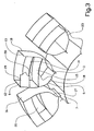
- FIG 3 and 4 is shown a first preferred embodiment of the component.
- Each of a plurality of essentially U-shaped elements 6, 17, 23 are connected to an inner ring element 7 and are placed adjacent to one another in the circumferential direction of the component.
- the one side member of the U-shaped element 6 forms a second wall part 9 and its other side member forms a further second wall part 10.
- the base of the U-shaped element 6 is connected to the inner ring element 7 by a rib 11, which extends in the intended axial direction of the component.
- the ends 12, 13 of the two side members are later connected to an outer ring element 8, see figure 4.
- Each of the two second wall parts 9, 10 thus extend essentially in the radial and axial direction of the component.
- the U-shaped element can be made, for example, by curving or bending a plate or a sheet into the desired shape.
- first wall parts 14, 15 are placed such that they extend in the circumferential direction of the component and at various distances apart in the radial direction between the two second wall parts 9, 10. More precisely, the two first wall parts 14, 15 are placed such that they bear with their end edges against the flat side of the second wall parts 9, 10. The end edges of the first wall parts 14, 15 are then laser-welded to the second wall parts 9, 10 from an, in the circumferential direction, opposite side of the second wall part 9, 10 in relation to the first wall part 14, 15. The laser-welding is realized in such a way that the joined-together portions of the wall parts 9, 10, 14, 15 form a T-shaped joint, see figure 2.
- the first wall part 15 which limits a gas duct 20 inwardly in the radial direction forms an intermediate portion of a plate-shaped member.
- This plate-shaped member has a shape corresponding to the space between the second, radial wall parts 9, 10 between these, see figure 3.
- the plate-shaped member has a U-shaped cross section and is constituted, for example, by a bent, or folded sheet.
- the side or plate portions 18 of the plate-shaped member have a shape and size corresponding to the space between the second wall parts 9, 10.
- the side portions of the plate-shaped member are also connected to the second wall parts 9, 10, expediently by laser-welding.
- the first wall part 14 which limits the gas duct 20 outwardly in the radial direction forms an intermediate portion of a further plate-shaped member.
- This plate-shaped member has a shape corresponding to the space between the second, radial wall parts 9, 10 between these, see figure 3.
- the plate-shaped member also has a U-shaped cross section and is constituted, for example, by a bent, or folded sheet, or by a tube or other profile.
- the side or plate portions 19 of the plate-shaped member have a shape and size corresponding to the space between the second wall parts 9, 10.
- the side portions of the plate-shaped member, too, are connected to the second wall parts 9, 10, expediently by laser-welding.
- Each of the side members of the U-shaped element 6 are connected to a side member 16 of an, in the circumferential direction, adjoining U-shaped element 17 in such a way that gas cannot flow between the side members, see figure 4.
- the mutually connected wall parts 9, 16 together form means for guidance of a gas flow and/or transmission of load in the radial direction during operation of the component.
- the adjoining wall parts 9, 16 are connected in figure 4 by a front and a rear cover wall 24, which thus enclose a space between the wall parts.
- These cover walls 24 are aerodynamically configured and have, in this case, a pointed shape so as to offer as little flow resistance as possible.
- This connection can be produced, for example, by welding.
- the two connected side members together form a blade, vane, stay or strut for guidance of a gas flow and/or transmission of load.
- the two wall parts of the U-shaped element which are spaced apart in the circumferential direction form two different blades or stays for guidance of a gas flow and/or transmission of load.
- FIG 4 is shown a schematic projection of a stator or rotor component 21 constructed according to the technique described above and illustrated in figure 3.
- the component 21 has an essentially circular cross-sectional shape and the ducts 20 for conduction of the gas flow extend in the axial direction between the inner ring, formed by the ring elements 7, and the outer ring 8.
- FIG 5 is illustrated a second embodiment of the stator component 23.
- a basic difference relative to the first embodiment is that the two spaced apart second wall parts 109, 110 do not form part of a U-shaped element but constitute separate units. All the wall parts 109, 110 in the component are first connected to a continuous inner ring 107. The first wall parts 114, 115 are connected to the second wall parts 109, 110 in the same manner as described above for the first embodiment. An outer ring 108 is then arranged around the wall parts 109, 110 and connected thereto.
- the materials which are used for the first and second wall parts 1, 2, 9, 10, 14, 15, 109, 110, 114 are constituted by weldable materials, such as stainless steel, for example of the type 347 or A286.
- weldable materials such as stainless steel, for example of the type 347 or A286.
- nickel-based alloys such as, for example, INCO600, INCO625, INCO718 and Hastaloy x, can be used.
- cobalt-based alloys for example, of the type HAYNES 188 and HAYNES 230, can be used.
- titanium alloys, such as Ti6-4, Ti6-2-4-2 and various types of aluminum alloys can be used. Combinations of different materials are also possible.
- a Nd:YAG-laser is preferably used, but also other types of welding arrangements, for example a CO 2 -laser, can be used according to the invention.
- a CO 2 -laser By precise coordination of the welding method, materials choice and wall parts dimensions, the T-shape in respect of a particular joint and a relatively gently rounded shape 22 of the inner angle between the second wall part and the first wall part are obtained with the laser-welding, see figure 2.
- the welding is expediently realized by means of a continuous weld.
- the rounded shape of the weld joints produces a high-strength construction and hence long working life for the component. This type of joining-together creates preconditions for a complete melting of the weld joint and fine transitions between the parts.
- the wall part has the shape of a plate.
- plate-shape is meant that the wall parts have two parallel side faces at a relatively short distance apart.
- ring element used above in the description is meant a continuously annular member, a substantially annular member interrupted in the circumferential direction, or a part which, together with other like parts, is intended to form an annular member.
- ring is meant a circumferential, band-shaped, preferably circular part, which spreads like a plate in the axial direction.
- the mutually connected second wall parts form the shape of a blade, for example, having an airfoil shape in cross section.
- a blade shape is utilized when the component is used in specific stator applications.
- the first wall part is not limited to just rounded or curved cross-sectional shape, but rather, for example, a square cross-sectional shape, that is to say made up of essentially straight portions of different direction, are also included.
- the wall parts extend in a certain direction with respect to the component is meant that at least one component of the extent of the wall part lies in this direction.
- the wall part extends substantially in this direction.
- the wall part in question extends in a plane parallel with said direction.
- the stator component can, for example, form an inlet part, an intermediate housing, a turbine-exhaust housing, that is to say a concluding housing part, or a part of this for a gas turbine. Its primary function is in this case to act as a bearing fastening, for the transmission of loads, and to provide a duct for gases.
- a wall part is placed such that it extends in the intended radial direction of the component is meant both that the wall part is placed directly in a structure in the radial direction of the component and that the wall part is first mounted in a section and that a plurality of such sections are then mutually connected in the circumferential direction so that the wall part ends up in said radial direction.
- connection of a wall part extending in the radial direction to another wall part extending in the radial direction can further be effected differently than arranging a cover plate between these.
- the wall parts can be arranged relatively close together and connected by the application of material, by welding, etc.
- the cover plates can be fixed in a number of different of ways, such as riveting and gluing.
- each comprising a first and a second wall part, and which sections each in cross section form the sector of a circle.
- the sections are then connected in the intended circumferential direction of the component to form the stator or rotor component.
- the second wall part is arranged in the intended radial direction of the component and the first wall part in the intended circumferential direction of the component.
Landscapes
- Engineering & Computer Science (AREA)
- Physics & Mathematics (AREA)
- Optics & Photonics (AREA)
- Mechanical Engineering (AREA)
- Plasma & Fusion (AREA)
- General Engineering & Computer Science (AREA)
- Laser Beam Processing (AREA)
- Iron Core Of Rotating Electric Machines (AREA)
- Manufacture Of Motors, Generators (AREA)
- Structures Of Non-Positive Displacement Pumps (AREA)
- Motor Or Generator Frames (AREA)
Claims (15)
- Verfahren zur Herstellung eines Stator- oder Rotorbauelements (21), das während des Betriebs einen Gasstrom leiten soll, wobei- das Bauelement (21) im wesentlichen eine Kreisquerschnittsform und eine Vielzahl von Kanälen (20) zum Leiten des Gasstroms aufweist, die sich in Axialrichtung zwischen einem inneren und einem äußeren Ring erstrecken,- ein erstes Wandteil (1, 14, 15, 114), das mit seinem einen Rand (3) gegen die flache Seite (4) eines zweiten Wandteils (4, 9, 109) drückend angeordnet wird,- der Rand des ersten Wandteils dann mit dem zweiten Wandteil von einer bezogen auf das erste Wandteil gegenüberliegenden Seite des zweiten Wandteils so laserverschweißt wird, dass die miteinander verbundenen Abschnitte der Wandteile eine T-förmige Verbindung (5) bilden, und- bei dem Verfahren das zweite Wandteil (4, 9, 109) so positioniert wird, dass es sich in einer radialen Richtung des Bauelements (21) erstreckt, und dass sich das erste Wandteil (1, 14, 15, 114) in einer Umfangs- und Axialrichtung des Bauelements (21) so erstreckt, dass das erste Wandteil (1, 14, 15, 114), das sich in der Umfangsrichtung erstreckt, so angeordnet wird, dass es einen der Gaskanäle (20) in der Radialrichtung begrenzt.
- Verfahren nach Anspruch 1, dadurch gekennzeichnet, dass das erste Wandteil (1, 14, 15, 114) im wesentlichen senkrecht zu der flachen Seite des zweiten Wandteils (4, 9, 109) angeordnet wird.
- Verfahren nach Anspruch 1 oder 2, dadurch gekennzeichnet, dass das zweite Wandteil (4, 9, 109) so angeordnet wird, dass es sich auch in der vorgesehenen Axialrichtung des Bauelements erstreckt.
- Verfahren nach einem der vorhergehenden Ansprüche, dadurch gekennzeichnet, dass das zweite Wandteil (4, 9, 109), das sich in der Radialrichtung erstreckt, so angeordnet wird, dass es einen Gaskanal (20) in der Umfangsrichtung des Bauelements begrenzt.
- Verfahren nach einem der vorhergehenden Ansprüche, dadurch gekennzeichnet, dass das zweite Wandteil (4, 9, 109) so angeordnet wird, dass es eine im wesentlichen radiale Aufweitung zum Führen des Gasstroms und/oder zur Lastübertragung während des Einsatzes des Bauteils hat.
- Verfahren nach einem der vorhergehenden Ansprüche, dadurch gekennzeichnet, dass das erste Wandteil (1, 14, 15, 114) eine Form hat, die sich im wesentlichen in der Umfangsrichtung krümmt.
- Verfahren nach einem der vorhergehenden Ansprüche, dadurch gekennzeichnet, dass das erste Wandteil (14, 15) mit einem zweiten Rand, der dem erstgenannten Rand gegenüberliegt, gegen die flache Seite eines weiteren zweiten Wandteils (10, 110) drückend angeordnet wird, das in der Umfangsrichtung in einer Entfernung von dem erstgenannten zweiten Wandteil (9) angeordnet und damit verbunden wird.
- Verfahren nach Anspruch 7, dadurch gekennzeichnet, dass der Rand des ersten Wandteils (14, 15, 114) mit diesem weiteren zweiten Wandteil (10, 110) in der Umfangsrichtung von einer bezogen auf das erste Wandteil gegenüberliegenden Seite des zweiten Wandteils aus auch so laserverschweißt wird, dass die miteinander verbundenen Abschnitte der Wandteile eine T-förmige Verbindung (5) bilden.
- Verfahren nach Anspruch 7 oder 8, dadurch gekennzeichnet, dass die beiden Wandteile (9, 10, 109, 110), die in der Umfangsrichtung beabstandet sind, wenigstens einen Teil von zwei verschiedenen Schaufeln oder Stützen zum Führen eines Gasstroms und/oder zur Lastübertragung bilden.
- Verfahren nach einem der Ansprüche 7 bis 9, dadurch gekennzeichnet, dass die beiden zweiten Wandteile (9, 10) von einem einzigen im wesentlichen U-förmigen Element (6) gebildet werden.
- Verfahren nach einem der vorhergehenden Ansprüche, dadurch gekennzeichnet, dass das erste und das zweite Wandteil (9, 10, 14, 15) zwischen einem in der Radialrichtung inneren und äußeren Ringelement (7, 8) angeordnet werden.
- Verfahren nach Anspruch 11, dadurch gekennzeichnet, dass das zweite Wandteil (9, 10) mit wenigstens einem der Ringelemente (7, 8) durch Laserverschweißen in der Radialrichtung von einer bezogen auf das zweite Wandteil gegenüberliegenden Seite des Ringelements aus so verbunden wird, dass die miteinander verbundenen Teile eine T-förmige Verbindung (5) bilden.
- Verfahren nach Anspruch 10 und entweder Anspruch 11 oder 12, dadurch gekennzeichnet, dass das U-förmige Element (6) vor dem Laserverschweißen der Wandteile zwischen dem inneren Ringelement (7) und dem äußeren Ringelement (8) angeordnet wird.
- Verfahren nach einem der vorhergehenden Ansprüche, dadurch gekennzeichnet, dass das Stator- oder Rotorbauelement (21, 23) für eine Gasturbine vorgesehen wird.
- Verfahren nach einem der vorhergehenden Ansprüche, dadurch gekennzeichnet, dass das Stator- oder Rotorbauelement (21, 23) für ein Strahltriebwerk vorgesehen wird.
Applications Claiming Priority (5)
| Application Number | Priority Date | Filing Date | Title |
|---|---|---|---|
| US40294602P | 2002-08-14 | 2002-08-14 | |
| SE0202422 | 2002-08-14 | ||
| US402946P | 2002-08-14 | ||
| SE0202422A SE525168C2 (sv) | 2002-08-14 | 2002-08-14 | Förfarande för framställning av en stator- eller rotorkomponent |
| PCT/SE2003/001145 WO2004016911A1 (en) | 2002-08-14 | 2003-06-30 | Method for manufacturing a stator or rotor component |
Publications (2)
| Publication Number | Publication Date |
|---|---|
| EP1540141A1 EP1540141A1 (de) | 2005-06-15 |
| EP1540141B1 true EP1540141B1 (de) | 2007-05-09 |
Family
ID=31890630
Family Applications (1)
| Application Number | Title | Priority Date | Filing Date |
|---|---|---|---|
| EP03733815A Expired - Lifetime EP1540141B1 (de) | 2002-08-14 | 2003-06-30 | Verfahren zur herstellung eines stator- oder rotorteils |
Country Status (9)
| Country | Link |
|---|---|
| US (1) | US20050246894A1 (de) |
| EP (1) | EP1540141B1 (de) |
| JP (1) | JP4481823B2 (de) |
| AT (1) | ATE362037T1 (de) |
| AU (1) | AU2003242170A1 (de) |
| DE (1) | DE60313782T2 (de) |
| ES (1) | ES2285131T3 (de) |
| RU (1) | RU2331778C2 (de) |
| WO (1) | WO2004016911A1 (de) |
Families Citing this family (15)
| Publication number | Priority date | Publication date | Assignee | Title |
|---|---|---|---|---|
| JP5118568B2 (ja) * | 2008-07-22 | 2013-01-16 | 株式会社日立製作所 | ガスタービンの排気ディフューザ |
| EP2379276A4 (de) * | 2008-12-19 | 2012-06-27 | Volvo Aero Corp | Speicher für eine statorkomponente, statorkomponente und verfahren zur herstellung einer statorkomponente |
| CH703309A1 (de) | 2010-06-10 | 2011-12-15 | Alstom Technology Ltd | Abgasgehäuse für eine gasturbine sowie verfahren zum herstellen eines solchen abgasgehäuses. |
| NL2009446A (en) | 2011-10-12 | 2013-04-15 | Asml Netherlands Bv | Radiation beam welding method, body and lithographic apparatus. |
| US9765648B2 (en) | 2011-12-08 | 2017-09-19 | Gkn Aerospace Sweden Ab | Gas turbine engine component |
| EP2795067B1 (de) | 2011-12-20 | 2019-03-13 | GKN Aerospace Sweden AB | Verfahren zur herstellung eines gasturbinenmotorbauteils |
| JP5946542B2 (ja) | 2011-12-22 | 2016-07-06 | ゲーコーエヌ エアロスペース スウェーデン アーベー | ガスタービンエンジンコンポーネント |
| JP5946543B2 (ja) * | 2011-12-23 | 2016-07-06 | ゲーコーエヌ エアロスペース スウェーデン アーベー | ガスタービンエンジンの支持構造物 |
| EP2795071B1 (de) | 2011-12-23 | 2017-02-01 | GKN Aerospace Sweden AB | Gasturbinenmotorkomponente |
| RU2494849C1 (ru) * | 2012-04-18 | 2013-10-10 | Открытое акционерное общество "Научно-производственное объединение "Сатурн" | Способ изготовления направляющего аппарата |
| TWI584905B (zh) * | 2012-07-27 | 2017-06-01 | 鴻準精密工業股份有限公司 | 風扇輪轂之製造方法 |
| RU2653396C1 (ru) * | 2016-12-19 | 2018-05-08 | Публичное акционерное общество "Региональный инжиниринговый центр промышленных лазерных технологий "КАИ-Лазер" | Способ изготовления тавровой балки лазерным лучом |
| RU2697545C1 (ru) * | 2018-08-17 | 2019-08-15 | Акционерное общество "Центр технологии судостроения и судоремонта" (АО "ЦТСС") | Способ лазерно-дуговой сварки угловых швов тавровых соединений |
| CN112638570B (zh) * | 2018-08-30 | 2023-07-07 | Ipg光子公司 | 背面焊接系统和方法 |
| JP7344558B2 (ja) * | 2020-02-25 | 2023-09-14 | デルタ工業株式会社 | レーザ溶接方法およびレーザ溶接装置 |
Family Cites Families (13)
| Publication number | Priority date | Publication date | Assignee | Title |
|---|---|---|---|---|
| US1641745A (en) * | 1924-04-17 | 1927-09-06 | Allis Chalmers Mfg Co | Method of uniting blades |
| US1833754A (en) * | 1930-08-22 | 1931-11-24 | Gen Electric | Vibration damping by impact |
| US2347034A (en) * | 1942-03-28 | 1944-04-18 | Gen Electric | Turbine bucket wheel and the like |
| US3451654A (en) * | 1967-08-25 | 1969-06-24 | Gen Motors Corp | Blade vibration damping |
| US3837761A (en) * | 1971-08-20 | 1974-09-24 | Westinghouse Electric Corp | Guide vanes for supersonic turbine blades |
| US3909157A (en) * | 1972-01-27 | 1975-09-30 | Chromalloy American Corp | Turbine nozzle-vane construction |
| US4868365A (en) * | 1988-06-06 | 1989-09-19 | Ford Motor Company | Method for welding torque converter blades to a housing using a laser welding beam |
| IL92428A (en) * | 1989-02-08 | 1992-12-01 | Gen Electric | Fabrication of components by layered deposition |
| RU2009378C1 (ru) * | 1992-01-08 | 1994-03-15 | Игорь Захарович Сазонов | Рабочее колесо центробежного вентилятора |
| FR2705603B1 (fr) * | 1993-05-25 | 1995-06-30 | Snecma | Procédé de soudage laser d'un assemblage de deux pièces métalliques. |
| DE19844035C1 (de) * | 1998-09-25 | 1999-11-25 | Daimler Chrysler Aerospace | Schalenbauteil für ein Flugzeug und Verfahren zur Herstellung |
| SE512942C2 (sv) * | 1998-10-02 | 2000-06-12 | Volvo Aero Corp | Förfarande för tillverkning av utloppsmunstycken för raketmotorer |
| JP3106130B1 (ja) * | 1999-07-23 | 2000-11-06 | 株式会社東芝 | タービンノズルの製造方法 |
-
2003
- 2003-06-30 RU RU2005107321/06A patent/RU2331778C2/ru not_active IP Right Cessation
- 2003-06-30 ES ES03733815T patent/ES2285131T3/es not_active Expired - Lifetime
- 2003-06-30 AT AT03733815T patent/ATE362037T1/de not_active IP Right Cessation
- 2003-06-30 AU AU2003242170A patent/AU2003242170A1/en not_active Abandoned
- 2003-06-30 EP EP03733815A patent/EP1540141B1/de not_active Expired - Lifetime
- 2003-06-30 JP JP2004528985A patent/JP4481823B2/ja not_active Expired - Fee Related
- 2003-06-30 WO PCT/SE2003/001145 patent/WO2004016911A1/en not_active Ceased
- 2003-06-30 DE DE60313782T patent/DE60313782T2/de not_active Expired - Lifetime
-
2005
- 2005-02-14 US US10/906,324 patent/US20050246894A1/en not_active Abandoned
Also Published As
| Publication number | Publication date |
|---|---|
| DE60313782D1 (de) | 2007-06-21 |
| EP1540141A1 (de) | 2005-06-15 |
| JP2005535826A (ja) | 2005-11-24 |
| RU2005107321A (ru) | 2006-04-20 |
| ES2285131T3 (es) | 2007-11-16 |
| JP4481823B2 (ja) | 2010-06-16 |
| ATE362037T1 (de) | 2007-06-15 |
| AU2003242170A1 (en) | 2004-03-03 |
| RU2331778C2 (ru) | 2008-08-20 |
| WO2004016911A1 (en) | 2004-02-26 |
| US20050246894A1 (en) | 2005-11-10 |
| DE60313782T2 (de) | 2008-01-24 |
Similar Documents
| Publication | Publication Date | Title |
|---|---|---|
| US7614150B2 (en) | Method for manufacturing a stator or rotor component | |
| US7200933B2 (en) | Method for manufacturing a stator component | |
| US7520055B2 (en) | Method for manufacturing a stator or rotor component | |
| EP1540141B1 (de) | Verfahren zur herstellung eines stator- oder rotorteils | |
| CA2701405C (en) | Structural reinforcement strut for gas turbine case | |
| CA2809987C (en) | Structural case for aircraft gas turbine engine | |
| US8469661B2 (en) | Fabricated gas turbine vane ring | |
| EP2187062B1 (de) | Montageverfahren für ein leitschaufelringsegment, und leitschaufelringsegment | |
| JP2006520874A (ja) | 静翼構成要素の製造方法 | |
| EP1534934B1 (de) | Verfahren zur herstellung einer statorkomponente | |
| US20050044708A1 (en) | Method for manufacturing a hollow blade for a stator or rotor component | |
| EP2309099B1 (de) | Verbindungskanal | |
| EP3279434A1 (de) | Luftmessungsleitteilanordnung | |
| US20110268575A1 (en) | Spoke for a stator component, stator component and method for manufacturing a stator component | |
| WO2025223726A1 (en) | Mount arrangement | |
| SE525168C2 (sv) | Förfarande för framställning av en stator- eller rotorkomponent |
Legal Events
| Date | Code | Title | Description |
|---|---|---|---|
| PUAI | Public reference made under article 153(3) epc to a published international application that has entered the european phase |
Free format text: ORIGINAL CODE: 0009012 |
|
| 17P | Request for examination filed |
Effective date: 20050314 |
|
| AK | Designated contracting states |
Kind code of ref document: A1 Designated state(s): AT BE BG CH CY CZ DE DK EE ES FI FR GB GR HU IE IT LI LU MC NL PT RO SE SI SK TR |
|
| AX | Request for extension of the european patent |
Extension state: AL LT LV MK |
|
| DAX | Request for extension of the european patent (deleted) | ||
| GRAP | Despatch of communication of intention to grant a patent |
Free format text: ORIGINAL CODE: EPIDOSNIGR1 |
|
| GRAS | Grant fee paid |
Free format text: ORIGINAL CODE: EPIDOSNIGR3 |
|
| GRAA | (expected) grant |
Free format text: ORIGINAL CODE: 0009210 |
|
| AK | Designated contracting states |
Kind code of ref document: B1 Designated state(s): AT BE BG CH CY CZ DE DK EE ES FI FR GB GR HU IE IT LI LU MC NL PT RO SE SI SK TR |
|
| PG25 | Lapsed in a contracting state [announced via postgrant information from national office to epo] |
Ref country code: LI Free format text: LAPSE BECAUSE OF FAILURE TO SUBMIT A TRANSLATION OF THE DESCRIPTION OR TO PAY THE FEE WITHIN THE PRESCRIBED TIME-LIMIT Effective date: 20070509 Ref country code: CH Free format text: LAPSE BECAUSE OF FAILURE TO SUBMIT A TRANSLATION OF THE DESCRIPTION OR TO PAY THE FEE WITHIN THE PRESCRIBED TIME-LIMIT Effective date: 20070509 Ref country code: FI Free format text: LAPSE BECAUSE OF FAILURE TO SUBMIT A TRANSLATION OF THE DESCRIPTION OR TO PAY THE FEE WITHIN THE PRESCRIBED TIME-LIMIT Effective date: 20070509 |
|
| REG | Reference to a national code |
Ref country code: GB Ref legal event code: FG4D |
|
| REG | Reference to a national code |
Ref country code: CH Ref legal event code: EP |
|
| REG | Reference to a national code |
Ref country code: IE Ref legal event code: FG4D |
|
| REF | Corresponds to: |
Ref document number: 60313782 Country of ref document: DE Date of ref document: 20070621 Kind code of ref document: P |
|
| PG25 | Lapsed in a contracting state [announced via postgrant information from national office to epo] |
Ref country code: SE Free format text: LAPSE BECAUSE OF FAILURE TO SUBMIT A TRANSLATION OF THE DESCRIPTION OR TO PAY THE FEE WITHIN THE PRESCRIBED TIME-LIMIT Effective date: 20070809 |
|
| ET | Fr: translation filed | ||
| NLV1 | Nl: lapsed or annulled due to failure to fulfill the requirements of art. 29p and 29m of the patents act | ||
| REG | Reference to a national code |
Ref country code: CH Ref legal event code: PL |
|
| REG | Reference to a national code |
Ref country code: ES Ref legal event code: FG2A Ref document number: 2285131 Country of ref document: ES Kind code of ref document: T3 |
|
| PG25 | Lapsed in a contracting state [announced via postgrant information from national office to epo] |
Ref country code: AT Free format text: LAPSE BECAUSE OF FAILURE TO SUBMIT A TRANSLATION OF THE DESCRIPTION OR TO PAY THE FEE WITHIN THE PRESCRIBED TIME-LIMIT Effective date: 20070509 |
|
| PG25 | Lapsed in a contracting state [announced via postgrant information from national office to epo] |
Ref country code: BE Free format text: LAPSE BECAUSE OF FAILURE TO SUBMIT A TRANSLATION OF THE DESCRIPTION OR TO PAY THE FEE WITHIN THE PRESCRIBED TIME-LIMIT Effective date: 20070509 |
|
| PG25 | Lapsed in a contracting state [announced via postgrant information from national office to epo] |
Ref country code: MC Free format text: LAPSE BECAUSE OF NON-PAYMENT OF DUE FEES Effective date: 20070630 Ref country code: DK Free format text: LAPSE BECAUSE OF FAILURE TO SUBMIT A TRANSLATION OF THE DESCRIPTION OR TO PAY THE FEE WITHIN THE PRESCRIBED TIME-LIMIT Effective date: 20070509 Ref country code: NL Free format text: LAPSE BECAUSE OF FAILURE TO SUBMIT A TRANSLATION OF THE DESCRIPTION OR TO PAY THE FEE WITHIN THE PRESCRIBED TIME-LIMIT Effective date: 20070509 Ref country code: CZ Free format text: LAPSE BECAUSE OF FAILURE TO SUBMIT A TRANSLATION OF THE DESCRIPTION OR TO PAY THE FEE WITHIN THE PRESCRIBED TIME-LIMIT Effective date: 20070509 Ref country code: BG Free format text: LAPSE BECAUSE OF FAILURE TO SUBMIT A TRANSLATION OF THE DESCRIPTION OR TO PAY THE FEE WITHIN THE PRESCRIBED TIME-LIMIT Effective date: 20070809 Ref country code: PT Free format text: LAPSE BECAUSE OF FAILURE TO SUBMIT A TRANSLATION OF THE DESCRIPTION OR TO PAY THE FEE WITHIN THE PRESCRIBED TIME-LIMIT Effective date: 20071009 Ref country code: SI Free format text: LAPSE BECAUSE OF FAILURE TO SUBMIT A TRANSLATION OF THE DESCRIPTION OR TO PAY THE FEE WITHIN THE PRESCRIBED TIME-LIMIT Effective date: 20070509 |
|
| PG25 | Lapsed in a contracting state [announced via postgrant information from national office to epo] |
Ref country code: SK Free format text: LAPSE BECAUSE OF FAILURE TO SUBMIT A TRANSLATION OF THE DESCRIPTION OR TO PAY THE FEE WITHIN THE PRESCRIBED TIME-LIMIT Effective date: 20070509 |
|
| PLBE | No opposition filed within time limit |
Free format text: ORIGINAL CODE: 0009261 |
|
| STAA | Information on the status of an ep patent application or granted ep patent |
Free format text: STATUS: NO OPPOSITION FILED WITHIN TIME LIMIT |
|
| 26N | No opposition filed |
Effective date: 20080212 |
|
| PG25 | Lapsed in a contracting state [announced via postgrant information from national office to epo] |
Ref country code: GR Free format text: LAPSE BECAUSE OF FAILURE TO SUBMIT A TRANSLATION OF THE DESCRIPTION OR TO PAY THE FEE WITHIN THE PRESCRIBED TIME-LIMIT Effective date: 20070810 |
|
| PG25 | Lapsed in a contracting state [announced via postgrant information from national office to epo] |
Ref country code: RO Free format text: LAPSE BECAUSE OF FAILURE TO SUBMIT A TRANSLATION OF THE DESCRIPTION OR TO PAY THE FEE WITHIN THE PRESCRIBED TIME-LIMIT Effective date: 20070509 |
|
| PG25 | Lapsed in a contracting state [announced via postgrant information from national office to epo] |
Ref country code: IE Free format text: LAPSE BECAUSE OF NON-PAYMENT OF DUE FEES Effective date: 20070702 |
|
| PG25 | Lapsed in a contracting state [announced via postgrant information from national office to epo] |
Ref country code: EE Free format text: LAPSE BECAUSE OF FAILURE TO SUBMIT A TRANSLATION OF THE DESCRIPTION OR TO PAY THE FEE WITHIN THE PRESCRIBED TIME-LIMIT Effective date: 20070509 |
|
| PG25 | Lapsed in a contracting state [announced via postgrant information from national office to epo] |
Ref country code: CY Free format text: LAPSE BECAUSE OF FAILURE TO SUBMIT A TRANSLATION OF THE DESCRIPTION OR TO PAY THE FEE WITHIN THE PRESCRIBED TIME-LIMIT Effective date: 20070509 |
|
| PG25 | Lapsed in a contracting state [announced via postgrant information from national office to epo] |
Ref country code: LU Free format text: LAPSE BECAUSE OF NON-PAYMENT OF DUE FEES Effective date: 20070630 |
|
| PG25 | Lapsed in a contracting state [announced via postgrant information from national office to epo] |
Ref country code: HU Free format text: LAPSE BECAUSE OF FAILURE TO SUBMIT A TRANSLATION OF THE DESCRIPTION OR TO PAY THE FEE WITHIN THE PRESCRIBED TIME-LIMIT Effective date: 20071110 Ref country code: TR Free format text: LAPSE BECAUSE OF FAILURE TO SUBMIT A TRANSLATION OF THE DESCRIPTION OR TO PAY THE FEE WITHIN THE PRESCRIBED TIME-LIMIT Effective date: 20070509 |
|
| PGFP | Annual fee paid to national office [announced via postgrant information from national office to epo] |
Ref country code: DE Payment date: 20120627 Year of fee payment: 10 |
|
| PGFP | Annual fee paid to national office [announced via postgrant information from national office to epo] |
Ref country code: FR Payment date: 20120619 Year of fee payment: 10 Ref country code: GB Payment date: 20120627 Year of fee payment: 10 |
|
| PGFP | Annual fee paid to national office [announced via postgrant information from national office to epo] |
Ref country code: IT Payment date: 20120621 Year of fee payment: 10 |
|
| PGFP | Annual fee paid to national office [announced via postgrant information from national office to epo] |
Ref country code: ES Payment date: 20120726 Year of fee payment: 10 |
|
| GBPC | Gb: european patent ceased through non-payment of renewal fee |
Effective date: 20130630 |
|
| REG | Reference to a national code |
Ref country code: DE Ref legal event code: R119 Ref document number: 60313782 Country of ref document: DE Effective date: 20140101 |
|
| REG | Reference to a national code |
Ref country code: FR Ref legal event code: ST Effective date: 20140228 |
|
| PG25 | Lapsed in a contracting state [announced via postgrant information from national office to epo] |
Ref country code: GB Free format text: LAPSE BECAUSE OF NON-PAYMENT OF DUE FEES Effective date: 20130630 Ref country code: DE Free format text: LAPSE BECAUSE OF NON-PAYMENT OF DUE FEES Effective date: 20140101 |
|
| PG25 | Lapsed in a contracting state [announced via postgrant information from national office to epo] |
Ref country code: IT Free format text: LAPSE BECAUSE OF NON-PAYMENT OF DUE FEES Effective date: 20130630 Ref country code: FR Free format text: LAPSE BECAUSE OF NON-PAYMENT OF DUE FEES Effective date: 20130701 |
|
| REG | Reference to a national code |
Ref country code: ES Ref legal event code: FD2A Effective date: 20140707 |
|
| PG25 | Lapsed in a contracting state [announced via postgrant information from national office to epo] |
Ref country code: ES Free format text: LAPSE BECAUSE OF NON-PAYMENT OF DUE FEES Effective date: 20130701 |