EP1541297A1 - Vorrichtung zum Trennen einer Materialbahn - Google Patents
Vorrichtung zum Trennen einer Materialbahn Download PDFInfo
- Publication number
- EP1541297A1 EP1541297A1 EP04106171A EP04106171A EP1541297A1 EP 1541297 A1 EP1541297 A1 EP 1541297A1 EP 04106171 A EP04106171 A EP 04106171A EP 04106171 A EP04106171 A EP 04106171A EP 1541297 A1 EP1541297 A1 EP 1541297A1
- Authority
- EP
- European Patent Office
- Prior art keywords
- electromagnetic
- drive
- elements
- phase
- separating
- Prior art date
- Legal status (The legal status is an assumption and is not a legal conclusion. Google has not performed a legal analysis and makes no representation as to the accuracy of the status listed.)
- Granted
Links
- 239000000463 material Substances 0.000 claims abstract description 26
- 230000005672 electromagnetic field Effects 0.000 claims description 20
- 239000003990 capacitor Substances 0.000 claims description 17
- 230000005284 excitation Effects 0.000 claims description 17
- 238000013016 damping Methods 0.000 claims description 9
- 230000008859 change Effects 0.000 claims description 7
- XEEYBQQBJWHFJM-UHFFFAOYSA-N Iron Chemical group [Fe] XEEYBQQBJWHFJM-UHFFFAOYSA-N 0.000 claims description 4
- 238000004891 communication Methods 0.000 claims description 2
- 238000000926 separation method Methods 0.000 description 12
- 230000001133 acceleration Effects 0.000 description 8
- 238000005520 cutting process Methods 0.000 description 7
- 230000000694 effects Effects 0.000 description 6
- 238000000034 method Methods 0.000 description 6
- 230000008569 process Effects 0.000 description 6
- 230000008901 benefit Effects 0.000 description 5
- 238000004146 energy storage Methods 0.000 description 5
- 230000002123 temporal effect Effects 0.000 description 3
- 230000004907 flux Effects 0.000 description 2
- 230000006698 induction Effects 0.000 description 2
- 238000004519 manufacturing process Methods 0.000 description 2
- 230000001360 synchronised effect Effects 0.000 description 2
- 230000008878 coupling Effects 0.000 description 1
- 238000010168 coupling process Methods 0.000 description 1
- 238000005859 coupling reaction Methods 0.000 description 1
- 238000007599 discharging Methods 0.000 description 1
- 230000002349 favourable effect Effects 0.000 description 1
- 238000002955 isolation Methods 0.000 description 1
- 230000007257 malfunction Effects 0.000 description 1
- 238000005192 partition Methods 0.000 description 1
- 230000002441 reversible effect Effects 0.000 description 1
- 230000007704 transition Effects 0.000 description 1
Images

Classifications
-
- B—PERFORMING OPERATIONS; TRANSPORTING
- B26—HAND CUTTING TOOLS; CUTTING; SEVERING
- B26D—CUTTING; DETAILS COMMON TO MACHINES FOR PERFORATING, PUNCHING, CUTTING-OUT, STAMPING-OUT OR SEVERING
- B26D5/00—Arrangements for operating and controlling machines or devices for cutting, cutting-out, stamping-out, punching, perforating, or severing by means other than cutting
- B26D5/08—Means for actuating the cutting member to effect the cut
- B26D5/086—Electric, magnetic, piezoelectric, electro-magnetic means
-
- B—PERFORMING OPERATIONS; TRANSPORTING
- B26—HAND CUTTING TOOLS; CUTTING; SEVERING
- B26D—CUTTING; DETAILS COMMON TO MACHINES FOR PERFORATING, PUNCHING, CUTTING-OUT, STAMPING-OUT OR SEVERING
- B26D1/00—Cutting through work characterised by the nature or movement of the cutting member or particular materials not otherwise provided for; Apparatus or machines therefor; Cutting members therefor
- B26D1/01—Cutting through work characterised by the nature or movement of the cutting member or particular materials not otherwise provided for; Apparatus or machines therefor; Cutting members therefor involving a cutting member which does not travel with the work
- B26D1/04—Cutting through work characterised by the nature or movement of the cutting member or particular materials not otherwise provided for; Apparatus or machines therefor; Cutting members therefor involving a cutting member which does not travel with the work having a linearly-movable cutting member
- B26D1/06—Cutting through work characterised by the nature or movement of the cutting member or particular materials not otherwise provided for; Apparatus or machines therefor; Cutting members therefor involving a cutting member which does not travel with the work having a linearly-movable cutting member wherein the cutting member reciprocates
- B26D1/08—Cutting through work characterised by the nature or movement of the cutting member or particular materials not otherwise provided for; Apparatus or machines therefor; Cutting members therefor involving a cutting member which does not travel with the work having a linearly-movable cutting member wherein the cutting member reciprocates of the guillotine type
- B26D1/085—Cutting through work characterised by the nature or movement of the cutting member or particular materials not otherwise provided for; Apparatus or machines therefor; Cutting members therefor involving a cutting member which does not travel with the work having a linearly-movable cutting member wherein the cutting member reciprocates of the guillotine type for thin material, e.g. for sheets, strips or the like
-
- B—PERFORMING OPERATIONS; TRANSPORTING
- B26—HAND CUTTING TOOLS; CUTTING; SEVERING
- B26D—CUTTING; DETAILS COMMON TO MACHINES FOR PERFORATING, PUNCHING, CUTTING-OUT, STAMPING-OUT OR SEVERING
- B26D5/00—Arrangements for operating and controlling machines or devices for cutting, cutting-out, stamping-out, punching, perforating, or severing by means other than cutting
- B26D5/02—Means for moving the cutting member into its operative position for cutting
- B26D5/06—Means for moving the cutting member into its operative position for cutting by electrical means
-
- B—PERFORMING OPERATIONS; TRANSPORTING
- B26—HAND CUTTING TOOLS; CUTTING; SEVERING
- B26D—CUTTING; DETAILS COMMON TO MACHINES FOR PERFORATING, PUNCHING, CUTTING-OUT, STAMPING-OUT OR SEVERING
- B26D5/00—Arrangements for operating and controlling machines or devices for cutting, cutting-out, stamping-out, punching, perforating, or severing by means other than cutting
- B26D5/08—Means for actuating the cutting member to effect the cut
Definitions
- the present invention relates to a device for separating a Material web arranged with a transverse to the direction of the web Separating element, which translationally in the direction of a drive the material web is movable.
- EP 1 025 307 B1 describes a web separation device in which to a movable piston in a piston chamber a separating blade is appropriate.
- the separating blade the piston and extend the piston chamber over the entire width of the web to be separated.
- a valve between the piston chamber and one of the pressure chambers acts Under and over pressures generated.
- the channels connect with different pressures, the air pressure rises below of the piston in a very short period of time, so that the piston performs a fast movement in the direction of the material web.
- the am Piston-mounted cutting blade is also in the direction of the web accelerates, beats the track and separates them at the desired Place off.
- EP 1 063 087 B1 discloses a device for cutting material webs known, in which by means of a compressed air cylinder, a cutting element is accelerated with a knife. With two three-way valves and a control unit will have an air pressure of about 4.8 bar on a first Side of the air cylinder predetermined. With a control unit is a Transition of the air cylinder from the non-cutting state to Controlled cutting process. It prevails in the air cylinder on one second side of the cylinder, a second pressure of about 6.2 bar. With Quick discharge valves become the second pressure to initiate the cutting process quickly to a value below the first predetermined pressure reduced. A connected to the compressed air cylinder and driven by this Cutting element separates the material web.
- the running speeds of, for example 2,000 m / min is due to the separation of the material web special requirements.
- the aim is the material web during operation without slowing down or stopping the Separate train. It is important that the separation process no damage the material web or even an influence on the manufacturing process causes. It is aimed at the separation process in Fractions of seconds.
- the invention is based on the object, a controllable device for separating webs of material, wherein the separating element experiencing a high acceleration.
- This object is characterized in the device of the type mentioned by solved that the drive is designed as an electromagnetic drive is, with the electromagnetic forces in the direction of movement of the separating element can be generated.
- the electromagnetic drive provides electromagnetic fields that are either repulsive or attractive Act.
- the electromagnetic fields cause repulsive or attractive forces used in the device according to the invention to accelerate the separator.
- electromagnetic Fields are very easy to control. This affects both their spatial Shape as well as its temporal changeability.
- the spatial form is by the nature of the arrangement of electromagnetic elements and whose geometry can be influenced.
- the temporal variability is through Current and voltage curves at the electrical connections of the electromagnetic Drive set.
- Another advantage of the electromagnetic Drive is that electromagnetic fields mechanically built inert, degraded and can be changed.
- An advantage of the device according to the invention is that the electromagnetic drive is performed at least single-phase. This means that both a single-phase and multi-phase design the device is possible. In a multi-phase design, for example can be three-phase, is also per phase a separator to disposal. These separators can be used synchronously, as well as used for repeated separation alternately in time become. With a synchronous separation of all installed separators Thus, for example, at least two track sections in one operation be separated. It is also conceivable that each Separating element is associated with a material web, so that, for example three webs can be separated simultaneously. At a not synchronized movement of the separating elements, for example any charging to provide the electromagnetic Energy that takes a certain time, alternately in the Dividing elements are made so that at least always one the available dividing elements can be used immediately.
- the drive has two electromagnetic elements per Phase, wherein at least one of the elements is movable.
- the repulsive forces or attractions between the two elements are caused by electromagnetic fields.
- the repulsive or attractive effect of the electromagnetic fields is used, to accelerate an element in the direction of the material web.
- the two electromagnetic Elements per phase formed by two electric coils Due to the presence of at least one coil can be an electromagnetic Field are generated.
- the electromagnetic field of the first Coil generates in the second coil an opposing field by induction effect. It thus repulsive or attractive forces act on the two electric coils.
- an electromagnetic element is the Phase formed as a short-circuited coil.
- a shorted one Coil is a simple element that is movably installed to function can be, because there are no leads on the coil. Existing supply lines would have to be carried along with a movement of the coil to a To prevent tearing of the supply lines. These precautions are included a shorted coil not necessary.
- electromagnetic fields are present across an iron core the two electromagnetic elements per phase coupled are. This has the advantage that the electromagnetic fields are effective can be used and scatters of fields are kept low can.
- the drive is connectable to an excitation device.
- the excitation device may be the electromagnetic elements of the drive provide energy so that electromagnetic fields can arise.
- Such an excitation device can, for example a voltage source having a frequency greater than zero, such as. an AC voltage source or a pulse generator.
- a pulse-shaped Current change can be generated.
- the acceleration of the electromagnetic Elements depends on the temporal change of the magnetic flux through the surface of the electromagnetic elements.
- a pulse-shaped Current change induced on an electromagnetic element in the second electromagnetic element a large flux change, so suddenly a force acts on the second electromagnetic element, which this electromagnetic element of the first electromagnetic Element away accelerated or to the first electromagnetic Accelerated element.
- the excitation device has at least one energy store, which has a Switching element per phase with at least one of the electromagnetic Elements of the drive of the phase is connectable.
- An energy storage can initially provide the electromagnetic energy and upon actuation of the switching element, this energy is passed on to the drive. In this way, the energy is ready, so that they immediately for the electromagnetic elements for accelerating the separating knife is available.
- the excitation device a capacitor on at least one of the two electromagnetic elements of the drive is connectable.
- the capacitor stores electrical energy that is pulsed during a discharge process delivered to a connected electromagnetic element can be, thus forms a pulse generator.
- the excitation device with a DC voltage source connectable.
- a DC voltage source For example, a capacitor can be charged directly, which in turn as energy storage to provide the electromagnetic Energy can be used for the drive.
- the excitation device with an AC voltage source connectable.
- AC voltage is the usual Form of the generally available energy supply.
- the alternating voltage can be single-phase or multi-phase available stand and a switching element per phase the electromagnetic Elements are supplied. If a DC voltage is required, then For example, with the help of diodes, the AC voltage can also be in be converted to a DC voltage. This can be used if a capacitor is to be charged as energy storage and no DC voltage is available.
- the AC voltage source per phase via a Transformer with at least one of the electromagnetic elements connect the drive.
- a transformer causes a galvanic decoupling between the input and output terminals of the transformer.
- the transformer only accept the function of galvanic isolation or also provide additional voltage and current at a desired level, which can be used for the electromagnetic drive.
- the excitation device is controllable. It can thus the acceleration process of the repulsive or attractive introduced electromagnetic elements at a selectable time become.
- the control unit may also contain electrical components that influence the time course of the potential change, e.g. electrical Resistors, electrical capacitors and spark gaps.
- electrical Resistors electrical Resistors
- electrical capacitors at the use of a capacitor as energy storage can this previously charged with, for example, an AC voltage source.
- rectifying elements such as. Diodes necessary.
- the discharging of the capacitor can be initiated for example by means of a switch.
- the at the Discharge power provided is determined by the capacitance of the capacitor established. With the help of electrical resistors in connection with the capacity of the capacitor is the time course of the discharge controllable.
- the separating element via a movable Guide element is in communication with the drive.
- the guide element With the help of the guide element will be the movement of the accelerated separator controlled and guided to a defined point of the web. With the guide element and the accuracy of the separation position is improved. It is also by using a guide element not necessary to install the drive directly on the material web.
- the movable elements of the device are with a damping element in connection. It can thus, for example the movement of the separating element, the guide element and the ejected Coil dampened after separating the material web and finally slowed down.
- the damping element Act When moving the movable elements in its initial position can also the damping element Act.
- the damping element is at least in the end regions the back and forth movements effectively.
- After separating the Material web is to get back the separating element in its starting position.
- the backward movement the separating element in its initial position is also from the damping element decelerating supported until the partition at his Starting position arrives and there remains unmoved until the next separation process is initiated.
- the drive is surrounded by an electromagnetic shield.
- an electromagnetic shield for example in the form of a metallic Sheathing or in the form of umbrellas in the supply lines of the Device, the electromagnetic compatibility is improved.
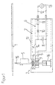
- Fig. 1 in the vicinity of the material web 1 is the electromagnetic drive 2 with two electromagnetic elements installed. These two Elements are realized in the form of electrical coils 3, 4, wherein the first coil 3 is stationary and the second coil 4 with a guide element 5 is movable. The second coil 4 is a short-circuited coil educated. The first coil 3 can at its terminals 6 to an excitation device 7 are connected.
- a capacitor 8 is provided for a pulse-shaped current change.
- the capacitor 8 is connected via a charging device 9, for example consists of a diode 10 and an electrical resistance 11, charged.
- a charging device 9 for example consists of a diode 10 and an electrical resistance 11, charged.
- a generator of an AC voltage 13 is connected.
- the Capacitor 8 can also be used any other charging device 9 For example, is a direct connection of a DC voltage source to the capacitor 8 possible.
- a switch 14 closed and the separation process of the web 1 initiated.
- the capacitor 8 discharges in a pulse shape and a current flows through the first coil 3.
- This current causes an electromagnetic field applied to the second coil 4, the the first coil 3 is arranged, is also present.
- the second Coil 4 builds a second electromagnetic due to the induction effect Field that opposes the first field. It arises between the two coils 3, 4 a repulsive force. Since the first coil 3 here is stationary, the second coil 4 is accelerated in the direction of the material web 1.
- the length of the separating element 15 has in this embodiment, the Width of the web 1, so that the separating element 15 through the Acceleration process hits the web 1 and this in one operation separates.
- the guide member 5 indicates the direction of movement of the separating element 15 before.
- the guide element 5 is on his the separator 15 opposite end with a Damping element 16 connected.
- the damping element 16 dampens both the movement of the accelerated elements, here the second coil 4, the guide member 5 and the separator 15, immediately after the separation of the web 1, as well as the movement of the elements in their starting position back.
- the electromagnetic drive 2 with the first coil 3 and the second Coil 4 and here also the capacitor 8 with charger 9 are wrapped with an electromagnetic shield 17, so that neither electromagnetic Fields of the drive surrounding equipment of web production still affect foreign electromagnetic fields erfi the proper Affect device.
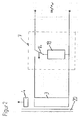
- One Energy storage 18, previously with a DC voltage source or a AC voltage source 13 connected by means of the switching element 14 has been, upon actuation of the switching element 14 electromagnetic Energy at the first electric coil 3 ready.
- the second Spool 4 is set in motion.
- the coupling of the electromagnetic Fields between the two electric coils 3, 4 is done via a Iron core 20.
- Fig. 3 illustrates a possible multi-phase arrangement Drive 2 with the electric coils 3, 4 via a three-phase connection L1, L2, L3 supplied.
- the three-phase connection L1, L2, L3 is via the switching elements 14th connectable to the electric coils 3.
- a transformer 19th This galvanically separates the drive 2 from the three-phase connection L1, L2, L3 and can also vary depending on the selected ratio voltage and Provide power at a desired height.
- the transformer 19 is here three-phase executed, also are instead three individual transformers 19 possible.
- the energy provided with it is over the Iron core 20 the first electric coil 3 to the second electrical Coils 4 transmit, characterized by the repulsive effect between the electric coils 3, 4 move away from the first coil 3 and thus initiate separation processes.
Landscapes
- Life Sciences & Earth Sciences (AREA)
- Forests & Forestry (AREA)
- Engineering & Computer Science (AREA)
- Mechanical Engineering (AREA)
- Registering, Tensioning, Guiding Webs, And Rollers Therefor (AREA)
- Portable Nailing Machines And Staplers (AREA)
- Processing And Handling Of Plastics And Other Materials For Molding In General (AREA)
- Elimination Of Static Electricity (AREA)
- Preliminary Treatment Of Fibers (AREA)
Abstract
Description
- Fig. 1
- eine schematische Darstellung der Erfi ndung,
- Fig. 2
- eine weitere Ausführungsform der Erfindung und
- Fig. 3
- ein Beispiel für eine mehrphasige Ausführung der Erfindung.
Claims (18)
- Vorrichtung zum Trennen einer Materialbahn mit einem quer zur Laufrichtung der Materialbahn angeordneten Trennelement, das durch einen Antrieb translatorisch in Richtung der Materialbahn bewegbar ist, dadurch gekennzeichnet, daß der Antrieb als elektromagnetischer Antrieb (2) ausgebildet ist, mit dem elektromagnetische Kräfte in Bewegungsrichtung des Trennelementes (15) erzeugbar sind.
- Vorrichtung nach Anspruch 1, dadurch gekennzeichnet, daß der elektromagnetische Antrieb (2) mindestens einphasig ausgeführt ist.
- Vorrichtung nach Anspruch 2, dadurch gekennzeichnet, daß der Antrieb (2) zwei elektromagnetische Elemente pro Phase aufweist, wobei mindestens eines der Elemente bewegbar ist.
- Vorrichtung nach Anspruch 3, dadurch gekennzeichnet, daß die beiden elektromagnetischen Elemente pro Phase durch zwei elektrische Spulen (3, 4) ausgebildet sind.
- Vorrichtung nach Anspruch 3 oder 4, dadurch gekennzeichnet, daß ein elektromagnetisches Element der Phase als kurzgeschlossene Spule (4) ausgebildet ist.
- Vorrichtung nach einem der Ansprüche 3 bis 5, dadurch geken n-zeichnet, daß elektromagnetische Felder über einen Eisenkern (20) zwischen den beiden elektromagnetischen Elementen (3, 4) pro Phase koppelbar sind.
- Vorrichtung nach einem der Ansprüche 2 bis 6, dadurch gekennzeichnet, daß der Antrieb (2) mit einer Anregungseinrichtung (7) verbindbar ist.
- Vorrichtung nach Anspruch 7, dadurch gekennzeichnet, daß mit der Anregungseinrichtung (7) eine impulsförmige Stromänderung erzeugbar ist.
- Vorrichtung nach Anspruch 8, dadurch gekennzeichnet, daß die Anregungseinrichtung (7) mindestens einen Energiespeicher (18) aufweist, der über ein Schaltelement (14) pro Phase mit mindestens einem der elektromagnetischen Elemente (3, 4) des Antriebs (2) der Phase verbindbar ist.
- Vorrichtung nach einem der Ansprüche 7 bis 9, dadurch geken n-zeichnet, daß die Anregungseinrichtung (7) einen Kondensator (8) aufweist, der mindestens mit einem der beiden elektromagnetischen Elemente (3, 4) des Antriebs (2) verbindbar ist.
- Vorrichtung nach einem der Ansprüche 7 bis 10, dadurch geken n-zeichnet, daß die Anregungseinrichtung (7) mit einer Gleichspannungsquelle verbindbar ist.
- Vorrichtung nach einem der Ansprüche 7 bis 10, dadurch geken n-zeichnet, daß die Anregungseinrichtung (7) mit einer Wechselspannungsquelle (13) verbindbar ist.
- Vorrichtung nach Anspruch 12, dadurch gekennzeichnet, daß die Wechselspannungsquelle (13) pro Phase über einen Transformator (19) mit mindestens einem der elektromagnetischen Elemente (3, 4) des Antriebs (2) verbindbar ist.
- Vorrichtung nach einem der Ansprüche 7 bis 13, dadurch geken n-zeichnet, daß die Anregungseinrichtung (7) steuerbar ist.
- Vorrichtung nach einem der Ansprüche 1 bis 14, dadurch geken n-zeichnet, daß das Trennelement (15) über ein bewegbares Führungselement (5) mit dem Antrieb (2) in Verbindung steht.
- Vorrichtung nach einem der Ansprüche 1 bis 15, dadurch geken n-zeichnet, daß die beweglichen Elemente der Vorrichtung mit einem Dämpfungselement (16) in Verbindung stehen.
- Vorrichtung nach Anspruch 16, dadurch gekennzeichnet, daß das Dämpfungselement (16) zumindest in den Endbereichen der Hinund Rückbewegungen wirksam ist.
- Vorrichtung nach einem der Ansprüche 1 bis 17, dadurch geken n-zeichnet, daß der Antrieb (2) von einem elektromagnetischen Schirm (17) umgeben ist.
Applications Claiming Priority (2)
| Application Number | Priority Date | Filing Date | Title |
|---|---|---|---|
| DE20319210U DE20319210U1 (de) | 2003-12-11 | 2003-12-11 | Vorrichtung zum Trennen einer Materialbahn |
| DE20319210U | 2003-12-11 |
Publications (2)
| Publication Number | Publication Date |
|---|---|
| EP1541297A1 true EP1541297A1 (de) | 2005-06-15 |
| EP1541297B1 EP1541297B1 (de) | 2007-01-24 |
Family
ID=31984824
Family Applications (1)
| Application Number | Title | Priority Date | Filing Date |
|---|---|---|---|
| EP04106171A Expired - Lifetime EP1541297B1 (de) | 2003-12-11 | 2004-11-30 | Vorrichtung zum Trennen einer Materialbahn |
Country Status (4)
| Country | Link |
|---|---|
| EP (1) | EP1541297B1 (de) |
| AT (1) | ATE352401T1 (de) |
| DE (2) | DE20319210U1 (de) |
| ES (1) | ES2281759T3 (de) |
Cited By (3)
| Publication number | Priority date | Publication date | Assignee | Title |
|---|---|---|---|---|
| CN105565056A (zh) * | 2015-12-10 | 2016-05-11 | 湖南文理学院 | 一种纺织机用滚动式电磁裁剪装置 |
| CN105798203A (zh) * | 2016-03-15 | 2016-07-27 | 南京伶机宜动驱动技术有限公司 | 集成旋切装置 |
| CN106141289A (zh) * | 2015-03-16 | 2016-11-23 | 江苏雨燕模塑有限公司 | 汽车配件电磁感应截断机 |
Citations (7)
| Publication number | Priority date | Publication date | Assignee | Title |
|---|---|---|---|---|
| SU482287A1 (ru) * | 1972-10-17 | 1975-08-30 | Электромагнитные ножницы | |
| US5079980A (en) * | 1990-09-18 | 1992-01-14 | Markem Corporation | Method and apparatus for accumulating, cutting and stacking a continuously moving supply of material |
| EP0687531A1 (de) * | 1994-06-17 | 1995-12-20 | Hecon Corporation | Schneidvorrichtung mit einem Paar zusammenwirkender, flexibler Messer, deren Schneidkante sich bewegende Berührungspunkte schaften |
| US5868055A (en) * | 1993-05-07 | 1999-02-09 | Suter; Walter | Apparatus for cutting continuous paper web |
| DE29903155U1 (de) * | 1998-02-20 | 1999-06-02 | Valmet Corp., Helsinki | Bahnschneidvorrichtung |
| US6293175B1 (en) * | 1997-06-02 | 2001-09-25 | Valmet Corporation | Web cut-off device |
| US6658972B1 (en) * | 1999-06-24 | 2003-12-09 | Heidelberger Druckmaschinen Ag | Full force web severer |
-
2003
- 2003-12-11 DE DE20319210U patent/DE20319210U1/de not_active Expired - Lifetime
-
2004
- 2004-11-30 ES ES04106171T patent/ES2281759T3/es not_active Expired - Lifetime
- 2004-11-30 AT AT04106171T patent/ATE352401T1/de active
- 2004-11-30 EP EP04106171A patent/EP1541297B1/de not_active Expired - Lifetime
- 2004-11-30 DE DE502004002757T patent/DE502004002757D1/de not_active Expired - Lifetime
Patent Citations (7)
| Publication number | Priority date | Publication date | Assignee | Title |
|---|---|---|---|---|
| SU482287A1 (ru) * | 1972-10-17 | 1975-08-30 | Электромагнитные ножницы | |
| US5079980A (en) * | 1990-09-18 | 1992-01-14 | Markem Corporation | Method and apparatus for accumulating, cutting and stacking a continuously moving supply of material |
| US5868055A (en) * | 1993-05-07 | 1999-02-09 | Suter; Walter | Apparatus for cutting continuous paper web |
| EP0687531A1 (de) * | 1994-06-17 | 1995-12-20 | Hecon Corporation | Schneidvorrichtung mit einem Paar zusammenwirkender, flexibler Messer, deren Schneidkante sich bewegende Berührungspunkte schaften |
| US6293175B1 (en) * | 1997-06-02 | 2001-09-25 | Valmet Corporation | Web cut-off device |
| DE29903155U1 (de) * | 1998-02-20 | 1999-06-02 | Valmet Corp., Helsinki | Bahnschneidvorrichtung |
| US6658972B1 (en) * | 1999-06-24 | 2003-12-09 | Heidelberger Druckmaschinen Ag | Full force web severer |
Non-Patent Citations (1)
| Title |
|---|
| DATABASE WPI Derwent World Patents Index; AN 1976-F4308X * |
Cited By (6)
| Publication number | Priority date | Publication date | Assignee | Title |
|---|---|---|---|---|
| CN106141289A (zh) * | 2015-03-16 | 2016-11-23 | 江苏雨燕模塑有限公司 | 汽车配件电磁感应截断机 |
| CN106141289B (zh) * | 2015-03-16 | 2018-12-14 | 江苏雨燕模塑有限公司 | 汽车配件电磁感应截断机 |
| CN105565056A (zh) * | 2015-12-10 | 2016-05-11 | 湖南文理学院 | 一种纺织机用滚动式电磁裁剪装置 |
| CN105565056B (zh) * | 2015-12-10 | 2017-05-03 | 湖南文理学院 | 一种纺织机用滚动式电磁裁剪装置 |
| CN105798203A (zh) * | 2016-03-15 | 2016-07-27 | 南京伶机宜动驱动技术有限公司 | 集成旋切装置 |
| CN105798203B (zh) * | 2016-03-15 | 2017-11-21 | 南京伶机宜动驱动技术有限公司 | 集成旋切装置 |
Also Published As
| Publication number | Publication date |
|---|---|
| ES2281759T3 (es) | 2007-10-01 |
| ATE352401T1 (de) | 2007-02-15 |
| DE20319210U1 (de) | 2004-03-04 |
| EP1541297B1 (de) | 2007-01-24 |
| DE502004002757D1 (de) | 2007-03-15 |
Similar Documents
| Publication | Publication Date | Title |
|---|---|---|
| EP1352778B1 (de) | Vorrichtung zum Betreiben eines Magnetfahrzeugs | |
| DE2932549C2 (de) | Stromversorgungssystem für Langstator-Linearmotor | |
| DE102004005770B4 (de) | Schaltung zur Steuerung mehrerer Magnetantriebe und Leistungsschaltvorrichtung mit einer derartigen Schaltung | |
| EP0538556A1 (de) | Elektromagnetischer Beschleuniger in Flachspulenanordnung | |
| DE19922441A1 (de) | Verfahren und Vorrichtung zum Betreiben eines Magnetfahrzeugs | |
| DE19929572A1 (de) | Magnetischer Linearantrieb | |
| DE102004054918A1 (de) | Vorrichtung mit wenigstens einem Langstator-Linearantrieb zum Betreiben von Magnetschwebefahrzeugen | |
| EP3587312A1 (de) | Transportanordnung für einen langstatorlinearmotor | |
| EP2194629B1 (de) | Verfahren zur Störstromkompensation eines elektrischen Systems sowie Störstromkompensationseinrichtung | |
| DE4243981A1 (de) | ||
| DE2306292A1 (de) | Einrichtung zur energieversorgung von mit hoher geschwindigkeit betriebenen fahrzeugen | |
| DE3909706C2 (de) | ||
| DE102008011024A1 (de) | Schneidverfahren zum Vermindern eines Schnittschlags | |
| EP1541297A1 (de) | Vorrichtung zum Trennen einer Materialbahn | |
| DE2626372A1 (de) | Vorrichtung zum abtrennen elektrisch leitender bestandteile aus mischungen, insbesondere aus muell | |
| DE2325867A1 (de) | Vorrichtung zum binden eines perforierten blaetterstapels | |
| DE10227253A1 (de) | Vorrichtung zum Betreiben eines Magnetfahrzeugs | |
| DE2724920A1 (de) | Hochspannungsfeste signaluebertragungseinrichtung mit einem trennuebertrager | |
| EP0877466B1 (de) | Antriebsmittel für eine Linearbewegung insbesondere kontinuierliche Linearbewegung und Langstator-Linearmotor | |
| EP1556179A1 (de) | Vorrichtung und verfahren zum umformen von stangenförmigen gütern insbesondere zum durchziehen und durchdrücken | |
| EP1604445A1 (de) | Magnetischer linearantrieb | |
| DE3808941A1 (de) | Verfahren zum unterbrechungsfreien und stromlosen abschnittswechsel bei einem langstator-linearmotor | |
| DE102008024420A1 (de) | Verfahren zur Bestimmung eines Schaltzeitpunktes eines elektrischen Schaltgerätes | |
| EP0613236B1 (de) | Anordnung zum Betrieb eines elektromotorischen Antriebes eines Kompressors eines Kühlaggregates für elektrische Schaltschränke | |
| DE2332483C3 (de) | Einrichtung zur punktweisen, induktiven Informationsübertragung zwischen Fahrzeug und Strecke bei Eisenbahnen |
Legal Events
| Date | Code | Title | Description |
|---|---|---|---|
| PUAI | Public reference made under article 153(3) epc to a published international application that has entered the european phase |
Free format text: ORIGINAL CODE: 0009012 |
|
| AK | Designated contracting states |
Kind code of ref document: A1 Designated state(s): AT BE BG CH CY CZ DE DK EE ES FI FR GB GR HU IE IS IT LI LU MC NL PL PT RO SE SI SK TR |
|
| AX | Request for extension of the european patent |
Extension state: AL HR LT LV MK YU |
|
| 17P | Request for examination filed |
Effective date: 20051215 |
|
| AKX | Designation fees paid |
Designated state(s): AT DE ES FI IT SE |
|
| RAP1 | Party data changed (applicant data changed or rights of an application transferred) |
Owner name: VOITH PATENT GMBH |
|
| GRAP | Despatch of communication of intention to grant a patent |
Free format text: ORIGINAL CODE: EPIDOSNIGR1 |
|
| RIN1 | Information on inventor provided before grant (corrected) |
Inventor name: RIELEIT, PETER |
|
| GRAS | Grant fee paid |
Free format text: ORIGINAL CODE: EPIDOSNIGR3 |
|
| GRAA | (expected) grant |
Free format text: ORIGINAL CODE: 0009210 |
|
| AK | Designated contracting states |
Kind code of ref document: B1 Designated state(s): AT DE ES FI IT SE |
|
| REF | Corresponds to: |
Ref document number: 502004002757 Country of ref document: DE Date of ref document: 20070315 Kind code of ref document: P |
|
| REG | Reference to a national code |
Ref country code: SE Ref legal event code: TRGR |
|
| REG | Reference to a national code |
Ref country code: ES Ref legal event code: FG2A Ref document number: 2281759 Country of ref document: ES Kind code of ref document: T3 |
|
| PLBE | No opposition filed within time limit |
Free format text: ORIGINAL CODE: 0009261 |
|
| STAA | Information on the status of an ep patent application or granted ep patent |
Free format text: STATUS: NO OPPOSITION FILED WITHIN TIME LIMIT |
|
| 26N | No opposition filed |
Effective date: 20071025 |
|
| PGFP | Annual fee paid to national office [announced via postgrant information from national office to epo] |
Ref country code: SE Payment date: 20081114 Year of fee payment: 5 |
|
| EUG | Se: european patent has lapsed | ||
| PGFP | Annual fee paid to national office [announced via postgrant information from national office to epo] |
Ref country code: AT Payment date: 20101112 Year of fee payment: 7 |
|
| PGFP | Annual fee paid to national office [announced via postgrant information from national office to epo] |
Ref country code: DE Payment date: 20101119 Year of fee payment: 7 |
|
| PGFP | Annual fee paid to national office [announced via postgrant information from national office to epo] |
Ref country code: IT Payment date: 20101125 Year of fee payment: 7 |
|
| PG25 | Lapsed in a contracting state [announced via postgrant information from national office to epo] |
Ref country code: SE Free format text: LAPSE BECAUSE OF NON-PAYMENT OF DUE FEES Effective date: 20091201 |
|
| PGFP | Annual fee paid to national office [announced via postgrant information from national office to epo] |
Ref country code: ES Payment date: 20111125 Year of fee payment: 8 Ref country code: FI Payment date: 20111114 Year of fee payment: 8 |
|
| REG | Reference to a national code |
Ref country code: AT Ref legal event code: MM01 Ref document number: 352401 Country of ref document: AT Kind code of ref document: T Effective date: 20121130 |
|
| PG25 | Lapsed in a contracting state [announced via postgrant information from national office to epo] |
Ref country code: AT Free format text: LAPSE BECAUSE OF NON-PAYMENT OF DUE FEES Effective date: 20121130 |
|
| PG25 | Lapsed in a contracting state [announced via postgrant information from national office to epo] |
Ref country code: IT Free format text: LAPSE BECAUSE OF NON-PAYMENT OF DUE FEES Effective date: 20121130 Ref country code: FI Free format text: LAPSE BECAUSE OF NON-PAYMENT OF DUE FEES Effective date: 20121130 |
|
| REG | Reference to a national code |
Ref country code: DE Ref legal event code: R119 Ref document number: 502004002757 Country of ref document: DE Effective date: 20130601 |
|
| PG25 | Lapsed in a contracting state [announced via postgrant information from national office to epo] |
Ref country code: DE Free format text: LAPSE BECAUSE OF NON-PAYMENT OF DUE FEES Effective date: 20130601 |
|
| REG | Reference to a national code |
Ref country code: ES Ref legal event code: FD2A Effective date: 20140305 |
|
| PG25 | Lapsed in a contracting state [announced via postgrant information from national office to epo] |
Ref country code: ES Free format text: LAPSE BECAUSE OF NON-PAYMENT OF DUE FEES Effective date: 20121201 |