EP1541901A2 - Fahrzeug-Hydraulik-Überwachungssystem und Methode - Google Patents
Fahrzeug-Hydraulik-Überwachungssystem und Methode Download PDFInfo
- Publication number
- EP1541901A2 EP1541901A2 EP05100820A EP05100820A EP1541901A2 EP 1541901 A2 EP1541901 A2 EP 1541901A2 EP 05100820 A EP05100820 A EP 05100820A EP 05100820 A EP05100820 A EP 05100820A EP 1541901 A2 EP1541901 A2 EP 1541901A2
- Authority
- EP
- European Patent Office
- Prior art keywords
- pressure
- hydraulic
- elements
- lube
- sensed
- Prior art date
- Legal status (The legal status is an assumption and is not a legal conclusion. Google has not performed a legal analysis and makes no representation as to the accuracy of the status listed.)
- Granted
Links
Images


Classifications
-
- F—MECHANICAL ENGINEERING; LIGHTING; HEATING; WEAPONS; BLASTING
- F15—FLUID-PRESSURE ACTUATORS; HYDRAULICS OR PNEUMATICS IN GENERAL
- F15B—SYSTEMS ACTING BY MEANS OF FLUIDS IN GENERAL; FLUID-PRESSURE ACTUATORS, e.g. SERVOMOTORS; DETAILS OF FLUID-PRESSURE SYSTEMS, NOT OTHERWISE PROVIDED FOR
- F15B19/00—Testing; Calibrating; Fault detection or monitoring; Simulation or modelling of fluid-pressure systems or apparatus not otherwise provided for
- F15B19/005—Fault detection or monitoring
-
- F—MECHANICAL ENGINEERING; LIGHTING; HEATING; WEAPONS; BLASTING
- F16—ENGINEERING ELEMENTS AND UNITS; GENERAL MEASURES FOR PRODUCING AND MAINTAINING EFFECTIVE FUNCTIONING OF MACHINES OR INSTALLATIONS; THERMAL INSULATION IN GENERAL
- F16H—GEARING
- F16H61/00—Control functions within control units of change-speed- or reversing-gearings for conveying rotary motion ; Control of exclusively fluid gearing, friction gearing, gearings with endless flexible members or other particular types of gearing
- F16H61/12—Detecting malfunction or potential malfunction, e.g. fail safe ; Circumventing or fixing failures
-
- F—MECHANICAL ENGINEERING; LIGHTING; HEATING; WEAPONS; BLASTING
- F16—ENGINEERING ELEMENTS AND UNITS; GENERAL MEASURES FOR PRODUCING AND MAINTAINING EFFECTIVE FUNCTIONING OF MACHINES OR INSTALLATIONS; THERMAL INSULATION IN GENERAL
- F16H—GEARING
- F16H61/00—Control functions within control units of change-speed- or reversing-gearings for conveying rotary motion ; Control of exclusively fluid gearing, friction gearing, gearings with endless flexible members or other particular types of gearing
- F16H61/0021—Generation or control of line pressure
- F16H2061/0037—Generation or control of line pressure characterised by controlled fluid supply to lubrication circuits of the gearing
-
- F—MECHANICAL ENGINEERING; LIGHTING; HEATING; WEAPONS; BLASTING
- F16—ENGINEERING ELEMENTS AND UNITS; GENERAL MEASURES FOR PRODUCING AND MAINTAINING EFFECTIVE FUNCTIONING OF MACHINES OR INSTALLATIONS; THERMAL INSULATION IN GENERAL
- F16H—GEARING
- F16H61/00—Control functions within control units of change-speed- or reversing-gearings for conveying rotary motion ; Control of exclusively fluid gearing, friction gearing, gearings with endless flexible members or other particular types of gearing
- F16H61/12—Detecting malfunction or potential malfunction, e.g. fail safe ; Circumventing or fixing failures
- F16H2061/1256—Detecting malfunction or potential malfunction, e.g. fail safe ; Circumventing or fixing failures characterised by the parts or units where malfunctioning was assumed or detected
- F16H2061/126—Detecting malfunction or potential malfunction, e.g. fail safe ; Circumventing or fixing failures characterised by the parts or units where malfunctioning was assumed or detected the failing part is the controller
- F16H2061/1264—Hydraulic parts of the controller, e.g. a sticking valve or clogged channel
-
- F—MECHANICAL ENGINEERING; LIGHTING; HEATING; WEAPONS; BLASTING
- F16—ENGINEERING ELEMENTS AND UNITS; GENERAL MEASURES FOR PRODUCING AND MAINTAINING EFFECTIVE FUNCTIONING OF MACHINES OR INSTALLATIONS; THERMAL INSULATION IN GENERAL
- F16H—GEARING
- F16H57/00—General details of gearing
- F16H57/04—Features relating to lubrication or cooling or heating
- F16H57/0434—Features relating to lubrication or cooling or heating relating to lubrication supply, e.g. pumps; Pressure control
- F16H57/0446—Features relating to lubrication or cooling or heating relating to lubrication supply, e.g. pumps; Pressure control the supply forming part of the transmission control unit, e.g. for automatic transmissions
-
- F—MECHANICAL ENGINEERING; LIGHTING; HEATING; WEAPONS; BLASTING
- F16—ENGINEERING ELEMENTS AND UNITS; GENERAL MEASURES FOR PRODUCING AND MAINTAINING EFFECTIVE FUNCTIONING OF MACHINES OR INSTALLATIONS; THERMAL INSULATION IN GENERAL
- F16H—GEARING
- F16H61/00—Control functions within control units of change-speed- or reversing-gearings for conveying rotary motion ; Control of exclusively fluid gearing, friction gearing, gearings with endless flexible members or other particular types of gearing
- F16H61/0021—Generation or control of line pressure
Definitions
- the present invention relates to a method and to a system for monitoring and protecting a vehicle hydraulic system.
- the hydraulic system pressure level is set so that engaged transmission clutches will not slip even when transmitting full engine torque.
- Hydraulic system pressure is set by a pressure regulating valve.
- the pressure regulating valve ensures that system pressure remains above a set level even under low pump flow conditions, as is the case when the tractor is running at low idle.
- a system which monitors system hydraulic pressure with respect to a single warning level may be sufficient to prevent transmission clutch slippage and large hydraulic system leaks, but it may not detect low to medium sized hydraulic leaks which may result in a loss of lubrication fluid. In order to detect a full range of hydraulic leaks, the lube system needs to be monitored.
- monitoring lube pressure with respect to a single pressure level would be unsatisfactory because a transmission lube circuit will normally operate under low pressure conditions, not just when little or no lube oil is available. For example, normal lube pressure is low when the lube oil is warm and engine speed is low. Thus, using low lube pressure as a warning level will not detect leaks when the engine speed is operating at higher speeds.
- a known system detects critically high engine and transmission temperature and low engine oil pressure, and shuts down the engine if these parameters are above certain thresholds.
- US-A-4,489,305 describes a monitoring system for a vehicle, such as an agricultural tractor, which includes a hydraulic assist-type transmission with fluid control and lubricating circuits.
- the monitoring system senses the fluid pressure in the lubricating circuit, the hydraulic fluid temperature and the engine speed. The sensed pressure is compared to a temperature and engine speed-compensated alarm value. Alarm signals are generated when the sensed pressure is continuously below the alarm value for a certain period. The alarm is disabled when the engine speed falls below a non-zero threshold level.
- this system and the previously mentioned systems do not automatically shut off any hydraulic functions to determine the source of the leak, nor does it isolate or lock-out only the hydraulic function(s) that are determined to be the cause of the leak and any other affected hydraulic functions.
- an object of this invention is to provide a method and a system which detects and protects against small and medium size oil leaks in vehicle hydraulic systems.
- a further object of the invention is to provide such a method and such a system which also determines which vehicle system is the source of the problem while the vehicle is in operation without the operator having to place the vehicle into a special mode.
- a further object of the invention is to provide such a method and such a system which is responsive to recent operational status of the transmission or of other hydraulic functions to aid in determining which vehicle system is the source of the problem.
- a system and method are provided for monitoring a vehicle hydraulic system having a plurality of hydraulic function elements.
- the hydraulic system includes a hydraulic pump for supplying pressurized hydraulic fluid to the plurality of hydraulic function elements via a corresponding plurality of hydraulic element control valves, an electronic control unit for controlling the element control valves.
- the pump also supplies lube fluid to a lubrication circuit via a lube line if requirements of the hydraulic function elements are met.
- the method includes sensing a lube pressure of lube fluid in the I ube line, and comparing the lube pressure to a threshold pressure.
- the sensed lube pressure is less than threshold pressure, then actively engaged hydraulic elements are tested by disengaging the elements in a predetermined manner while the vehicle is in operation, checking to see if the sensed low lube pressure condition is eliminated. If the sensed low lube pressure condition is eliminated after disengaging an element, then the leaking hydraulic function element (the last element disengaged) is deactivated (locked-out) and a corresponding message is generated and stored. By locking-out the leaking hydraulic function element, lube pressure is returned to normal allowing all non-affected hydraulic function elements on the tractor to remain operable. In many cases, this would allow the operator to continue operating the tractor for the rest of the day until taking the tractor to the dealer for service.
- Limp home mode allows the tractor to only be driven in a pre-selected forward or reverse gear. This allows the tractor to be driven onto a truck or to the dealer for service.
- the pre-selected forward and reverse gear is chosen so that the bearings in the transmission are moving at a relatively low speed so there is minimal risk of transmission damage under low lube conditions.
- the inventive method and system detects and protects against small and medium size oil leaks in vehicle hydraulic systems. They determine which vehicle system is the source of the problem while the vehicle is in operation without the operator having to place the vehicle into a special mode. Further the invention provide such a method and such a system which is responsive to recent operational status of the transmission or of other hydraulic functions to aid in determining which vehicle system is the source of the problem.
- a further advantageous of the invention is to deactivate (lock-out) only the hydraulic element(s) found to be causing a leak and any other hydraulic elements affected by the leak, while allowing all other non-affected hydraulic functions of the tractor to remain operational.
- a further advantageous of the invention is to automatically engage a limp home mode under certain low lube conditions.
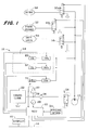
- a vehicle hydraulic system 10 such as for an agricultural tractor, includes a hydraulic supply pump 12 which supplies system pressure hydraulic fluid to various hydraulic functions or elements, such as mechanical front wheel drive (MFWD) control element 50, a park brake element 52, a differential lock control element 54, etc., via a corresponding solenoid operated control valve 16A, 16B, 16C, etc.
- the MFWD control element 50 is preferably a spring engaged, pressure released unit, and which is normally engaged during field operation of the tractor.
- the park brake element 52 is preferably a spring engaged, pressure released park brake, which is released when the tractor is moving.
- the differential lock control element 54 is preferably a pressure engaged, spring disengaged differential lock unit which is normally disengaged.
- the pump 12 also supplies system pressure to a plurality of other hydraulic elements, such as transmission control clutch elements 60, 62, of a conventional powershift transmission 64, such as the powershift transmission on 8000 Series John Deere tractors, and/or a PTO control clutch element 70.
- a conventional powershift transmission 64 such as the powershift transmission on 8000 Series John Deere tractors
- PTO control clutch element 70 a PTO control clutch element 70.
- Each of these further elements is coupled to the pump 12 via a corresponding conventional element control valves 20A, 20B, 20C, etc.
- the term hydraulic function or element should be understood to include other known hydraulically operated functions which are used on vehicles such as agricultural tractors or other agricultural work vehicles or machines. Although only two transmission control clutch elements 60, 62 are shown it should be understood that there would be as many such elements as are part of a typical powershift transmission.
- each element control valve 20A, 20B, 20C, etc. includes a solenoid operated valve section 21 and a pilot operated section 23.
- the pilot operated section 23 is normally spring biased to a position which blocks communication between pump 12 and the element, and valve section 21 normally connects the pilot side of valve section 23 to sump.
- valve section 21 normally connects the pilot side of valve section 23 to sump.
- the pump 12 also supplies lubrication fluid to a transmission lube circuit 22 via a pressure regulating and system priority valve 24, an oil cooler 26 and hydraulic lube line 28.
- the monitoring and control system of the present invention includes an oil temperature sensor 30 which senses the temperature of lube fluid in line 28, a pressure sensor 32 which senses the pressure P of lube fluid in line 28 and an engine speed sensor 34.
- a control unit 40 receives signals from sensors 30, 32 and 34, supplies control signals to valves 16 and 21, and supplies information to a display 42 via a conventional data bus 44.
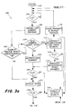
- the control unit 40 executes an algorithm 100 represented by the flow chart set forth in Figs. 3a - 3d. The conversion of this flow chart into a standard language for implementing the algorithm described by the flow chart in a digital computer or microprocessor, will be evident to one with ordinary skill in the art.
- step 104 determines whether the lube pressure P from sensor 32 is less than a threshold pressure Pt for a predetermined time period. If not, step 104 is repeated.
- the threshold pressure Pt varies as a function of engine speed and oil temperature, as sensed by sensors 34 and 30, respectively.
- the oil pump 12 is driven by the engine (not shown), therefore as engine speed goes up the pump provides more oil, therefore normal lube pressure is higher with higher engine speed.
- normal lube pressure is higher than 240 kpa at 2000 engine rpm but at 1000 engine rpm, normal lube pressure is higher than 60 kpa.
- normal oil pressure is greater than 240 kpa at 55 degrees C, at 25 degrees C, normal lube pressure is greater than 360 kpa.
- step 104 determines whether the lube pressure P from sensor 32 is less than threshold pressure Pt. If, in step 104 the lube pressure P from sensor 32 is less than threshold pressure Pt, then step 106 recalls from a memory the last element which was changed, and step 108 determines whether the element changed within a predetermined time period of lube pressure dropping below threshold pressure. If yes, step 110 determines whether the last element changed was a dual element transmission shift (meaning two elements in the transmission were changed at the same time to engage a gear). If not, step 108 directs the algorithm to step 122.
- step 110 determines whether the last element changed was a dual element transmission shift (meaning two elements in the transmission were changed at the same time to engage a gear). If not, step 108 directs the algorithm to step 122.
- step 110 If, in step 110, the last element changed was not a dual element transmission shift, step 118 depressurizes the single element that changed within the predetermined time period (closes communication between that element and the pump 12). If, in step 110, the last element changed was a dual element transmission shift, step 112 downshifts the transmission 64 and depressurizes one of the pair of elements involved in the dual element transmission shift, and step 114 again compares the lube pressure P from sensor 32 to the threshold pressure Pt.
- step 114 If, in step 114, the lube pressure P is less than threshold pressure Pt, control is directed to step 116 which downshifts the transmission 64, depressurizes the other element involved in the dual element transmission shift when lube pressure became less than threshold pressure and directs the algorithm to step 120. If, in step 114, the lube pressure P is not less than threshold pressure Pt, control is directed to step 124 which disables and locks out that transmission element from pump 12 until the tractor is serviced.
- Step 120 is performed after either step 118 or 116, and again determines whether the lube pressure P from sensor 32 is less than a threshold pressure Pt for a predetermined time period. If, in step 120, the lube pressure P is not less than threshold pressure Pt, control is directed to step 124. If, in step 120, the lube pressure P is less than threshold pressure Pt, control is directed to step 122 which engages the MFWD 50 by closing valve 16a and disconnecting MFWD 50 from pump 12.
- Step 123 is performed after step 122, and again determines whether the lube pressure P from sensor 32 is less than a threshold pressure Pt for a predetermined time period. If, in step 123, the lube pressure P is not less than threshold pressure Pt, control is directed to step 124 which disables and locks out the disengagement of the MFWD. Step 124 directs the algorithm to step 125 which stores, transmits and displays a corresponding warning message or signal. Step 125 transmits on bus 44 a message that certain element(s) have been disabled and causes display 42 to flash a corresponding indication that element(s) have been disabled, including element(s) effecting transmission gears, and stores this message in memory. Step 125 then directs the algorithm back to step 104.
- Step 123 If, in step 123, the lube pressure P is less than threshold pressure Pt, control is directed to step 126. Step 126 depressurizes the differential lock 54, if the differential lock 54 was engaged.
- Step 128 again determines whether the lube pressure P from sensor 32 is less than a threshold pressure Pt for a predetermined time period. If not, it is assumed that there is a leak in the circuit to differential lock 54, and steps 124 and 125 are executed. If yes, step 130 downshifts the transmission 64 by one gear ratio.
- step 132 If, in step 132, the lube pressure P is not less than threshold pressure Pt, control is directed to step 134. If, in step 132, the lube pressure P is less than threshold pressure Pt, control is directed to step 150.
- step 134 the transmission downshift is checked to see if the shift was a dual element transmission shift (meaning two elements in the transmission were changed at the same time to engage the new gear). If no, the downshift is a single element shift (meaning only one clutch element was changed to engage the new gear). As a result, the one clutch element that was disengaged (depressurized) in the shift is now identified as the element causing low lube pressure.
- Step 136 clears the transmission gears and elements shifted through and directs the algorithm to steps 124 and 125 to lock-out the element, store that the element is locked-out and generate and transmit a message.
- step 138 recalls the elements which have already been shifted through while downshifting and directs the algorithm to step 140.
- the controller may be able to diagnose which clutch element is causing a system leak even during a dual element shift. For example, if 6 th gear is engaged (6 th gear in the transmission 64 engages a C1 input clutch (not shown) and a C output clutch (not shown)) and the lube pressure is below threshold pressure, then step 130 downshifts the transmission to 5 th gear. Shifting from 6 th gear to 5 th gear is a single element clutch swap.
- Step 140 checks for this type of situation by looking to see if one element was shifted through twice.
- step 140 directs the algorithm to steps 136, 124 and 125. If no element was shifted through twice, step 140 directs the algorithm to step 142, which downshifts the transmission 64 to a gear that engages one of the clutch elements that was engaged before the dual element transmission shift that eliminated the low lube pressure condition.
- Step 144 again compares the lube pressure P from sensor 32 to the threshold pressure Pt. If, in step 144, the lube pressure P is not less than threshold pressure Pt, control is directed to step 146. If, in step 132, the lube pressure P is less than threshold pressure Pt, control is directed to step 152.
- Step 146 downshifts the transmission 64 to a gear that engages the other clutch element that was engaged before the dual element transmission shift that eliminated the low lube pressure condition, and directs the algorithm to step 148.
- Step 148 again compares the lube pressure P from sensor 32 to the threshold pressure Pt. If, in step 148, the lube pressure P is not less than threshold pressure Pt, control is directed to step 104. If, in step 148, the lube pressure P is less than threshold pressure Pt, control is directed to step 152.
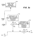
- step 150 if the transmission is not in neutral, control is directed to step 152, else control is directed to step 154.
- Step 152 stores in a memory of the VCU 40 the transmission elements which were shifted through when downshifting to neutral and directs control to step 130.
- step 154 if the PTO 70 is not engaged, control is directed to step 162, else control is directed to step 156.
- Step 156 depressurizes or disengages the PTO 70 by causing valve 20 to close communication between pump 12 and PTO 70.
- Step 158 compares the lube pressure P from sensor 32 to the threshold pressure Pt. If the lube pressure P is not less than threshold pressure Pt, control is directed to step 160 which locks out the PTO 70 and directs the algorithm to step 125. If the lube pressure P is less than threshold pressure Pt, control is directed to step 162.
- Step 162 engages the park brake by closing valve 16b.
- Step 164 again compares the lube pressure P from sensor 32 to the threshold pressure Pt. If the lube pressure P is not less than threshold pressure Pt, control is directed to step 166 which disables or locks-out neutral and the transmission gears. This is because the park brake release system is causing the leak. The algorithm then goes to step 125. If the lube pressure P is less than threshold pressure Pt, control is directed to step 168.
- Step 168 disables all elements and enables a limp home mode wherein only a pre-selected forward and reverse gear can be accessed by the operator. This allows the vehicle to be driven onto a truck or to the dealer for service.
- the forward and reverse gear is chosen so that the bearings in the transmission are moving at a relatively low speed so there is minimal risk of transmission damage under low lube conditions.
- Step 170 stores, transmits and displays a warning message, after which the algorithm 100 ends.
Landscapes
- Engineering & Computer Science (AREA)
- General Engineering & Computer Science (AREA)
- Mechanical Engineering (AREA)
- Physics & Mathematics (AREA)
- Fluid Mechanics (AREA)
- Control Of Transmission Device (AREA)
- Fluid-Pressure Circuits (AREA)
- Testing Of Devices, Machine Parts, Or Other Structures Thereof (AREA)
- General Details Of Gearings (AREA)
Applications Claiming Priority (3)
| Application Number | Priority Date | Filing Date | Title |
|---|---|---|---|
| US974356 | 2001-10-09 | ||
| US09/974,356 US6470247B1 (en) | 2001-10-09 | 2001-10-09 | Vehicle hydraulic system monitoring system and method |
| EP02772346A EP1436532B1 (de) | 2001-10-09 | 2002-09-26 | Fahrzeug-hydraulik-überwachungssystem und methode |
Related Parent Applications (2)
| Application Number | Title | Priority Date | Filing Date |
|---|---|---|---|
| EP02772346A Division EP1436532B1 (de) | 2001-10-09 | 2002-09-26 | Fahrzeug-hydraulik-überwachungssystem und methode |
| EP02772346.9 Division | 2002-09-26 |
Publications (3)
| Publication Number | Publication Date |
|---|---|
| EP1541901A2 true EP1541901A2 (de) | 2005-06-15 |
| EP1541901A3 EP1541901A3 (de) | 2005-11-16 |
| EP1541901B1 EP1541901B1 (de) | 2007-01-24 |
Family
ID=25521935
Family Applications (2)
| Application Number | Title | Priority Date | Filing Date |
|---|---|---|---|
| EP05100820A Expired - Lifetime EP1541901B1 (de) | 2001-10-09 | 2002-09-26 | Fahrzeug-Hydraulik-Überwachungssystem und Methode |
| EP02772346A Expired - Lifetime EP1436532B1 (de) | 2001-10-09 | 2002-09-26 | Fahrzeug-hydraulik-überwachungssystem und methode |
Family Applications After (1)
| Application Number | Title | Priority Date | Filing Date |
|---|---|---|---|
| EP02772346A Expired - Lifetime EP1436532B1 (de) | 2001-10-09 | 2002-09-26 | Fahrzeug-hydraulik-überwachungssystem und methode |
Country Status (9)
| Country | Link |
|---|---|
| US (1) | US6470247B1 (de) |
| EP (2) | EP1541901B1 (de) |
| AT (2) | ATE304136T1 (de) |
| AU (1) | AU2002300958B2 (de) |
| BR (1) | BR0204099A (de) |
| CA (1) | CA2404203A1 (de) |
| DE (2) | DE60217933T2 (de) |
| UA (1) | UA74295C2 (de) |
| WO (1) | WO2003031846A1 (de) |
Cited By (1)
| Publication number | Priority date | Publication date | Assignee | Title |
|---|---|---|---|---|
| US9752675B2 (en) | 2013-03-26 | 2017-09-05 | Deere & Company | Transmission control circuit |
Families Citing this family (15)
| Publication number | Priority date | Publication date | Assignee | Title |
|---|---|---|---|---|
| GB0625832D0 (en) * | 2006-12-22 | 2007-02-07 | Ricardo Uk Ltd | Real-time in cycle engine model |
| US8770014B2 (en) * | 2007-03-13 | 2014-07-08 | GM Global Technology Operations LLC | System for detecting hydraulic fluid leaks |
| US9291523B2 (en) * | 2007-08-07 | 2016-03-22 | Deere & Company | Automated diagnostics for crawler transmission hydraulic circuits |
| DE102010008680A1 (de) * | 2010-02-19 | 2011-08-25 | Dr. Ing. h.c. F. Porsche Aktiengesellschaft, 70435 | Verfahren zur Steuerung eines Antriebsstrangs in einem Kraftfahrzeug, Antriebsstrangsteuerung für ein Kraftfahrzeug, Steuereinheit für eine Fördereinrichtung zur Bereitstellung von Öldruck in einem Kraftfahrzeug, Verfahren zur Fehlererkennung in einem Hydrauliksystem für ein Kraftfahrzeug und Hydrauliksystem für ein Kraftfahrzeug |
| DE102011076846A1 (de) * | 2011-06-01 | 2012-12-06 | Zf Friedrichshafen Ag | Fahrzeuggetriebe |
| DE102011089017B4 (de) * | 2011-12-19 | 2022-11-17 | Zf Friedrichshafen Ag | Hydrauliksystem eines landwirtschaftlichen oder kommunalen Nutzfahrzeugs, sowie Verfahren zum Betreiben eines Hydrauliksystems |
| CN104704337B (zh) * | 2012-10-05 | 2018-01-12 | 伊顿公司 | 自动漏油检测系统 |
| WO2014127368A1 (en) | 2013-02-18 | 2014-08-21 | Harnischfeger Technologies, Inc. | Systems and methods for monitoring a fluid system of a mining machine |
| US9458903B2 (en) | 2013-03-14 | 2016-10-04 | Harnischfeger Technologies, Inc. | System and method for monitoring a brake system of a mining machine |
| CN107269625B (zh) * | 2017-06-27 | 2018-12-21 | 陕西法士特齿轮有限责任公司 | 一种液力自动变速器液压阀块测试系统及方法 |
| CN109882262B (zh) * | 2019-03-16 | 2024-11-01 | 连云港天明装备有限公司 | 矿用辅助运输车辆发动机机油保护装置 |
| US11117562B2 (en) * | 2019-09-18 | 2021-09-14 | Caterpillar Sarl | Hydraulic valve module and method for supplying hydraulic pressure to circuits of a vehicle |
| CN113917115B (zh) * | 2020-07-08 | 2023-09-01 | 广州汽车集团股份有限公司 | 变速器润滑油含气量检测系统、方法、装置及存储介质 |
| EP4232219A4 (de) * | 2020-10-23 | 2024-10-02 | Unist, Inc. | Schmiermittelzufuhrsystem und -verfahren |
| MX2021008659A (es) * | 2021-07-16 | 2023-01-17 | Gonzalez Jose Antonio Veliz | Metodo y aplicacion para eliminar la cavitacion gaseosa. |
Family Cites Families (9)
| Publication number | Priority date | Publication date | Assignee | Title |
|---|---|---|---|---|
| US4445168A (en) | 1981-06-24 | 1984-04-24 | Houdaille Industries, Inc. | Apparatus and method for micro-computer control of lubrication system |
| US4489311A (en) | 1982-05-17 | 1984-12-18 | Deere & Company | Engine oil pressure monitor |
| US4488140A (en) | 1982-05-17 | 1984-12-11 | Deere & Company | Clutch temperature monitor |
| US4489305A (en) | 1982-05-17 | 1984-12-18 | Deere & Company | Monitor for hydraulic transmission |
| US4640401A (en) | 1985-05-02 | 1987-02-03 | Deere & Company | Vehicle clutch lube control system |
| US4809544A (en) * | 1986-11-14 | 1989-03-07 | Jack Magoolaghan | Universal method and apparatus for testing a valve body for an automatic transmission |
| KR0143765B1 (ko) * | 1989-04-07 | 1998-08-01 | 라이문트 라우에 | 변속장치를 가지는 구동장치 |
| DE4340735A1 (de) * | 1992-11-30 | 1994-06-09 | Mazda Motor | Antriebssystem für ein selbstfahrendes Fahrzeug |
| DE69519177T2 (de) * | 1994-07-07 | 2001-05-23 | Hyundai Motor Co., Seoul/Soul | Verfahren zum Steuern des Hydraulikdrucks in automatischen Getrieben |
-
2001
- 2001-10-09 US US09/974,356 patent/US6470247B1/en not_active Expired - Lifetime
-
2002
- 2002-09-10 AU AU2002300958A patent/AU2002300958B2/en not_active Ceased
- 2002-09-19 CA CA002404203A patent/CA2404203A1/en not_active Abandoned
- 2002-09-26 EP EP05100820A patent/EP1541901B1/de not_active Expired - Lifetime
- 2002-09-26 AT AT02772346T patent/ATE304136T1/de not_active IP Right Cessation
- 2002-09-26 DE DE60217933T patent/DE60217933T2/de not_active Expired - Lifetime
- 2002-09-26 WO PCT/EP2002/010778 patent/WO2003031846A1/en not_active Ceased
- 2002-09-26 UA UA20040503449A patent/UA74295C2/uk unknown
- 2002-09-26 DE DE60206066T patent/DE60206066T2/de not_active Expired - Lifetime
- 2002-09-26 AT AT05100820T patent/ATE352735T1/de not_active IP Right Cessation
- 2002-09-26 EP EP02772346A patent/EP1436532B1/de not_active Expired - Lifetime
- 2002-10-08 BR BR0204099-9A patent/BR0204099A/pt active Search and Examination
Cited By (1)
| Publication number | Priority date | Publication date | Assignee | Title |
|---|---|---|---|---|
| US9752675B2 (en) | 2013-03-26 | 2017-09-05 | Deere & Company | Transmission control circuit |
Also Published As
| Publication number | Publication date |
|---|---|
| EP1541901B1 (de) | 2007-01-24 |
| WO2003031846A1 (en) | 2003-04-17 |
| EP1436532A1 (de) | 2004-07-14 |
| ATE352735T1 (de) | 2007-02-15 |
| US6470247B1 (en) | 2002-10-22 |
| BR0204099A (pt) | 2003-09-16 |
| ATE304136T1 (de) | 2005-09-15 |
| DE60206066T2 (de) | 2006-05-04 |
| DE60217933D1 (de) | 2007-03-15 |
| EP1541901A3 (de) | 2005-11-16 |
| DE60206066D1 (de) | 2005-10-13 |
| CA2404203A1 (en) | 2003-04-09 |
| AU2002300958B2 (en) | 2007-08-16 |
| DE60217933T2 (de) | 2007-05-31 |
| EP1436532B1 (de) | 2005-09-07 |
| UA74295C2 (uk) | 2005-11-15 |
Similar Documents
| Publication | Publication Date | Title |
|---|---|---|
| EP1541901B1 (de) | Fahrzeug-Hydraulik-Überwachungssystem und Methode | |
| US5893892A (en) | Vibration sensing and diagnostic system for vehicle drive train components | |
| JP2002147597A (ja) | 車両用自動変速機の制御装置 | |
| JP3194094B2 (ja) | 変速機用潤滑油の温度/粘度の測定方法およびその装置 | |
| US5088353A (en) | Failure detecting system for automatic power transmission | |
| US5830106A (en) | Malfunction judgment system of oil temperature sensor for automatic transmission | |
| US5493928A (en) | Transmission control default operation | |
| US7421326B2 (en) | Clutch fault detection | |
| US5596496A (en) | Vibration sensing and diagnostic system for transmission assembly | |
| EP1439333B1 (de) | Fahrzeuggetriebe und Verfahren zu dessen Steuerung | |
| JPH1151082A (ja) | クラッチ制御装置及びその制御方法 | |
| CN112867653B (zh) | 响应于发动机通信丢失来控制变速器档位的方法及其系统 | |
| US8092342B2 (en) | Method for adapting an automated transmission of a heavy vehicle in consideration of a speed sensitive PTO | |
| US4873880A (en) | Gearbox with electronically-controlled hydraulic clutches, for agricultural tractors and similar vehicles | |
| US5643137A (en) | Lockup control apparatus for automatic transmission and the method thereof | |
| JP4853634B2 (ja) | 作業車両 | |
| US10801612B1 (en) | Machine transmission with clutch element hydraulic control | |
| US11662018B1 (en) | Method and system for diagnosing a vehicle oil leak | |
| KR101091486B1 (ko) | 자동변속기의 유압 제어 시스템 | |
| US20220186829A1 (en) | Fault detection for a torque converter | |
| MANUAL | 9-Speed | |
| JPH11270662A (ja) | 多段変速機の切替装置 | |
| JPH08118988A (ja) | 制動エネルギ回生装置 |
Legal Events
| Date | Code | Title | Description |
|---|---|---|---|
| PUAI | Public reference made under article 153(3) epc to a published international application that has entered the european phase |
Free format text: ORIGINAL CODE: 0009012 |
|
| AC | Divisional application: reference to earlier application |
Ref document number: 1436532 Country of ref document: EP Kind code of ref document: P |
|
| AK | Designated contracting states |
Kind code of ref document: A2 Designated state(s): AT BE BG CH CY CZ DE DK EE ES FI FR GB GR IE IT LI LU MC NL PT SE SK TR |
|
| PUAL | Search report despatched |
Free format text: ORIGINAL CODE: 0009013 |
|
| AK | Designated contracting states |
Kind code of ref document: A3 Designated state(s): AT BE BG CH CY CZ DE DK EE ES FI FR GB GR IE IT LI LU MC NL PT SE SK TR |
|
| 17P | Request for examination filed |
Effective date: 20060516 |
|
| AKX | Designation fees paid |
Designated state(s): AT BE BG CH CY CZ DE DK EE ES FI FR GB GR IE IT LI LU MC NL PT SE SK TR |
|
| GRAP | Despatch of communication of intention to grant a patent |
Free format text: ORIGINAL CODE: EPIDOSNIGR1 |
|
| GRAS | Grant fee paid |
Free format text: ORIGINAL CODE: EPIDOSNIGR3 |
|
| GRAA | (expected) grant |
Free format text: ORIGINAL CODE: 0009210 |
|
| AC | Divisional application: reference to earlier application |
Ref document number: 1436532 Country of ref document: EP Kind code of ref document: P |
|
| AK | Designated contracting states |
Kind code of ref document: B1 Designated state(s): AT BE BG CH CY CZ DE DK EE ES FI FR GB GR IE IT LI LU MC NL PT SE SK TR |
|
| PG25 | Lapsed in a contracting state [announced via postgrant information from national office to epo] |
Ref country code: AT Free format text: LAPSE BECAUSE OF FAILURE TO SUBMIT A TRANSLATION OF THE DESCRIPTION OR TO PAY THE FEE WITHIN THE PRESCRIBED TIME-LIMIT Effective date: 20070124 Ref country code: LI Free format text: LAPSE BECAUSE OF FAILURE TO SUBMIT A TRANSLATION OF THE DESCRIPTION OR TO PAY THE FEE WITHIN THE PRESCRIBED TIME-LIMIT Effective date: 20070124 Ref country code: FI Free format text: LAPSE BECAUSE OF FAILURE TO SUBMIT A TRANSLATION OF THE DESCRIPTION OR TO PAY THE FEE WITHIN THE PRESCRIBED TIME-LIMIT Effective date: 20070124 Ref country code: NL Free format text: LAPSE BECAUSE OF FAILURE TO SUBMIT A TRANSLATION OF THE DESCRIPTION OR TO PAY THE FEE WITHIN THE PRESCRIBED TIME-LIMIT Effective date: 20070124 Ref country code: DK Free format text: LAPSE BECAUSE OF FAILURE TO SUBMIT A TRANSLATION OF THE DESCRIPTION OR TO PAY THE FEE WITHIN THE PRESCRIBED TIME-LIMIT Effective date: 20070124 Ref country code: CH Free format text: LAPSE BECAUSE OF FAILURE TO SUBMIT A TRANSLATION OF THE DESCRIPTION OR TO PAY THE FEE WITHIN THE PRESCRIBED TIME-LIMIT Effective date: 20070124 |
|
| REG | Reference to a national code |
Ref country code: GB Ref legal event code: FG4D |
|
| REG | Reference to a national code |
Ref country code: CH Ref legal event code: EP |
|
| REG | Reference to a national code |
Ref country code: IE Ref legal event code: FG4D |
|
| REF | Corresponds to: |
Ref document number: 60217933 Country of ref document: DE Date of ref document: 20070315 Kind code of ref document: P |
|
| PG25 | Lapsed in a contracting state [announced via postgrant information from national office to epo] |
Ref country code: SE Free format text: LAPSE BECAUSE OF FAILURE TO SUBMIT A TRANSLATION OF THE DESCRIPTION OR TO PAY THE FEE WITHIN THE PRESCRIBED TIME-LIMIT Effective date: 20070424 Ref country code: BG Free format text: LAPSE BECAUSE OF FAILURE TO SUBMIT A TRANSLATION OF THE DESCRIPTION OR TO PAY THE FEE WITHIN THE PRESCRIBED TIME-LIMIT Effective date: 20070424 |
|
| PG25 | Lapsed in a contracting state [announced via postgrant information from national office to epo] |
Ref country code: ES Free format text: LAPSE BECAUSE OF FAILURE TO SUBMIT A TRANSLATION OF THE DESCRIPTION OR TO PAY THE FEE WITHIN THE PRESCRIBED TIME-LIMIT Effective date: 20070505 |
|
| PG25 | Lapsed in a contracting state [announced via postgrant information from national office to epo] |
Ref country code: PT Free format text: LAPSE BECAUSE OF FAILURE TO SUBMIT A TRANSLATION OF THE DESCRIPTION OR TO PAY THE FEE WITHIN THE PRESCRIBED TIME-LIMIT Effective date: 20070625 |
|
| ET | Fr: translation filed | ||
| REG | Reference to a national code |
Ref country code: CH Ref legal event code: PL |
|
| NLV1 | Nl: lapsed or annulled due to failure to fulfill the requirements of art. 29p and 29m of the patents act | ||
| PG25 | Lapsed in a contracting state [announced via postgrant information from national office to epo] |
Ref country code: SK Free format text: LAPSE BECAUSE OF FAILURE TO SUBMIT A TRANSLATION OF THE DESCRIPTION OR TO PAY THE FEE WITHIN THE PRESCRIBED TIME-LIMIT Effective date: 20070124 |
|
| PLBE | No opposition filed within time limit |
Free format text: ORIGINAL CODE: 0009261 |
|
| STAA | Information on the status of an ep patent application or granted ep patent |
Free format text: STATUS: NO OPPOSITION FILED WITHIN TIME LIMIT |
|
| 26N | No opposition filed |
Effective date: 20071025 |
|
| PG25 | Lapsed in a contracting state [announced via postgrant information from national office to epo] |
Ref country code: BE Free format text: LAPSE BECAUSE OF FAILURE TO SUBMIT A TRANSLATION OF THE DESCRIPTION OR TO PAY THE FEE WITHIN THE PRESCRIBED TIME-LIMIT Effective date: 20070124 Ref country code: CZ Free format text: LAPSE BECAUSE OF FAILURE TO SUBMIT A TRANSLATION OF THE DESCRIPTION OR TO PAY THE FEE WITHIN THE PRESCRIBED TIME-LIMIT Effective date: 20070124 |
|
| PG25 | Lapsed in a contracting state [announced via postgrant information from national office to epo] |
Ref country code: GR Free format text: LAPSE BECAUSE OF FAILURE TO SUBMIT A TRANSLATION OF THE DESCRIPTION OR TO PAY THE FEE WITHIN THE PRESCRIBED TIME-LIMIT Effective date: 20070425 Ref country code: MC Free format text: LAPSE BECAUSE OF NON-PAYMENT OF DUE FEES Effective date: 20070930 |
|
| PG25 | Lapsed in a contracting state [announced via postgrant information from national office to epo] |
Ref country code: IE Free format text: LAPSE BECAUSE OF NON-PAYMENT OF DUE FEES Effective date: 20070926 |
|
| PG25 | Lapsed in a contracting state [announced via postgrant information from national office to epo] |
Ref country code: EE Free format text: LAPSE BECAUSE OF FAILURE TO SUBMIT A TRANSLATION OF THE DESCRIPTION OR TO PAY THE FEE WITHIN THE PRESCRIBED TIME-LIMIT Effective date: 20070124 |
|
| PG25 | Lapsed in a contracting state [announced via postgrant information from national office to epo] |
Ref country code: CY Free format text: LAPSE BECAUSE OF FAILURE TO SUBMIT A TRANSLATION OF THE DESCRIPTION OR TO PAY THE FEE WITHIN THE PRESCRIBED TIME-LIMIT Effective date: 20070124 |
|
| PG25 | Lapsed in a contracting state [announced via postgrant information from national office to epo] |
Ref country code: LU Free format text: LAPSE BECAUSE OF NON-PAYMENT OF DUE FEES Effective date: 20070926 |
|
| PG25 | Lapsed in a contracting state [announced via postgrant information from national office to epo] |
Ref country code: TR Free format text: LAPSE BECAUSE OF FAILURE TO SUBMIT A TRANSLATION OF THE DESCRIPTION OR TO PAY THE FEE WITHIN THE PRESCRIBED TIME-LIMIT Effective date: 20070124 |
|
| PGFP | Annual fee paid to national office [announced via postgrant information from national office to epo] |
Ref country code: GB Payment date: 20090929 Year of fee payment: 8 |
|
| PGFP | Annual fee paid to national office [announced via postgrant information from national office to epo] |
Ref country code: IT Payment date: 20090925 Year of fee payment: 8 |
|
| GBPC | Gb: european patent ceased through non-payment of renewal fee |
Effective date: 20100926 |
|
| PG25 | Lapsed in a contracting state [announced via postgrant information from national office to epo] |
Ref country code: IT Free format text: LAPSE BECAUSE OF NON-PAYMENT OF DUE FEES Effective date: 20100926 |
|
| REG | Reference to a national code |
Ref country code: FR Ref legal event code: ST Effective date: 20110531 |
|
| PG25 | Lapsed in a contracting state [announced via postgrant information from national office to epo] |
Ref country code: FR Free format text: LAPSE BECAUSE OF NON-PAYMENT OF DUE FEES Effective date: 20100930 |
|
| PG25 | Lapsed in a contracting state [announced via postgrant information from national office to epo] |
Ref country code: GB Free format text: LAPSE BECAUSE OF NON-PAYMENT OF DUE FEES Effective date: 20100926 |
|
| PGFP | Annual fee paid to national office [announced via postgrant information from national office to epo] |
Ref country code: FR Payment date: 20091006 Year of fee payment: 8 |
|
| PGFP | Annual fee paid to national office [announced via postgrant information from national office to epo] |
Ref country code: DE Payment date: 20160819 Year of fee payment: 15 |
|
| REG | Reference to a national code |
Ref country code: DE Ref legal event code: R119 Ref document number: 60217933 Country of ref document: DE |
|
| PG25 | Lapsed in a contracting state [announced via postgrant information from national office to epo] |
Ref country code: DE Free format text: LAPSE BECAUSE OF NON-PAYMENT OF DUE FEES Effective date: 20180404 |