EP1541948A2 - Strahlungsgerät eines Einbaukältegerätes - Google Patents
Strahlungsgerät eines Einbaukältegerätes Download PDFInfo
- Publication number
- EP1541948A2 EP1541948A2 EP04105500A EP04105500A EP1541948A2 EP 1541948 A2 EP1541948 A2 EP 1541948A2 EP 04105500 A EP04105500 A EP 04105500A EP 04105500 A EP04105500 A EP 04105500A EP 1541948 A2 EP1541948 A2 EP 1541948A2
- Authority
- EP
- European Patent Office
- Prior art keywords
- machine room
- blower fan
- condenser
- built
- lower side
- Prior art date
- Legal status (The legal status is an assumption and is not a legal conclusion. Google has not performed a legal analysis and makes no representation as to the accuracy of the status listed.)
- Granted
Links
Images







Classifications
-
- F—MECHANICAL ENGINEERING; LIGHTING; HEATING; WEAPONS; BLASTING
- F25—REFRIGERATION OR COOLING; COMBINED HEATING AND REFRIGERATION SYSTEMS; HEAT PUMP SYSTEMS; MANUFACTURE OR STORAGE OF ICE; LIQUEFACTION SOLIDIFICATION OF GASES
- F25D—REFRIGERATORS; COLD ROOMS; ICE-BOXES; COOLING OR FREEZING APPARATUS NOT OTHERWISE PROVIDED FOR
- F25D23/00—General constructional features
- F25D23/10—Arrangements for mounting in particular locations, e.g. for built-in type, for corner type
-
- F—MECHANICAL ENGINEERING; LIGHTING; HEATING; WEAPONS; BLASTING
- F25—REFRIGERATION OR COOLING; COMBINED HEATING AND REFRIGERATION SYSTEMS; HEAT PUMP SYSTEMS; MANUFACTURE OR STORAGE OF ICE; LIQUEFACTION SOLIDIFICATION OF GASES
- F25D—REFRIGERATORS; COLD ROOMS; ICE-BOXES; COOLING OR FREEZING APPARATUS NOT OTHERWISE PROVIDED FOR
- F25D19/00—Arrangement or mounting of refrigeration units with respect to devices or objects to be refrigerated, e.g. infrared detectors
-
- F—MECHANICAL ENGINEERING; LIGHTING; HEATING; WEAPONS; BLASTING
- F25—REFRIGERATION OR COOLING; COMBINED HEATING AND REFRIGERATION SYSTEMS; HEAT PUMP SYSTEMS; MANUFACTURE OR STORAGE OF ICE; LIQUEFACTION SOLIDIFICATION OF GASES
- F25D—REFRIGERATORS; COLD ROOMS; ICE-BOXES; COOLING OR FREEZING APPARATUS NOT OTHERWISE PROVIDED FOR
- F25D23/00—General constructional features
- F25D23/003—General constructional features for cooling refrigerating machinery
-
- F—MECHANICAL ENGINEERING; LIGHTING; HEATING; WEAPONS; BLASTING
- F25—REFRIGERATION OR COOLING; COMBINED HEATING AND REFRIGERATION SYSTEMS; HEAT PUMP SYSTEMS; MANUFACTURE OR STORAGE OF ICE; LIQUEFACTION SOLIDIFICATION OF GASES
- F25D—REFRIGERATORS; COLD ROOMS; ICE-BOXES; COOLING OR FREEZING APPARATUS NOT OTHERWISE PROVIDED FOR
- F25D23/00—General constructional features
- F25D23/08—Parts formed wholly or mainly of plastics materials
- F25D23/082—Strips
- F25D23/087—Sealing strips
-
- F—MECHANICAL ENGINEERING; LIGHTING; HEATING; WEAPONS; BLASTING
- F25—REFRIGERATION OR COOLING; COMBINED HEATING AND REFRIGERATION SYSTEMS; HEAT PUMP SYSTEMS; MANUFACTURE OR STORAGE OF ICE; LIQUEFACTION SOLIDIFICATION OF GASES
- F25D—REFRIGERATORS; COLD ROOMS; ICE-BOXES; COOLING OR FREEZING APPARATUS NOT OTHERWISE PROVIDED FOR
- F25D2323/00—General constructional features not provided for in other groups of this subclass
- F25D2323/002—Details for cooling refrigerating machinery
- F25D2323/0021—Details for cooling refrigerating machinery using air guides
-
- F—MECHANICAL ENGINEERING; LIGHTING; HEATING; WEAPONS; BLASTING
- F25—REFRIGERATION OR COOLING; COMBINED HEATING AND REFRIGERATION SYSTEMS; HEAT PUMP SYSTEMS; MANUFACTURE OR STORAGE OF ICE; LIQUEFACTION SOLIDIFICATION OF GASES
- F25D—REFRIGERATORS; COLD ROOMS; ICE-BOXES; COOLING OR FREEZING APPARATUS NOT OTHERWISE PROVIDED FOR
- F25D2323/00—General constructional features not provided for in other groups of this subclass
- F25D2323/002—Details for cooling refrigerating machinery
- F25D2323/0022—Details for cooling refrigerating machinery using multiple air flows
-
- F—MECHANICAL ENGINEERING; LIGHTING; HEATING; WEAPONS; BLASTING
- F25—REFRIGERATION OR COOLING; COMBINED HEATING AND REFRIGERATION SYSTEMS; HEAT PUMP SYSTEMS; MANUFACTURE OR STORAGE OF ICE; LIQUEFACTION SOLIDIFICATION OF GASES
- F25D—REFRIGERATORS; COLD ROOMS; ICE-BOXES; COOLING OR FREEZING APPARATUS NOT OTHERWISE PROVIDED FOR
- F25D2323/00—General constructional features not provided for in other groups of this subclass
- F25D2323/002—Details for cooling refrigerating machinery
- F25D2323/0026—Details for cooling refrigerating machinery characterised by the incoming air flow
- F25D2323/00261—Details for cooling refrigerating machinery characterised by the incoming air flow through the back bottom side
-
- F—MECHANICAL ENGINEERING; LIGHTING; HEATING; WEAPONS; BLASTING
- F25—REFRIGERATION OR COOLING; COMBINED HEATING AND REFRIGERATION SYSTEMS; HEAT PUMP SYSTEMS; MANUFACTURE OR STORAGE OF ICE; LIQUEFACTION SOLIDIFICATION OF GASES
- F25D—REFRIGERATORS; COLD ROOMS; ICE-BOXES; COOLING OR FREEZING APPARATUS NOT OTHERWISE PROVIDED FOR
- F25D2323/00—General constructional features not provided for in other groups of this subclass
- F25D2323/002—Details for cooling refrigerating machinery
- F25D2323/0026—Details for cooling refrigerating machinery characterised by the incoming air flow
- F25D2323/00264—Details for cooling refrigerating machinery characterised by the incoming air flow through the front bottom part
-
- F—MECHANICAL ENGINEERING; LIGHTING; HEATING; WEAPONS; BLASTING
- F25—REFRIGERATION OR COOLING; COMBINED HEATING AND REFRIGERATION SYSTEMS; HEAT PUMP SYSTEMS; MANUFACTURE OR STORAGE OF ICE; LIQUEFACTION SOLIDIFICATION OF GASES
- F25D—REFRIGERATORS; COLD ROOMS; ICE-BOXES; COOLING OR FREEZING APPARATUS NOT OTHERWISE PROVIDED FOR
- F25D2323/00—General constructional features not provided for in other groups of this subclass
- F25D2323/002—Details for cooling refrigerating machinery
- F25D2323/0026—Details for cooling refrigerating machinery characterised by the incoming air flow
- F25D2323/00266—Details for cooling refrigerating machinery characterised by the incoming air flow through the bottom
-
- F—MECHANICAL ENGINEERING; LIGHTING; HEATING; WEAPONS; BLASTING
- F25—REFRIGERATION OR COOLING; COMBINED HEATING AND REFRIGERATION SYSTEMS; HEAT PUMP SYSTEMS; MANUFACTURE OR STORAGE OF ICE; LIQUEFACTION SOLIDIFICATION OF GASES
- F25D—REFRIGERATORS; COLD ROOMS; ICE-BOXES; COOLING OR FREEZING APPARATUS NOT OTHERWISE PROVIDED FOR
- F25D2323/00—General constructional features not provided for in other groups of this subclass
- F25D2323/002—Details for cooling refrigerating machinery
- F25D2323/0027—Details for cooling refrigerating machinery characterised by the out-flowing air
- F25D2323/00271—Details for cooling refrigerating machinery characterised by the out-flowing air from the back bottom
-
- F—MECHANICAL ENGINEERING; LIGHTING; HEATING; WEAPONS; BLASTING
- F25—REFRIGERATION OR COOLING; COMBINED HEATING AND REFRIGERATION SYSTEMS; HEAT PUMP SYSTEMS; MANUFACTURE OR STORAGE OF ICE; LIQUEFACTION SOLIDIFICATION OF GASES
- F25D—REFRIGERATORS; COLD ROOMS; ICE-BOXES; COOLING OR FREEZING APPARATUS NOT OTHERWISE PROVIDED FOR
- F25D2323/00—General constructional features not provided for in other groups of this subclass
- F25D2323/002—Details for cooling refrigerating machinery
- F25D2323/0027—Details for cooling refrigerating machinery characterised by the out-flowing air
- F25D2323/00272—Details for cooling refrigerating machinery characterised by the out-flowing air from the back top
Definitions
- the present invention relates to a refrigerator , and more particularly, to a radiating apparatus of a built -in refrigerator that can improve heat radiation in a machine room of the refrigerator installed in a built -in cabinet.
- a refrigerator is an apparatus to maintain an inner space at a low temperature by repeating a cooling cycle consisting of compression, condensation, expansion and evaporation of a refrigerant, thereby freshly keeping foods cold or frozen for a long time.
- the refrigerator Since the refrigerator inevitably has a certain amount of volume, it is protruded out of a wall when installed on a wall of a kitchen or a living room. This is not good for a space saving as well as a beautiful appearance.
- a built-in refrigerator that is installed in a cabinet as a furniture, looking to be an integral part of the kitchen or the living room.
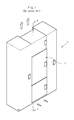
- Fig. 1 is a perspective view illustrating that a refrigerator body 2 is installed in a built -in cabinet 2 like a built-in furniture.
- the refrigerator body 2 installed in the built-in cabinet 1 is partitioned into a foods storage room and a machine room having a refrigerant circulation unit for maintaining an inside of the foods storage room at a low temperature.
- the refrigerator body 2 Owing to a characteristic of the built -in refrigerator, the refrigerator body 2 has an air flow passage in which air is introduced into the machine room through a lower side of the refrigerator and is discharged along a rear wall of the refrigerator.
- Fig. 2 is a sectional view taken along the line A -A' of Fig. 1.
- the built -in refrigerator includes the refrigerator body 2 installed in the built -in cabinet 1, a door panel 3 for opening/clos ing a cold storage room and a freezer, a base plate 4 for supporting the refrigerator body 2, a wall cover base 5 vertically installed at a lower side of a front side of the refrigerator body 2 and having a vent hole 9, a machine room 6 installed at a rear side of the refrigerator body 2, a suction passage 12 communicating with an exterior through a lower side of the base plate 4 and the vent hole 9 of the wall cover base 5, and an exhaust passage 13 disposed at a rear side of the refrigerator body 2.
- the refrigerator body 2 is inserted into a space provided as a built - in furniture in the built-in cabinet 1 spaced apart by a predetermined interval from a wall surface.
- the refrigerator body 2 has the door panel 3 at a front side thereof, a drawer cabinet at an upper portion thereof, and the base plate 4 at a lower portion thereof.
- the base plate 4 is installed at the lower side of the refrigerator body 2 spaced apart by a predetermined interval from a bottom surface of the refrigerator body 2 to support the refrigerator body 2.
- the wall cover base 5 is installed at the lower side of the front side of the refrigerator body 2 so as to maker better the appearance of the built -in cabinet 1 and block an introduction of garbage from an exterior.
- the machine room 6 is disposed at the rear and lower side of the refrigerator body 2.
- the machine room 6 includes a compressor 10, a condenser and a blower fan therein, and is protected by a back cover 7. Heat radiation in the machine room 6 is performed by air flowing through the back cover 7.
- heat generated in the machine room 6 is effectively irradiated through the heat radiation passages provided at the lower side and the rear side of the built -in cabinet 1.
- outer air is suctioned into the machine room 6 through the suction passage 12 formed at the lower side of the refrigerator body 2, and inner air of the machine room 6 is discharged through the exhaust passage 13 formed at the rear side of the refrigerator body 2.
- the outer air is introduced through the vent hole 9 of the wall cover base 5 installed at the front and lower side of the built-in cabinet, and the introduced air flows along the suction passage 12 installed between the base plate 4 installed at the lower side of the built-in cabinet 1, and the bottom surface, and along the exhaust passage 13 between the refrigerator body 2 and the wall surface 8.
- the air flowing along the passages 12 and 13 irradiates heat from the machine room 6 through the back cover 7.
- a refrigerant sequentially passing through the compressor, the condenser (see 17 of Fig. 3), and a capillary tube is introduced into an evaporator (not shown), and is completely vapori zed while passing through the evaporator, thereby depriving a surrounding of heat and cooling the surrounding. Thereafter, the air cooled by the evaporator is supplied to the cold storage room and the freezer, cooling the inside of the refrigerator, and t he temperature-elevated cool air is fed back and is introduced into the evaporator.
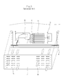
- Fig. 3 is a front view of the machine room of a related art built-in refrigerator.
- the machine room 6 is provided with the compressor 10 disposed at one side, the blower fan 16 disposed at the other side, and the condenser 17 disposed at a center of the machine room 6.
- the blower fan 16 operates, outer air is suctioned through suction holes 14 of the back cover 7, and the air blown by the blower fan 16 sequentially exchanges heat with the condenser 17 and the compressor 10 and is discharged through exhaust holes 15 of the back cover 7.
- the related air built -in refrigerator has the structure that heat radiation of the blower fan 16 and the condenser 17 of the machine room 6 is performed by inhaling air through the back cover 7 to exchange heat and again discharging the heat-exchanged air through the back cover 7, there may occur a circulation phenomenon that the air discharged from the machine room 6 is again suctioned into the suction holes 14 or is again introduced via the compressor 10, resultingin the lowering in the heat transfer efficiency.
- the present invention is directed to a radiating apparatus of a built-in refrigerator that substantially obviates one or more problems due to limitations and disadvantages of the related art.
- a first object of the present invention is to provide a radiating apparatus of a built -in refrigerator that can prevent a passage of an air suctioned into a machine room of the built -in refrigerator from being mixed with a passage of an air dis charged from the machine room.
- a second object of the present invention is to provide a radiating apparatus of a built -in refrigerator provided with an airflow guide member partitioning an inside/outside of a machine room into an upper side and a lower si de such that an air discharged from the machine room is not again introduced into the machine room.
- a third object of the present invention is to provide a radiating apparatus of a built -in refrigerator provided with an airflow guide member partitioning an inside/outside of a condensing part of a machine room into an upper side and a lower side, thereby guiding suction of an outer air and a discharge of a heat-exchanged air.
- a fourth object of the present invention is to provide a radiating apparatus of a built-in refrigerator provided with an airflow guide member partitioning an inside/outside of a machine room into an upper side and a lower side, thereby preventing an air suctioned into a machine room of the built -in refrigerator from being mixed with an air discharged from the machine room.
- a fifth object of the present invention is to provide a radiating apparatus of a built -in refrigerator having suction duct installed at a lower side of a machine room.
- a sixth object of the present invention is to provi de a radiating apparatus of a built -in refrigerator having a discharge passage guide for guiding a discharge air toward a read side of the built-in refrigerator up to a predetermined height.
- a radiating apparatus including: a refrigerator body installed in a built -in cabinet; a machine room disposed at a rear lower side of the refrigerator body; a compressor installed at one sid e of the machine room; a condenser and a blower fan installed at the other side of the machine room; and an airflow guide member installed between the blower fan and the condenser, for guiding suction of an external air toward the other side of the machine room and guiding a discharge of heat-exchanged air in the other side of the machine room.
- a radiating apparatus of a built -in refrigerator including: a refrigerator body installed in a built -in cabinet; a machine room disposed at a rear lower side of the refrigerator body; a compressor installed at one side of the machine room; a condenser and a blower fan installed on a radiating passage of the other side of the machine room; a back cover coup led to a rear side of the machine room so as to cover the machine room; and a discharge airflow guide part of which inside is opened such that an air discharged by the blower fan is induced to a predetermined height.
- a radiating apparatus of a built -in refrigerator comprising: a machine room including a compressor section in which a compressor is accommodated and a condenser section in which a condenser in which a refrigerant that passes through the compressor exchanges heat with air is accommodated; a blower fan for introducing the air into the machine room; a vertical barrier for partitioning the machine room into the compressor section and the condenser section; and an airflow guide horizontall y formed between the condenser and the blower fan, the airflow guide having one edge curved upward.
- a radiating apparatus of a built -in refrigerator including: a refrigerator body installed in a built-in cabinet; a machine room disposed at a rear lower side of the refrigerator body; a compressor installed at one side of the machine room; a condenser and a blower fan installed at a front and a rear side of the other side of the machine room; and a suction duct installed at the other lower side of the machine room, for guiding suction of an external air.
- a guide member for guiding an external air suctioned from a lower side of a built-in cabinet and an air that exchanges heat in the machine room and is discharged, not to be mixed with each other, is provided so as to more effectively radiate heat generated in the machine room.
- Fig. 1 is a perspective view illustrating a general built-in refrigerator according to the related art
- Fig. 2 is a sectional view taken along the line A -A' of Fig. 1;
- Fig. 3 is a schematic view illustrating a structure of a machine room according to the r elated art
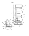
- Fig. 4 is a side sectional view of a radiating apparatus of a built-in refrigerator according to a first embodiment of the present invention
- Fig. 5 is an exploded perspective view of a radiating apparatus of a built-in refrigerator according to the first embodiment of the present invention
- Fig. 6 is a partial perspective view of a radiating apparatus of a built-in refrigerator according to the first embodiment of the present invention
- Fig. 7 is a rear view of a machine room of a built -in refrigerator according to an embodiment of the present invention.
- Figs. 8 and 9 are side sectional views of a built -in refrigerator having an improved condenser structure according to the present invention.
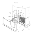
- Fig. 10 is an exploded perspective view of a built -in refrigerator according to a second embodiment of the present invention.
- Fig. 11 is a side sectional view of a radiating apparatus of a built-in refrigerator according to a third embodiment of the present invention.
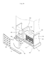
- Fig. 12 is an exploded perspective view of a radiating apparatus of a built-in refrigerator according to the third embodiment of the present invention.
- Fig. 13 is a rear view of a coupled radiating apparatus of a built-in refrigerator according to the third embodiment of the present invention.
- Fig. 14 is a perspective view illustrating an air passage structure according to the third embodiment of the present invention.
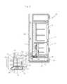
- Fig. 15 is a side sectional view of a radiating apparatus of a built-in refrigerator according to a fourth embodiment of the present invention.
- Fig. 16 is a partial exploded sectional view of a radiating apparatus of a built-in refrigerator according to the fourth embodiment of the present invention.
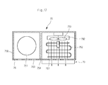
- Fig. 17 is a plane view of a radiating apparatus of a built-in refrigerator according to the fourth embodiment of the present invention.
- Figs. 4 through 7 are views illustrating a first embodiment of the present invention.
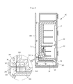
- Fig. 4 is a side sectional view of a radiating apparatus of a built -in refrigerator according to a first embodiment of the present invention
- Fig. 5 is an exploded perspective view of a radiating apparatus of a built-in refrigerator according to the first embodiment of the present invention
- Fig. 6 is a partial perspective view of a radiating apparatus of a built -in refrigerator according to the first embodiment of the present invention
- Fig. 7 is a rear view of a machine room of a built-in refrigerator according to an embodiment of the present invention.
- the built-in refrigerator includes a refrigerator bod y 31 installed in a built-in cabinet 30, a door panel 32 installed at afront side of the refrigerator, a base plate 33 and a wall cover base 34 disposed at a lower side of the refrigerator body 31, a machine room 35 installed at a rear lower side of the refrigerator body 31 and having a vertical plate 354 partitioning an inside thereof into a compressing section 358 and a condensing section 359 , an airflow guide part 390 for guiding suction and discharge of an external air by selectively shielding an upper side or a lower side of the condensing section 359, a back cover covering the condensing section 359 of the machine room 35, a suction passage 381 formed at a lower side of the refrigerator body 31, for inducing suction of the external air, and a radiation passage including a discharge passage 382 formed along an inner wall.
- the machine room 35 is designed such that a compressor 351 is disposed at the compressing section 358, a blower fan 353 and a condenser 352 are positioned at an upper side and a lower side of the condensing section 359, and the airflow guide part 390 is installed to shield an inside and an outside of the condensing section 359 in an upper and a lower direction.
- the airflow guide part 390 includes a first airflow guide 391 protruded toward a wall direction, for partitioning a space between a lower suction inlet 361 and an upper discharge outlet of the back cover 36, and a second airflow guide 392 provided therein with a suction hole 356, for partitioning a space between the condenser 352 disposed at the lower side of the machine room and the blower fan 353 disposed at the upper side of the machine room.
- the built-in cabinet 30 is installed therein with the refrigerator body 31, and the door panel 32 is installed at the front side of the refrigerator body 31.
- the base plate 33 and the wall cover base 34 are installed at a lower side of the built-in cabinet 30.
- the refrigerator body 31 is installed spaced away from the inner wall 27, and the machine room 35 for a cooling cycle is disposed at the rear lower side of the refrigerator body 31.
- the suction passage 381 and the dis charge passage 382 are respectively formed at the lower side and the rear side of the machine room 35.
- the machine room 35 is partitioned into the compressing section 358 and the condensing by the vertical plate 354 so that the compressing section 358 and the condensing section 359 are shielded by the vertical plate 354.
- the condensing section 359 is partitioned into an upper side and a lower side by the airflow guide part 390.
- the condenser352 is disposed at the partitioned lower side of the condensing section 359 and the blower fan 352 is disposed at the partitioned upper side.
- the airflow guide part 390 partitions the inside and the outside of the condensing part 359 into an upper side and a lower side.
- the airflow guide part 390 has the suction hole 356 communicating the condenser 352 with the blower fan 353 at the inside thereof, thereby forming an air passage between the condenser 352 and the blower fan 353.
- the compressing section 358 has the compressor 351 installed therein and is opened without any back cover.
- the condensing section 359 has the back cover 36 coupled thereto.
- the suction holes 361 and the discharge holes 362 are formed at the upper side and the lower side of the back cover 36 by the airflow guide part 390.
- the suction holes 361 and the discharge holes 362 are formed in plurality such that the suction holes 361 communicate with the condenser 352 and the discharge holes 362 communicate with the blower fan 353.
- the discharge holes 362 are formed in plurality within a rotational radius of the blower fan 353.
- a guide passing slot 363 is formed in a lateral direction such that the airflow guide part 390 passes through.
- the back cover 36 may be installed to cover both the condensing part and the compressing part, having a plurality of vent holes at left and right sides thereof.
- the back cover 36 is fixedly coupled to the vertical plate 354 and a side plate 357 by a screw, thereby protecting the condensing section 359.
- the airflow guide part 390 is a flat plate and is installed in a lateral direction at a central portion of the condensing section 358 between the vertical plate 354 and the side plate 357 of the machine room 357.
- the airflow guide part 390 is preferably designed such that both ends thereof are slidingly coupled into the vertical plate 354 and an inside of the machine room.
- the airflow guide part 390 is coupled by a coupling means such as a screw, or is formed integrally with the machine room inside the machine room.
- the first airflow guide 391 protruded to the inner wall in an outer direction of the machine room is formed integrally with the second airflow guide 392 extending by a width of the condenser 352 toward the inside direction of the refrigerator body.
- the back cover 36 As shown in Figs. 6 and 7, by disposing the back cover 36 at the condensing part 392 of the machine room 35 and passing the airflow guide part 390 through the guide passing slot 363 of the back cover 36, the first airflow guide 391 is disposed between the back cover and the inner wall 37, and the second airflow guide 392 is disposed between the condenser 352 and the blower fan 353. In this state, the back cover 36 is fixed to the machine room 35 by a screw.
- the compressor 351 and the condenser 352 of the machine room 35 generate heat and accordingly the blower fan 353 starts to operate.
- the external air is moved along the airflow guide part 390 and is then suctioned into the condensing section 359 of the machine room 35 through the suction holes 361 of the back cover 36.
- the air suctioned into the condensing section 359 exchanges heat with the condenser 352 to cool the condenser 352, and the heat-exchanged air is discharged through the discharge holes 362 of the back cover 36 by the operation of the blower fan 353.
- the air discharged by the condensing section 359 is not again introduced in a downward direction by the airflow guide part 390 but is exhausted to an outside through the discharge passage 382.
- the airflow guide part 390 defines the suction passage 381 and the discharge passage 382 at the lower side and the rear side of the refrigerator body 31 to form the airflow passage communicating with the condensing section 359 of the machine room 35, thereby preventing the heat -exchanged air from being again introduced into the machine room 35 together with external cool air to increase radiating effect.
- the airflow guide part 390 may be made in the form of a radiating plate.
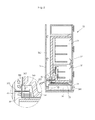
- Fig. 8 shows an example in which a condenser 38 having a different construction is employed in the first embodiment of the present invention.
- the vertical plate is installed in the machine room 35 to isolate the compressing section and the condensing section from each other.
- the condensing section 359 is partitioned into the upper side and the lower side by the airflow guide part 390.
- the blowerfan 353 is installed at the partitioned upper side and the condenser 38 is installed at the lower side of the condensing section 359.
- the condenser 38 has a tube, which extends from a lower end of the condensing section 359 to an inner suction opening 356 in the form of ' '.
- the tube of the condenser 38 extends from the lower end space of the condensing section 359 to a space where the inner suction opening is formed to increase the volume ratio, thereby increasing heat exchange area compared with the conventional refrigerator.
- Fig. 9 shows another example in which a condenser having a different construction is employed in the first embodiment of the present invention.
- the condenser 38 has a tube, which extends from a bottom surface of the condensing section 359 to an inner suction opening 356 in the form of ' ' having a curvature so as to increase the volume ratio.
- a vertical plate is installed in the machine room 35 to isolate the compressing section and the condensing section from each other.
- the condensing section 359 is partitioned into the upper side and the lower side by the airflow guide part 390.
- the blower fan 353 is installed at the partitioned upper side and the condenser 38 is installed at the lower side of the condensing section 359.
- Fig. 10 is an exploded perspective view of a built-in refrigerator according to a second embodiment of the present invention.
- a machine room 45 ispartitioned into a compressing section 458 and a condensing section 459.
- An airflow guide part 490 bent in the form of ' ⁇ ' is installed between the compressing section 458 and the condensing section 459.
- the airflow guide part 490 has a horizontal plate 491 and a vertical plate 492 integrally bent from one end of the horizontal plate 491.
- the horizontal plate 491 partition s the condensing section 459 into an upper side and a lower side and the vertical plate 492 partitions the machine room 45 into a left side and a right side.
- a blower fan 453 is disposed at the partitioned upper side of the condensing section 459 and a condenser 452 is disposed at the partitioned lower side of the condensing section 459.
- the machine room 45 is partitioned into the upper, lower, left and right sides by the ' ⁇ '-shaped airflow guide part 490.
- a suction opening 456 is formedin the machine room 45 so as to communicate the condenser 452 disposed at the lower side with the blower fan 453 disposed at the upper side.
- the ' ⁇ '-shaped airflow guide part 490 also extends to an outside of the machine room 45 to partition an outer space of the machine room 45 into upper/lower side and left/right side, thereby guiding an introduction of external air and at the same time preventing heat-exchanged air from being again introduced.
- a buffer member is installed at an end of the airflow guide part 490 so as to buffer an impact between an exterior (i.e., wall surface) and the airflow guide part 490.
- a back cover 46 has vent holes 464 communic ating with the compressor 351 at one side thereof, and discharge holes 462 and suction holes 461 at upper and lower sides of the other side thereof.
- a guide passing slot 463 having a ' ⁇ ' shape is formed along a central portion of the back cover 46 such th at the airflow guide part 490 is coupled.
- the airflow guide part 490 is inserted into the ' ⁇ '-shaped-guide passing slot 463 and is then fixed to a bottom or a side of the machine room 45 by a coupling means such as a screw. Alternatively, the airflow guide part 490 is fixed to the back cover 46 by a separate fixing member. Also, the airflow guide part 490 may be designed in a slidingly coupled or decoupled structure such that the refrigerator body can be freely moved.
- the airflow guide part 490 formed in the shape of ' ⁇ ' inside or outside the back cover 46 guides flow of air introduced into the machine room 45, and prevents air discharged from the machine room 45 from being again introduced into the lower side of the machine room 45.
- the machine room 45 further includes a side surface 457 having a plurality of radiation holes 493 such that external air enters into or goes out of the machine room 45 through the radiation holes 493.
- These radiation holes 493 allow an amount of air inside the machine room to be sufficientl y increased.
- the compressor 451 and the condenser 452 of the machine room 45 essentially generate heat and accordingly the blower fan 453 starts to operate.
- the air discharged by the blower fan 453 is discharged through the discharge holes 462 of the back cover 46 and is then exhausted to an outside through the discharge passage.
- the airflow guide part 490 is formed in the shape of ' ⁇ ' to shield the suction passage of external air from the discharge passage, thereby preventing the air discharged by the blower fan 453 from being mixed with the suctioned external air.
- Figs. 11 through 13 show a construction of a built -in refrigerator according to a third embodiment of the present invention.
- a machine room 55 is partitioned into a compressing section 558 and a condensing section 559 by a vertical plate 554 formed at a central portion thereof.
- a compressor 551 is disposed at the compressing section 558, and a blower fan 553 and a condenser 552 are positioned at an upper side and a lower side of the condensing section 559.
- a plurality of suction holes 557 are formed at a bottom plate of the machine room 55 throughout an entire area of the bottom plate such that external air is introduced through the suction holes 557.
- a vent opening 555 is formed at the vertical plate 554 to communicate the compressing section 558 with the condensing section 559.
- the machine room 55 is provided with a back cover 56 covering an entire rear side of the machine room 55.
- the back cover 56 has an airflow shielding plate 561 protruded from a rear lower side of the machine room 55 to an inner wall 57, and a discharge outlet 564 communicating with the blower fan 453 disposed at a right upper side of the machine room 55.
- An airflow guide 562 is installed at the discharge outlet 562 so as to guide a flow of discharged air.
- the airflow guide 562 is a duct structure extending by a predetermined height upward from the discharge outlet 564, and is installed at a rear surface of a refrigerator body 51 to communicate the discharge outlet 564 with a discharge passage 582.
- the blower fan 553 is installed with a slope upward such that the air discharged through the discharge outlet 564 is easily discharged through the airflow guide 562.
- the airflow guide 562 is designed to communicate with the discharge outlet 564 of the back cover 56, an inner airflow passage 563 and the discharge passage 582 and induces the air discharged through the discharge outlet 564 in an upward direction by a predetermined height.
- the discharge outlet of the back cover may be omitted by providing a structure that the air is directly discharged to the airflow guide 562.
- the compressor 551 and the condenser 552 of the machine room 55 essentially generate heat and accordingly the blower fan 553 starts to operate.
- the blower fan 553 operates, external air is suctioned through suction passage 581 and is then moved to a space where the compressor 551 and the condenser 552 are installed, through the suction holes 557 formed at the bottom plate of the machine room.
- the external air is introduced through a vent hole 541 of a wall cover base 54 and the suction passage 581 installed at a lower side of the built-in cabinet 50.
- the introduced air is induced into the machine room 55 along a passage between the base plate 54 and the bottom surface.
- the external air is suctioned through the sucti on holes 557 formed at the bottom plate of the machine room 55 through a space between the base plate 53 of the built -in cabinet 50 and the refrigerator body 51.
- the airflow shielding plate 561 shields the air suctioned through the suction passage 581 from being introduced into the discharge passage 582 and guides the air to be suctioned into the suction holes 557 as shown in Figs. 12 and 13.
- the air suctioned through the suction holes 557 formed at the bottom plate of the machine room 55 co ols the condenser 552 and is then discharged by the blower fan 553. At this time, the discharged air is discharged to a predetermined height along the airflow guide 562 of the back cover 56 and is then exhausted to an outside through the discharge passage 582.
- the airflow guide 562 has a closed circumference and an opened internal passage 563 such that the air is induced upward through the opened internal passage 563.
- the air suctioned through the bottom plate of the compressing section 558 is introduced into the condensing section 559 through the vent holes 555 formed at the vertical plate 554 of the machine room 55 and is again discharged to the airflow guide 562 by the blower fan 553, so that the compressor 551 is also radiated.
- Fig. 14 is a perspective view illustrating an air passage structure according to the third embodiment of the present invention.
- a machine room 65 is partitioned into a compressing section 658 and a condensing section 659 by a vertical plate 654.
- the compressing section 658 is isolated from the condensing section 659.
- the condensing section 659 is partitioned into an upper side and a lower side by a horizontal plate 655.
- a blower fan 653 and a condenser 652 are installed at the upper side and the lower side of the condensing section 659.
- a plurality of suction holes 657 are formed at a bottom plate of the machine room 65 such that external air is introduced through the suction holes 657.
- the machine room 65 is also provided with a back cove r 66.
- the back cover 66 has a plurality of vent holes 669 communicating with the compressor 651 at one side thereof, and an airflow shielding plate 661 outwardly protruded from a bottom end of the other side of the back cover 66.
- a radiation passage is provide d in which the airflow passage formed at the rear side of the machine room is shielded by the airflow shielding plate, external air is suctioned through the bottom plate of the machine room, and suctioned air is exhausted to an outside through the airflow guide part installed in a duct type having a predetermined height, thereby preventing heat exchange amount from being reduced due to the discharged air.
- Figs. 15 through 17 illustrate a fourth embodiment of the present invention.
- a machine room 75 has a suction duct 79 integrally formed with the machine room 75 at a lower side of the machine room 75.
- the suction duct 79 guides an external air to be introduced into a lower side of the machine room 75.
- the machine room 75 is partitioned into a compressing section 758 of a left side and a condensing section 759 of a right side by a vertical plate 754.
- a compressor 751 is disposed at the compressing section 758, and a condenser 752 and a blower fan 753 are respectively positioned at a front side and a rear side of the condensing section 759.
- the suction duct 79 is installed between a bottom surface of the machine room 75 and an upper surface of a base plate 73.
- the suctio n duct 79 is formed in the shape of ' ⁇ ', and has a suction inlet 791 communicating with a suction passage 781 and protruded downwardly at one side thereof such that an air introduced through a vent hole 741 of a wall cover base 74 is easily introduced into the machine room 75, and a discharge outlet 792 formed at the other side of the duct 79 and communicating with the condensing section 759 of the machine room 75 to induce the air introduced into the duct 79 to the condensing section 759 of the machine room 75.
- the external air exchanges heat with the condenser 793 to cool the co ndenser 793 and the heat-exchanged air is exhausted through a discharge hole 761 of the back cover 76.
- the air discharged through the discharge hole 761 of the back cover 76 is not again introduced through the suction inlet 791 of the suction duct 79 but is exhausted to an outside through a discharge passage 782. Since the back cover 76 has a plurality of vent holes 763 formed facing the compressor, heat is radiated by a natural circulation.
- the embodiments of the present invention illustra te various radiating apparatuses employed in a machine room. These radiating apparatuses shield the air suctioned into the machine room and the air discharged to the machine room, and are provided with a vertical plate or a horizontal plate for the shield ing, a duct or an airflow guide for easy introduction of a suctioned air and easy discharge of discharge air, thereby increasing heat exchange efficiency of the machine room.
- a radiating apparatus of a machine room of a built-in refrigerator As described above, a radiating apparatus of a machine room of a built-in refrigerator according to the present invention, the machine room is partitioned into an upper side and a lower side, and an air suction passage and an air discharge passage having an air exchanging heat with a condenser are shielded, thereby increasing heat exch ange efficiency compared with the related art radiating apparatus.
- the present invention guides passages of airs flowing according to suction and heat exchange of external air, and discharge of the external air not to be mixed with one another, thereby increasing heat exchange efficiency in the machine room.
- a condenser and a blower fan are respectively disposed at a lower side and an upper side of a machine room, and an airflow guide member for partitioning the machine room into an inside and an outside is installed to shield discharged air from being again introduced, thereby maximizing heat radiation in an inside of the machine room as well as in the condenser.
Landscapes
- Engineering & Computer Science (AREA)
- Chemical & Material Sciences (AREA)
- Combustion & Propulsion (AREA)
- Physics & Mathematics (AREA)
- Mechanical Engineering (AREA)
- Thermal Sciences (AREA)
- General Engineering & Computer Science (AREA)
- Devices That Are Associated With Refrigeration Equipment (AREA)
- Removal Of Water From Condensation And Defrosting (AREA)
- Cold Air Circulating Systems And Constructional Details In Refrigerators (AREA)
Applications Claiming Priority (2)
| Application Number | Priority Date | Filing Date | Title |
|---|---|---|---|
| KR1020030088904A KR100557099B1 (ko) | 2003-12-09 | 2003-12-09 | 빌트인 냉장고의 방열장치 |
| KR2003088904 | 2003-12-09 |
Publications (3)
| Publication Number | Publication Date |
|---|---|
| EP1541948A2 true EP1541948A2 (de) | 2005-06-15 |
| EP1541948A3 EP1541948A3 (de) | 2011-12-28 |
| EP1541948B1 EP1541948B1 (de) | 2017-10-11 |
Family
ID=34511191
Family Applications (1)
| Application Number | Title | Priority Date | Filing Date |
|---|---|---|---|
| EP04105500.5A Expired - Lifetime EP1541948B1 (de) | 2003-12-09 | 2004-11-03 | Strahlungsgerät eines Einbaukältegerätes |
Country Status (5)
| Country | Link |
|---|---|
| US (1) | US7549300B2 (de) |
| EP (1) | EP1541948B1 (de) |
| JP (1) | JP2005172413A (de) |
| KR (1) | KR100557099B1 (de) |
| CN (1) | CN1316217C (de) |
Cited By (6)
| Publication number | Priority date | Publication date | Assignee | Title |
|---|---|---|---|---|
| CN102207349A (zh) * | 2010-03-30 | 2011-10-05 | 三洋电机株式会社 | 冷藏柜 |
| ITTO20130136A1 (it) * | 2013-02-19 | 2014-08-19 | Indesit Co Spa | Sistema di raffreddamento del circuito frigorifero di un apparecchio elettrodomestico refrigerante, ed apparecchio elettrodomestico refrigerante dotato di detto sistema |
| ITUB20160243A1 (it) * | 2016-01-19 | 2017-07-19 | Blupura S R L | Sistema di dissipazione del calore di un refrigeratore d'acqua |
| CH713485A2 (de) * | 2018-07-16 | 2018-09-28 | V Zug Ag | Kühlgerät mit aktiv gekühltem Maschinenraum. |
| EP3745059A4 (de) * | 2018-01-22 | 2021-03-17 | Qingdao Haier Co., Ltd. | Einbaukühlschrank |
| DE102022212851A1 (de) | 2022-11-30 | 2024-06-06 | BSH Hausgeräte GmbH | Kältegerät und Verfahren zum Montieren eines Kältegeräts in einer Einbaunische |
Families Citing this family (55)
| Publication number | Priority date | Publication date | Assignee | Title |
|---|---|---|---|---|
| KR100626459B1 (ko) | 2004-08-26 | 2006-09-20 | 엘지전자 주식회사 | 냉장고의 개폐 장치 |
| KR100583199B1 (ko) * | 2005-03-02 | 2006-05-26 | 삼성전자주식회사 | 냉장고 |
| JP5028162B2 (ja) * | 2007-06-29 | 2012-09-19 | クリナップ株式会社 | システムキッチン用保冷庫 |
| KR101387489B1 (ko) * | 2007-07-11 | 2014-04-21 | 엘지전자 주식회사 | 냉장고 |
| US7950248B2 (en) * | 2007-09-14 | 2011-05-31 | Samsung Electronics Co., Ltd. | Refrigerator having component and storage compartments |
| DE102007051341A1 (de) * | 2007-10-26 | 2009-04-30 | BSH Bosch und Siemens Hausgeräte GmbH | Kältegerät |
| JP5165440B2 (ja) * | 2008-03-31 | 2013-03-21 | ホシザキ電機株式会社 | 貯氷庫を装備する製氷機 |
| KR20110021923A (ko) * | 2008-05-23 | 2011-03-04 | 악티에볼라겟 엘렉트로룩스 | 냉각 기기 |
| DE202008016975U1 (de) * | 2008-12-20 | 2009-03-19 | Düperthal Sicherheitstechnik Gmbh & Co. Kg | Schrank, insbesondere Sicherheitsschrank |
| US8590337B2 (en) * | 2009-02-27 | 2013-11-26 | Eletrolux Home Products, Inc. | Condenser assembly for an appliance |
| US8220281B2 (en) * | 2009-08-06 | 2012-07-17 | Hatton David L | Inlet air flow guide for ACDX fan coil |
| DE102009056426A1 (de) * | 2009-09-03 | 2011-03-10 | Liebherr-Hausgeräte Ochsenhausen GmbH | Unterbaugruppenelement für ein Kühl- und/oder Gefriergerät, Kühl- und/oder Gefriergerät sowie Verfahren zur Montage eines Kühl- und/oder Gefriergerätes |
| JP5569083B2 (ja) * | 2010-03-25 | 2014-08-13 | パナソニック株式会社 | 冷蔵庫 |
| JP5381849B2 (ja) * | 2010-03-25 | 2014-01-08 | パナソニック株式会社 | 冷蔵庫 |
| KR20120006699A (ko) | 2010-07-13 | 2012-01-19 | 삼성전자주식회사 | 냉장고 |
| KR101785343B1 (ko) * | 2010-08-11 | 2017-10-17 | 삼성전자주식회사 | 냉장고 |
| CN202511546U (zh) * | 2011-03-11 | 2012-10-31 | 泰州乐金电子冷机有限公司 | 一种冰箱 |
| DE102012201023A1 (de) | 2012-01-24 | 2013-07-25 | BSH Bosch und Siemens Hausgeräte GmbH | Haushaltskältegerät mit einem Innenbehälter und einem Sockel |
| JP2014055719A (ja) * | 2012-09-13 | 2014-03-27 | Sharp Corp | 冷蔵庫 |
| US10743563B2 (en) * | 2015-10-02 | 2020-08-18 | The Vollrath Company, L.L.C. | Frozen beverage dispenser |
| CN107421204A (zh) * | 2017-07-01 | 2017-12-01 | 青岛海尔股份有限公司 | 冷藏冷冻装置 |
| CN107461986A (zh) * | 2017-07-14 | 2017-12-12 | 青岛海尔电冰箱有限公司 | 冷藏冷冻装置 |
| CN107421220A (zh) * | 2017-07-14 | 2017-12-01 | 青岛海尔电冰箱有限公司 | 嵌入式冰箱 |
| US11536506B2 (en) | 2018-09-12 | 2022-12-27 | Omnicell, Inc. | Temperature controlled dispense drawer |
| US10663218B2 (en) | 2017-11-17 | 2020-05-26 | Omnicell, Inc. | Dispensing system with temperature controlled drawers |
| CN111356888B (zh) * | 2017-11-17 | 2024-02-06 | 欧美尼公司 | 温度控制的分配抽屉 |
| DE102018201098A1 (de) * | 2018-01-24 | 2019-07-25 | BSH Hausgeräte GmbH | Haushaltsgerätevorrichtung mit einer Strömungstrenneinheit |
| CN109539656B (zh) * | 2018-11-12 | 2021-02-26 | 合肥美的电冰箱有限公司 | 冰箱 |
| CN209893774U (zh) * | 2019-01-04 | 2020-01-03 | 青岛海尔股份有限公司 | 冷藏冷冻装置 |
| KR102880311B1 (ko) * | 2019-10-22 | 2025-11-03 | 엘지전자 주식회사 | 식물 재배장치 |
| CN113063255B (zh) * | 2020-01-02 | 2023-09-29 | Lg电子株式会社 | 玄关用物品保管系统 |
| KR20210087161A (ko) | 2020-01-02 | 2021-07-12 | 엘지전자 주식회사 | 현관용 냉장고 |
| KR20210087158A (ko) | 2020-01-02 | 2021-07-12 | 엘지전자 주식회사 | 현관용 물품 보관 시스템 |
| KR20210087151A (ko) | 2020-01-02 | 2021-07-12 | 엘지전자 주식회사 | 현관용 냉장고 |
| KR20210087155A (ko) | 2020-01-02 | 2021-07-12 | 엘지전자 주식회사 | 현관용 냉장고 |
| KR20210087153A (ko) * | 2020-01-02 | 2021-07-12 | 엘지전자 주식회사 | 현관용 물품 보관 시스템 |
| KR20210087152A (ko) | 2020-01-02 | 2021-07-12 | 엘지전자 주식회사 | 현관용 냉장고 |
| WO2021024047A1 (ru) * | 2020-05-13 | 2021-02-11 | Юрий ХАРЧЕНКО | Холодильная установка |
| CN111735261A (zh) * | 2020-06-22 | 2020-10-02 | 长虹美菱股份有限公司 | 一种冰箱散热风道 |
| JP7038779B1 (ja) | 2020-10-12 | 2022-03-18 | 三菱電機エンジニアリング株式会社 | 冷蔵庫 |
| CN112291996B (zh) * | 2020-10-12 | 2022-06-28 | 深圳市华电联合建设工程有限公司 | 一种用于数据机房的智能降温散热装置 |
| JP2022102459A (ja) * | 2020-12-25 | 2022-07-07 | アクア株式会社 | 冷蔵庫 |
| US11719486B2 (en) | 2020-12-31 | 2023-08-08 | Whirlpool Corporation | Fascia and divider wall for a machine compartment |
| US11573047B2 (en) | 2021-03-30 | 2023-02-07 | Whirlpool Corporation | Refrigerator appliance |
| CN113973971B (zh) * | 2021-10-08 | 2023-07-28 | 中山东菱威力电器有限公司 | 一种用于冰淇淋机的散热装置 |
| CN117308439B (zh) * | 2022-06-23 | 2026-05-12 | 青岛海尔电冰箱有限公司 | 冰箱及其通风格栅组件 |
| CN117366956A (zh) * | 2022-06-30 | 2024-01-09 | 青岛海尔电冰箱有限公司 | 冰箱 |
| DE102022123787A1 (de) | 2022-08-05 | 2024-02-08 | Liebherr-Hausgeräte Lienz Gmbh | Kühl- und/oder Gefriergerät |
| CN117628782A (zh) * | 2022-08-17 | 2024-03-01 | 青岛海尔电冰箱有限公司 | 冰箱 |
| CN115420058A (zh) * | 2022-09-09 | 2022-12-02 | 海信冰箱有限公司 | 冰箱 |
| DE102022213434B3 (de) * | 2022-12-12 | 2024-03-28 | BSH Hausgeräte GmbH | Kältegerät |
| CN118258180A (zh) * | 2022-12-27 | 2024-06-28 | 青岛海尔电冰箱有限公司 | 压机仓及冷藏冷冻装置 |
| US12281838B2 (en) | 2023-06-07 | 2025-04-22 | Whirlpool Corporation | Refrigerator appliance |
| CN119617743A (zh) * | 2023-09-14 | 2025-03-14 | 青岛海尔电冰箱有限公司 | 制冷装置及具有其的嵌入式制冷设备 |
| CN120760385B (zh) * | 2025-09-03 | 2025-11-21 | 珠海格力电器股份有限公司 | 一种冰箱及其控制方法 |
Family Cites Families (28)
| Publication number | Priority date | Publication date | Assignee | Title |
|---|---|---|---|---|
| US2195804A (en) * | 1938-09-02 | 1940-04-02 | Westinghouse Electric & Mfg Co | Refrigerator unit mounting |
| US2579056A (en) * | 1948-04-08 | 1951-12-18 | Arthur M Thompson | Ventilating system for refrigerator mechanisms |
| US2675901A (en) * | 1950-12-16 | 1954-04-20 | Vendorlator Mfg Company | Coin control protection system for vending machines |
| US3005321A (en) * | 1959-08-25 | 1961-10-24 | Philco Corp | Multiple temperature refrigerator |
| US3736768A (en) * | 1971-06-29 | 1973-06-05 | Westinghouse Electric Corp | Machine compartment arrangement for a refrigerating device |
| DE3503511A1 (de) * | 1985-02-02 | 1986-08-07 | Bauknecht Hausgeräte GmbH, 7000 Stuttgart | Sockel fuer einen einbau-kuehlschrank |
| US4970874A (en) * | 1989-06-20 | 1990-11-20 | Whirlpool Corporation | Adjustable height grille cover assembly for a refrigeration apparatus |
| JP2856983B2 (ja) * | 1992-06-30 | 1999-02-10 | 株式会社東芝 | 冷蔵庫 |
| US5347827A (en) * | 1992-07-01 | 1994-09-20 | The Coca-Cola Company | Modular refrigeration apparatus |
| JPH07127963A (ja) * | 1993-11-05 | 1995-05-19 | Matsushita Refrig Co Ltd | 冷蔵庫の機械室内冷却装置 |
| JPH07167547A (ja) * | 1993-12-15 | 1995-07-04 | Sharp Corp | 冷蔵庫 |
| JP3054011B2 (ja) | 1993-12-15 | 2000-06-19 | 富士写真光機株式会社 | カメラの測距装置 |
| JP3520942B2 (ja) * | 1995-10-11 | 2004-04-19 | 富士電機リテイルシステムズ株式会社 | 自動販売機 |
| IT241544Y1 (it) * | 1996-02-07 | 2001-05-09 | Electrolux Zanussi Elettrodome | Apparecchio frigorifero dotato di basamento perfezionato. |
| CN2307485Y (zh) | 1996-08-10 | 1999-02-17 | 青岛制冷技术研究所 | L形双立柜组合式厨房成套家具 |
| CN2268906Y (zh) * | 1996-08-10 | 1997-11-26 | 青岛制冷技术研究所 | 厨房立式冰箱箱体 |
| JPH10220956A (ja) * | 1997-01-31 | 1998-08-21 | Mitsubishi Electric Corp | 冷蔵庫 |
| US5881567A (en) * | 1997-09-29 | 1999-03-16 | Whirlpool Corporation | Refrigerator condenser air flow |
| JPH11132633A (ja) * | 1997-10-24 | 1999-05-21 | Sharp Corp | 電気冷蔵庫 |
| KR20000003308A (ko) | 1998-06-27 | 2000-01-15 | 윤종용 | 반도체 설비 데이터 관리 방법 |
| DE19933603A1 (de) * | 1999-07-17 | 2001-01-18 | Aeg Hausgeraete Gmbh | Kühl- und/oder Gefriergerät für den Einbau in einen Möbelumbau mit einem Kompressor, einem Verflüssiger und einem Lüfter |
| KR100370005B1 (ko) * | 2000-04-08 | 2003-02-05 | 엘지전자 주식회사 | 냉장고기계실 냉각구조 |
| AUPR428001A0 (en) * | 2001-04-06 | 2001-05-17 | OYL Research and Development Centre SDN.BHD. (a company incorporated under the laws of Malaysia) | Room air-conditioner |
| JP3735559B2 (ja) * | 2001-11-09 | 2006-01-18 | ホシザキ電機株式会社 | 冷凍装置 |
| US6543250B1 (en) * | 2001-11-27 | 2003-04-08 | Dometic Corporation | Installation template for a mobile refrigerator |
| KR100519357B1 (ko) | 2002-07-24 | 2005-10-07 | 엘지전자 주식회사 | 빌트인 냉장고 |
| KR100512677B1 (ko) * | 2003-02-21 | 2005-09-07 | 삼성전자주식회사 | 냉장고 |
| US7100395B2 (en) * | 2003-04-23 | 2006-09-05 | Lg Electronics Inc. | Built-in type outdoor unit for air conditioner |
-
2003
- 2003-12-09 KR KR1020030088904A patent/KR100557099B1/ko not_active Expired - Lifetime
-
2004
- 2004-08-10 US US10/914,088 patent/US7549300B2/en not_active Expired - Lifetime
- 2004-08-25 JP JP2004245291A patent/JP2005172413A/ja not_active Withdrawn
- 2004-08-27 CN CNB2004100644749A patent/CN1316217C/zh not_active Expired - Fee Related
- 2004-11-03 EP EP04105500.5A patent/EP1541948B1/de not_active Expired - Lifetime
Cited By (7)
| Publication number | Priority date | Publication date | Assignee | Title |
|---|---|---|---|---|
| CN102207349A (zh) * | 2010-03-30 | 2011-10-05 | 三洋电机株式会社 | 冷藏柜 |
| CN102207349B (zh) * | 2010-03-30 | 2014-01-29 | 三洋电机株式会社 | 冷藏柜 |
| ITTO20130136A1 (it) * | 2013-02-19 | 2014-08-19 | Indesit Co Spa | Sistema di raffreddamento del circuito frigorifero di un apparecchio elettrodomestico refrigerante, ed apparecchio elettrodomestico refrigerante dotato di detto sistema |
| ITUB20160243A1 (it) * | 2016-01-19 | 2017-07-19 | Blupura S R L | Sistema di dissipazione del calore di un refrigeratore d'acqua |
| EP3745059A4 (de) * | 2018-01-22 | 2021-03-17 | Qingdao Haier Co., Ltd. | Einbaukühlschrank |
| CH713485A2 (de) * | 2018-07-16 | 2018-09-28 | V Zug Ag | Kühlgerät mit aktiv gekühltem Maschinenraum. |
| DE102022212851A1 (de) | 2022-11-30 | 2024-06-06 | BSH Hausgeräte GmbH | Kältegerät und Verfahren zum Montieren eines Kältegeräts in einer Einbaunische |
Also Published As
| Publication number | Publication date |
|---|---|
| KR100557099B1 (ko) | 2006-03-03 |
| EP1541948B1 (de) | 2017-10-11 |
| JP2005172413A (ja) | 2005-06-30 |
| US7549300B2 (en) | 2009-06-23 |
| KR20050055862A (ko) | 2005-06-14 |
| CN1627010A (zh) | 2005-06-15 |
| US20050120738A1 (en) | 2005-06-09 |
| CN1316217C (zh) | 2007-05-16 |
| EP1541948A3 (de) | 2011-12-28 |
Similar Documents
| Publication | Publication Date | Title |
|---|---|---|
| US7549300B2 (en) | Radiating apparatus of built-in refrigerator | |
| US7878015B2 (en) | Radiating apparatus of built-in refrigerator | |
| CN209893727U (zh) | 压机舱侧壁具有侧通风孔的冰箱 | |
| EP3929510B1 (de) | Kühlschrank | |
| KR101635647B1 (ko) | 냉장고 | |
| CN111609615A (zh) | 大容积冰箱 | |
| EP3929509A1 (de) | Kühlschrank mit trennwand | |
| EP3842714A1 (de) | Modulare kühlschrankanordnung | |
| EP3926263B1 (de) | Kühlschrank mit in zwei seitenwänden des kühlschrankkörpers geformten rücklufteinlässen | |
| CN209893744U (zh) | 大容积冰箱 | |
| CN209893739U (zh) | 冷凝器与底进风口具有间隙的冰箱 | |
| EP3929513A1 (de) | Kühlschrank mit luftgebläse vor der seite des verdampfers | |
| CN111609632A (zh) | 托板上开设底进风口和底出风口的冰箱 | |
| CN111609627A (zh) | 具有u型冷凝器的冰箱 | |
| CN209893740U (zh) | 冰箱 | |
| CN209893745U (zh) | 具有u型冷凝器的冰箱 | |
| CN111609623A (zh) | 具有l型冷凝器的冰箱 | |
| EP3926266B1 (de) | Kühlschrank mit einem quer neben und stromabwärts des verdampfers angeordneten gebläse | |
| JPH0791811A (ja) | 冷蔵庫 | |
| KR20230027666A (ko) | 냉장고 | |
| CN222560375U (zh) | 一种制冷设备 | |
| JP2012233623A (ja) | オープンショーケース | |
| JP2003056970A (ja) | 冷蔵庫 | |
| JP2003016513A (ja) | 自動販売機 | |
| JP2004263987A (ja) | 低温ショーケース |
Legal Events
| Date | Code | Title | Description |
|---|---|---|---|
| PUAI | Public reference made under article 153(3) epc to a published international application that has entered the european phase |
Free format text: ORIGINAL CODE: 0009012 |
|
| AK | Designated contracting states |
Kind code of ref document: A2 Designated state(s): AT BE BG CH CY CZ DE DK EE ES FI FR GB GR HU IE IS IT LI LU MC NL PL PT RO SE SI SK TR |
|
| AX | Request for extension of the european patent |
Extension state: AL HR LT LV MK YU |
|
| RIC1 | Information provided on ipc code assigned before grant |
Ipc: F25D 23/10 20060101AFI20110628BHEP |
|
| PUAL | Search report despatched |
Free format text: ORIGINAL CODE: 0009013 |
|
| AK | Designated contracting states |
Kind code of ref document: A3 Designated state(s): AT BE BG CH CY CZ DE DK EE ES FI FR GB GR HU IE IS IT LI LU MC NL PL PT RO SE SI SK TR |
|
| AX | Request for extension of the european patent |
Extension state: AL HR LT LV MK YU |
|
| RIC1 | Information provided on ipc code assigned before grant |
Ipc: F25D 23/00 20060101ALI20111118BHEP Ipc: F25D 23/10 20060101AFI20111118BHEP |
|
| 17P | Request for examination filed |
Effective date: 20120626 |
|
| AKX | Designation fees paid |
Designated state(s): DE FR GB IT |
|
| 17Q | First examination report despatched |
Effective date: 20160503 |
|
| STAA | Information on the status of an ep patent application or granted ep patent |
Free format text: STATUS: EXAMINATION IS IN PROGRESS |
|
| GRAP | Despatch of communication of intention to grant a patent |
Free format text: ORIGINAL CODE: EPIDOSNIGR1 |
|
| STAA | Information on the status of an ep patent application or granted ep patent |
Free format text: STATUS: GRANT OF PATENT IS INTENDED |
|
| INTG | Intention to grant announced |
Effective date: 20170504 |
|
| GRAS | Grant fee paid |
Free format text: ORIGINAL CODE: EPIDOSNIGR3 |
|
| GRAA | (expected) grant |
Free format text: ORIGINAL CODE: 0009210 |
|
| STAA | Information on the status of an ep patent application or granted ep patent |
Free format text: STATUS: THE PATENT HAS BEEN GRANTED |
|
| AK | Designated contracting states |
Kind code of ref document: B1 Designated state(s): DE FR GB IT |
|
| REG | Reference to a national code |
Ref country code: GB Ref legal event code: FG4D |
|
| REG | Reference to a national code |
Ref country code: FR Ref legal event code: PLFP Year of fee payment: 14 |
|
| REG | Reference to a national code |
Ref country code: DE Ref legal event code: R096 Ref document number: 602004051897 Country of ref document: DE |
|
| REG | Reference to a national code |
Ref country code: DE Ref legal event code: R097 Ref document number: 602004051897 Country of ref document: DE |
|
| PLBE | No opposition filed within time limit |
Free format text: ORIGINAL CODE: 0009261 |
|
| STAA | Information on the status of an ep patent application or granted ep patent |
Free format text: STATUS: NO OPPOSITION FILED WITHIN TIME LIMIT |
|
| PG25 | Lapsed in a contracting state [announced via postgrant information from national office to epo] |
Ref country code: IT Free format text: LAPSE BECAUSE OF FAILURE TO SUBMIT A TRANSLATION OF THE DESCRIPTION OR TO PAY THE FEE WITHIN THE PRESCRIBED TIME-LIMIT Effective date: 20171011 |
|
| 26N | No opposition filed |
Effective date: 20180712 |
|
| REG | Reference to a national code |
Ref country code: FR Ref legal event code: PLFP Year of fee payment: 15 |
|
| PGFP | Annual fee paid to national office [announced via postgrant information from national office to epo] |
Ref country code: GB Payment date: 20211012 Year of fee payment: 18 |
|
| PGFP | Annual fee paid to national office [announced via postgrant information from national office to epo] |
Ref country code: FR Payment date: 20211012 Year of fee payment: 18 |
|
| PGFP | Annual fee paid to national office [announced via postgrant information from national office to epo] |
Ref country code: DE Payment date: 20220615 Year of fee payment: 19 |
|
| GBPC | Gb: european patent ceased through non-payment of renewal fee |
Effective date: 20221103 |
|
| PG25 | Lapsed in a contracting state [announced via postgrant information from national office to epo] |
Ref country code: GB Free format text: LAPSE BECAUSE OF NON-PAYMENT OF DUE FEES Effective date: 20221103 |
|
| PG25 | Lapsed in a contracting state [announced via postgrant information from national office to epo] |
Ref country code: FR Free format text: LAPSE BECAUSE OF NON-PAYMENT OF DUE FEES Effective date: 20221130 |
|
| REG | Reference to a national code |
Ref country code: DE Ref legal event code: R119 Ref document number: 602004051897 Country of ref document: DE |
|
| PG25 | Lapsed in a contracting state [announced via postgrant information from national office to epo] |
Ref country code: DE Free format text: LAPSE BECAUSE OF NON-PAYMENT OF DUE FEES Effective date: 20240601 |
|
| PG25 | Lapsed in a contracting state [announced via postgrant information from national office to epo] |
Ref country code: DE Free format text: LAPSE BECAUSE OF NON-PAYMENT OF DUE FEES Effective date: 20240601 |