EP1541995A1 - Procédé et appareil pour la détermination de la qualitè des matériaux granulaire - Google Patents
Procédé et appareil pour la détermination de la qualitè des matériaux granulaire Download PDFInfo
- Publication number
- EP1541995A1 EP1541995A1 EP04028818A EP04028818A EP1541995A1 EP 1541995 A1 EP1541995 A1 EP 1541995A1 EP 04028818 A EP04028818 A EP 04028818A EP 04028818 A EP04028818 A EP 04028818A EP 1541995 A1 EP1541995 A1 EP 1541995A1
- Authority
- EP
- European Patent Office
- Prior art keywords
- sample
- sample chamber
- chamber
- window
- wall
- Prior art date
- Legal status (The legal status is an assumption and is not a legal conclusion. Google has not performed a legal analysis and makes no representation as to the accuracy of the status listed.)
- Withdrawn
Links
- 238000000034 method Methods 0.000 title claims abstract description 73
- 239000000463 material Substances 0.000 title claims description 67
- 230000003287 optical effect Effects 0.000 claims abstract description 33
- 238000005259 measurement Methods 0.000 claims description 15
- 238000004140 cleaning Methods 0.000 claims description 14
- 239000008187 granular material Substances 0.000 claims description 7
- 238000013461 design Methods 0.000 claims description 6
- 238000004519 manufacturing process Methods 0.000 claims description 3
- 238000007664 blowing Methods 0.000 claims 1
- 238000007689 inspection Methods 0.000 abstract 1
- 238000007906 compression Methods 0.000 description 11
- 230000006835 compression Effects 0.000 description 11
- 230000000694 effects Effects 0.000 description 7
- 238000005056 compaction Methods 0.000 description 5
- 239000004020 conductor Substances 0.000 description 5
- 238000005469 granulation Methods 0.000 description 4
- 230000003179 granulation Effects 0.000 description 4
- 230000002093 peripheral effect Effects 0.000 description 3
- 230000001419 dependent effect Effects 0.000 description 2
- 229920001971 elastomer Polymers 0.000 description 2
- 239000000806 elastomer Substances 0.000 description 2
- 230000005484 gravity Effects 0.000 description 2
- 210000000056 organ Anatomy 0.000 description 2
- 239000000843 powder Substances 0.000 description 2
- 238000003825 pressing Methods 0.000 description 2
- 238000003908 quality control method Methods 0.000 description 2
- 238000013459 approach Methods 0.000 description 1
- 230000015572 biosynthetic process Effects 0.000 description 1
- 238000000280 densification Methods 0.000 description 1
- 238000011156 evaluation Methods 0.000 description 1
- 239000012530 fluid Substances 0.000 description 1
- 238000011010 flushing procedure Methods 0.000 description 1
- 230000001788 irregular Effects 0.000 description 1
- 239000007788 liquid Substances 0.000 description 1
- 239000013307 optical fiber Substances 0.000 description 1
- 238000007789 sealing Methods 0.000 description 1
- 125000006850 spacer group Chemical group 0.000 description 1
Images


Classifications
-
- G—PHYSICS
- G01—MEASURING; TESTING
- G01N—INVESTIGATING OR ANALYSING MATERIALS BY DETERMINING THEIR CHEMICAL OR PHYSICAL PROPERTIES
- G01N1/00—Sampling; Preparing specimens for investigation
- G01N1/28—Preparing specimens for investigation including physical details of (bio-)chemical methods covered elsewhere, e.g. G01N33/50, C12Q
- G01N1/286—Preparing specimens for investigation including physical details of (bio-)chemical methods covered elsewhere, e.g. G01N33/50, C12Q involving mechanical work, e.g. chopping, disintegrating, compacting, homogenising
-
- G—PHYSICS
- G01—MEASURING; TESTING
- G01N—INVESTIGATING OR ANALYSING MATERIALS BY DETERMINING THEIR CHEMICAL OR PHYSICAL PROPERTIES
- G01N1/00—Sampling; Preparing specimens for investigation
- G01N1/02—Devices for withdrawing samples
- G01N1/10—Devices for withdrawing samples in the liquid or fluent state
- G01N1/20—Devices for withdrawing samples in the liquid or fluent state for flowing or falling materials
-
- G—PHYSICS
- G01—MEASURING; TESTING
- G01N—INVESTIGATING OR ANALYSING MATERIALS BY DETERMINING THEIR CHEMICAL OR PHYSICAL PROPERTIES
- G01N1/00—Sampling; Preparing specimens for investigation
- G01N1/02—Devices for withdrawing samples
- G01N1/10—Devices for withdrawing samples in the liquid or fluent state
- G01N1/20—Devices for withdrawing samples in the liquid or fluent state for flowing or falling materials
- G01N2001/2007—Flow conveyors
- G01N2001/2014—Pneumatic conveyors
Definitions
- the invention relates to a method and a device according to the preamble of claim 1 or of claim 10.
- an infrared near-field measurement for example, a optical quality determination of granules done.
- granules Within the meaning of the present proposal, it is made up of individual bodies existing, pourable or free-flowing material, regardless of the size of the single body, so that also powder or powder in this context as granules be designated.
- From the generic process as well it is known that Do not remove sample from the process chamber and to reject the quality determination, but the quality determination within the process chamber namely in the arranged within the process chamber actual Sample chamber.
- the sample chamber is for this purpose open at the top, so by the movement of the material during of the process, for example as part of a fluidized bed granulation automatically the material gets into the sample chamber, the window of the optical sensor is applied and then can be examined for its quality.
- the invention is based on the object, a generic To improve a method in that a high measurement accuracy and repeat accuracy of the measurements and to provide a suitable device.
- the invention proposes the material sample not to leave it as loose but to squeeze, what is referred to as "compacting" below. If the material sample pressure- or path-dependent is always compressed the same can random, different fillings of the material sample be avoided within the sample chamber, which otherwise possibly could influence the measurement results.
- the material sample to the Press window of the optical sensor so as to optimize and always the same distance of the material sample from the window of the optical sensor and in this way meaningful measurement results with high repeat accuracy and to allow measurement accuracy. Even if such a Pressing the material sample to the window no actual “Compression” in the form of an increase in the specific Concentration of the material sample should cause causes this in the context of the present proposal as "compaction” designated pressing that random, different Distances of the material sample to the optical sensor avoided become.
- the window can be done in two different ways: On the one hand, the sample chamber, the material sample to the Lead the window of the optical sensor by removing the sample chamber is deformable and / or movably mounted, on the other hand the optical sensor can be designed to be movable and be pressed into the material sample, which is in the sample chamber so that in this second case the compression possibly locally narrowly limited to the area in front of the Window of the optical sensor.
- the optically examined material sample to the window created, namely according to a "zero distance", so that avoided by this defined distance random influences as they are by randomly varying distances the grains of a bulk of material from the window otherwise could arise.
- optical sensor As an “optical sensor” are used in the present Proposal generalizing the elements including the Novas designated which the optical evaluation of the material sample allow, so also optical fiber, spacers and The like and the window itself, which optionally the light exit surface for lighting and in any case the light entry surface forms for the evaluated optical signals, wherein the actual sensor organ, possibly as a cell or as a chip trained, possibly located further away.
- this proposal is not the first important where the complete sensor and the actual sensor organ but rather where the window is located, the material is applied when the optical quality determination is carried out.
- the generic DE 196 45 923 A1 leads as a significant Disadvantage of that an optical quality determination through a window in the container wall. According to the present Proposal can, however, such a measurement with good results are made. An additional advantage is a Cleaning the window may be provided. With very little Design effort can be provided, the Sample chamber even to have the window cleaned.
- the sample chamber can be configured, for example, shell-like be against the wall of the process chamber inside, and both upwards and towards the wall of the process chamber be open.
- a wall portion bounding the sample cavity the entire sample chamber is so by the Wall of the process chamber itself formed by the remaining, shell-like sample chamber of the process chamber wall tight.
- a random amount of material from the process for example from the fluidized bed granulation, falls into the open-topped sample chamber. Although this amount of material still located within the process chamber, it is now taken out of the process as it no longer swirls becomes.
- This shell-like sample chamber can later from the process chamber wall are further spaced, or it can be moved along the process chamber wall, For example, be moved in rotation, so that the first upwardly directed opening is pivoted downwards. In both cases, the sample chamber is emptied in this way, purely by gravity, the material sample from the sample chamber falls or trickles out.
- the purely gravity-related emptying the sample chamber are supported by a flushing process, for example, a rinse with a liquid or a Gas, in particular advantageous a process-neutral fluid can be used so that the rinse repeats as often as you like can be, without the running in the process chamber Process to influence.
- a flushing process for example, a rinse with a liquid or a Gas, in particular advantageous a process-neutral fluid can be used so that the rinse repeats as often as you like can be, without the running in the process chamber Process to influence.
- a corresponding Cleaning element provided on the sample chamber be, for example in the form of a brush or in shape an elastomer lip, for particularly good cleaning results to achieve.
- the peripheral edge of the sample chamber which is passed by the window, even as such Be designed cleaning element, for example in Shape of a brush or in the form of an elastomeric lip.
- attachments - such as a special cleaning element - At the sample chamber superfluous, so that accordingly Also resulting from any hygienic disadvantages by z. B. poorly cleanable cavities, columns or the like can be avoided.
- the peripheral edge of the sample chamber to a be formed in large part or in total flexible. So allows they by their deformability in addition to the cleaning effect Also, that the sample chamber by a linear or by a tilting movement to the wall of the process chamber can be pressed to the compression in this way allow the material sample, so the material on the window provided in this wall of the optical Sensor is pressed.
- the axis of rotation around which the cup-like sample chamber can be pivoted or rotated at the same time be translationally movable in the form of a push or Pull rod to allow in this way the compression. This translational movement can also drain the Support sample chamber by the sample chamber of the Wall of the process chamber is removed and thus opened.
- the entire sample chamber made of elastically deformable material, for example a Elastomer material, to design and otherwise similar the aforementioned approach to the wall of the process chamber to press, with the sample chamber deformed and the sample of material contained in the sample chamber is compressed so that the material optimally s.der window of optical sensor is applied.
- elastically deformable material for example a Elastomer material
- the optical sensor which is embedded in the wall of the process chamber, in one to store reciprocating piston or pestle. If the sample chamber filled with the material sample before Window is arranged, the plunger can be driven out of the wall so that it enters the process chamber and there compresses the material, so that optimally at the window of optical sensor is applied and a reliable measurement allows.
- Sample chamber may be similar to a very short auger be configured, so a wedge-shaped tapered Have receiving space through the wall of the Process chamber is limited and the opposite to the direction of movement the sample chamber tapers. Through the movement the sample chamber becomes that in the wedge-shaped space existing material automatically compacted, so that it with a certain plant pressure is applied to the window when the optical Qualtitäsbetician through this window is carried out.
- this flexible edge may be used in other ways rigid formation of the sample chamber compression of the Material sample by the mentioned second direction of movement allow and improve the cleaning effect when the Sample chamber passed over the window of the optical sensor becomes.
- 1 denotes a process chamber, for example a product container for fluidized bed granulation.
- Process chamber 1 has a frustoconical conical Wall 2 on.
- a Sample chamber 3 is provided, which is designed shell-like and a sample cavity 4 limited by the Wall 2 is limited.
- the sample chamber 3 is in its in 1 shown upwardly open, so that granules, which produced or processed in the process chamber 1 is automatically entered the sample chamber 3 and the sample cavity 4 fills.
- this material sample is like before it is in the process chamber 1, it is out of the process taken out, for example, because of the turbulence processes no longer participates.
- Fig. 1 detail view, the area around relates to the sample chamber 3, shows a sleeve-shaped insert 5, so that immediately around the sample chamber 3 around this Insert 5 regions, the wall 2 forms the cone surface 10 is formed.
- a guide rod 6 movably guided, so that the sample chamber 3 with Help this guide rod 6 is rotatably driven.
- the Guide rod 6 is not only as a rotary drive for the shell-like designed sample chamber 3 is provided, but it is also axially adjustable.
- an optical conductor 7 is guided by the insert 5, the flush with the insert 5, that is formed by the insert 5 Part of the wall 2, completes.
- This to the process chamber 1 or adjacent to the sample chamber 3 end face of the optical conductor 7 is referred to as window 8, wherein different from the illustrated embodiment, the Window 8 are also formed by a separate component can, which the optical conductor 7 from the process chamber or separated from the sample cavity 4.
- Both the light source as well as the light signals evaluating part of the optical Sensors are removed from the actual process chamber 1 arranged so that the optical conductor 7 as part of the entire optical sensor allows the required proximity to the material sample.
- Fig. 2 shows the device of Fig. 1 in a discharge position:
- the sample chamber is the third pivoted relative to the arrangement shown in Fig. 1 by 180 ° and removed from the wall, so down open, so that it is emptied in this position and the material sample falls out of the sample cavity 4.
- the sample chamber 3 in turn pivoted 180 ° so that they are similar as in Fig. 1 is open at the top. If subsequently the guide rod 6, the sample chamber 3 in this upwardly open Slowly bring alignment to the wall 2, takes place briefly before the contact of the sample chamber 3 with the wall 2 a Compaction of the now collected in the sample cavity 4 Materials, so that this with a certain contact pressure the window 8 is applied. Irregular distances of the material sample in front of the window 8 are excluded in this way, so that meaningful and comparable measurement results in the optical quality control can be achieved.
- the edge of the sample chamber 3, which of the wall 2 in Form of the insert 5 is present, is preferably elastically deformable, or all the material of the cup-like sample chamber 3 is elastically deformable. This way a can particularly reliable compression of the material sample causes If: By appropriate axial movement of the guide rod 6, the sample chamber 1 rests against the wall 2 and material is collected in the sample cavity 4, the subsequent further movement of the guide rod 6 a deformation this elastic sealing lip or the entire elastic Sample chamber 3 effect, so that a compression of the takes place in the sample cavity 4 material. It can be provided either, the guide rod 1 to a to move certain resistance pressure, or it may be provided be, the guide rod 6 to always the same path length to move. Due to the pressure or travel-dependent always same type of compression are comparable, meaningful Measurement results in the determination of quality achievable.
- the elastically deformable wall of the sample chamber 3 causes also that during the pivoting or rotary movement of the guide rod 6 and thus the sample chamber 3 this elastic Wall over the window 8 wipes and this automatically cleans. This cleaning effect is still through the cone surface 10 supports, as this created a small space becomes, through which the good can fall downwards.
- Fig. 3 shows the situation of Fig. 1 in a perspective, in the interior of the process chamber 1 directed view.
- Fig. 4 shows a contrast, by 90 ° swiveled sample chamber 3. It is clear that the edge of the sample chamber 3 touches the window 8 and this cleans it.
- Fig. 5 shows the downwardly open, compared to FIGS. 1 or 3 swung by 180 ° sample chamber 3, and Fig. 6 shows the additionally spaced from the wall 2 arrangement of Sample chamber 3, as shown in Fig. 2.
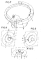
- FIG. 7 shows a perspective view similar to FIGS. 3 to 6, however, in the process chamber 1, a second embodiment a sample chamber 3 is provided: As shown in FIGS. 8 to 10 can be seen more clearly on a larger scale acts it is in this sample chamber 3 to an approximately helical Embodiment, so that a wedge-shaped and curved running Sample cavity 4 is created, which is tapered against the direction of movement of the sample chamber 3. The movement of the sample chamber 3 takes place in a viewing direction according to FIGS. 7 to 9 in the counterclockwise direction, see FIG that initially arrived in the sample cavity 4 material always deeper into the ever smaller sample cavity 4 is compressed and compressed in this way.
- the sample chamber 3 of this second embodiment is preferably movable in two directions of movement: either back and forth rotatory, so that by a movement in the Clockwise the emptying of the sample chamber by a kind Stripping effect in addition to supporting that the sample chamber opened by appropriate downward rotation can be.
- the aforementioned provided axial mobility of a guide rod be such that the distance between the sample chamber 3 and the wall 2 is changeable. This allows both the compaction as well as the emptying process facilitates or improves become.
- the part of the sample chamber is 3, which of the wall 2 - which also in this Embodiment partially formed by the insert 5 is closest - for a mechanical cleaning of the Window 8 suitable because the sample chamber 3 in its movement the window 8 sweeps over.
- the compression of the material sample to be examined to achieve that the window 8 in the sample cavity 4 is moved into it.
- optical conductor 7 may be provided that optical conductor 7 to move longitudinally. Even without elastic Design of the sample chamber 3 can be comparable Statements of quality control are achieved.
Landscapes
- Life Sciences & Earth Sciences (AREA)
- Physics & Mathematics (AREA)
- Health & Medical Sciences (AREA)
- Chemical & Material Sciences (AREA)
- Analytical Chemistry (AREA)
- Biochemistry (AREA)
- General Health & Medical Sciences (AREA)
- General Physics & Mathematics (AREA)
- Immunology (AREA)
- Pathology (AREA)
- Hydrology & Water Resources (AREA)
- Optical Measuring Cells (AREA)
Applications Claiming Priority (2)
| Application Number | Priority Date | Filing Date | Title |
|---|---|---|---|
| DE2003158135 DE10358135A1 (de) | 2003-12-12 | 2003-12-12 | Verfahren und Vorrichtung zur Qualitätsbestimmung granulatförmigen Materials |
| DE10358135 | 2003-12-12 |
Publications (1)
| Publication Number | Publication Date |
|---|---|
| EP1541995A1 true EP1541995A1 (fr) | 2005-06-15 |
Family
ID=34485334
Family Applications (1)
| Application Number | Title | Priority Date | Filing Date |
|---|---|---|---|
| EP04028818A Withdrawn EP1541995A1 (fr) | 2003-12-12 | 2004-12-06 | Procédé et appareil pour la détermination de la qualitè des matériaux granulaire |
Country Status (2)
| Country | Link |
|---|---|
| EP (1) | EP1541995A1 (fr) |
| DE (1) | DE10358135A1 (fr) |
Cited By (1)
| Publication number | Priority date | Publication date | Assignee | Title |
|---|---|---|---|---|
| US8468642B2 (en) | 2008-03-13 | 2013-06-25 | Mettler-Toledo Autochem, Inc. | Window scraper for an optical instrument |
Citations (4)
| Publication number | Priority date | Publication date | Assignee | Title |
|---|---|---|---|---|
| DE4443268A1 (de) * | 1993-12-07 | 1995-06-08 | Japan Res & Dev Ass | Vorrichtung zum Bilden von Pulverproben |
| JPH07218403A (ja) * | 1994-02-02 | 1995-08-18 | Nisshin Flour Milling Co Ltd | 粉体の色彩計用サンプル調整装置 |
| JPH09292331A (ja) * | 1996-04-26 | 1997-11-11 | Satake Eng Co Ltd | 粉体成分測定装置 |
| DE19645923A1 (de) * | 1996-11-07 | 1998-05-14 | Bayer Ag | Vorrichtung zur Bestimmung der Produktfeuchte und der Korngröße in einer Wirbelschicht |
Family Cites Families (5)
| Publication number | Priority date | Publication date | Assignee | Title |
|---|---|---|---|---|
| US4180331A (en) * | 1976-04-19 | 1979-12-25 | Bindicator Company | Method and apparatus for sampling and measuring a characteristic of flowing granular material |
| GB2150917B (en) * | 1983-12-07 | 1986-08-28 | Ranks Hovis Mcdougall Plc | Sampling and testing particulate material |
| DE3441856C2 (de) * | 1984-04-19 | 1987-04-30 | Gebrüder Bühler AG, Uzwil | Verfahren zum laufenden quantitativen Bestimmen von Inhaltsstoffen, insbesondere von Proteinen und Wasser, in mehlförmigen oder anderen Nahrungsmittel-Mahlgütern durch Infrarotmessung und Vorrichtung zur Durchführung dieses Verfahrens |
| CA2194534A1 (fr) * | 1997-01-07 | 1998-07-07 | Maztech Microvision Ltd. | Methode et appareil pour quantifier des matieres particulaires |
| DE19714115C2 (de) * | 1997-04-05 | 1999-12-23 | Bran & Luebbe | Vorrichtung zur optischen Bestimmung von Inhaltsstoffen eines rieselfähigen Gutes |
-
2003
- 2003-12-12 DE DE2003158135 patent/DE10358135A1/de not_active Ceased
-
2004
- 2004-12-06 EP EP04028818A patent/EP1541995A1/fr not_active Withdrawn
Patent Citations (4)
| Publication number | Priority date | Publication date | Assignee | Title |
|---|---|---|---|---|
| DE4443268A1 (de) * | 1993-12-07 | 1995-06-08 | Japan Res & Dev Ass | Vorrichtung zum Bilden von Pulverproben |
| JPH07218403A (ja) * | 1994-02-02 | 1995-08-18 | Nisshin Flour Milling Co Ltd | 粉体の色彩計用サンプル調整装置 |
| JPH09292331A (ja) * | 1996-04-26 | 1997-11-11 | Satake Eng Co Ltd | 粉体成分測定装置 |
| DE19645923A1 (de) * | 1996-11-07 | 1998-05-14 | Bayer Ag | Vorrichtung zur Bestimmung der Produktfeuchte und der Korngröße in einer Wirbelschicht |
Non-Patent Citations (2)
| Title |
|---|
| PATENT ABSTRACTS OF JAPAN vol. 1995, no. 11 26 December 1995 (1995-12-26) * |
| PATENT ABSTRACTS OF JAPAN vol. 1998, no. 03 27 February 1998 (1998-02-27) * |
Cited By (1)
| Publication number | Priority date | Publication date | Assignee | Title |
|---|---|---|---|---|
| US8468642B2 (en) | 2008-03-13 | 2013-06-25 | Mettler-Toledo Autochem, Inc. | Window scraper for an optical instrument |
Also Published As
| Publication number | Publication date |
|---|---|
| DE10358135A1 (de) | 2005-07-21 |
Similar Documents
| Publication | Publication Date | Title |
|---|---|---|
| EP1931953B1 (fr) | Dispositif de dosage pour substances pulverulentes ou pateuses | |
| DE3237999C2 (fr) | ||
| DE69730619T2 (de) | Siebvorrichtung | |
| DE4443268A1 (de) | Vorrichtung zum Bilden von Pulverproben | |
| EP0265597B1 (fr) | Appareil de remplissage de récipients avec des doses déterminées de produits liquides ou pâteux | |
| DE3441856C2 (de) | Verfahren zum laufenden quantitativen Bestimmen von Inhaltsstoffen, insbesondere von Proteinen und Wasser, in mehlförmigen oder anderen Nahrungsmittel-Mahlgütern durch Infrarotmessung und Vorrichtung zur Durchführung dieses Verfahrens | |
| DE2201896B1 (de) | Vorrichtung zur entnahme von einzelproben aus ruhendem schuettgut | |
| EP1381850B1 (fr) | Procede et dispositif d'analyse de cereales | |
| DE102009012444A1 (de) | Vorrichtung und Verfahren zum Filtern einer Flüssigkeit | |
| DE2449251C3 (de) | Vorrichtung zur Entnahme von Pulverproben | |
| EP2307136A1 (fr) | Récipient destiné à recevoir des échantillons de laboratoire, et utilisation d'un dispositif pour obtenir des échantillons | |
| EP0736370B1 (fr) | Appareil de déshydratation de matériaux | |
| EP1541995A1 (fr) | Procédé et appareil pour la détermination de la qualitè des matériaux granulaire | |
| DE102006049423A1 (de) | Vorrichtung zur repräsentativen Probenentnahme von rieselfähige Produkten über eine definierte Zeitdauer | |
| DE4006970A1 (de) | Vorrichtung zur reinigung von abwasser | |
| WO2006032246A2 (fr) | Dispositif et procede de determination d'un parametre d'objets | |
| DE3407646A1 (de) | Vorrichtung zur entnahme von materialproben | |
| DE10230461B4 (de) | Brecher zum Zerkleinern von sperrigem Gut | |
| DE102011001129A1 (de) | Dosiervorrichtung zur Dosierung von Mikrotabletten und Globuli | |
| DE69321517T2 (de) | Verfahren und Einheit zur automatischen Analyse der physikalisch-chemischen Parameter einer Stichprobe von Früchten | |
| DE4138456C2 (de) | Vorrichtung zur Aufbereitung von Bodenproben | |
| DE102008007818A1 (de) | Presse für Biostoffe | |
| DE3816687C2 (fr) | ||
| DE4345322C2 (de) | Vorrichtung zum Verdichten von zu kleinen Partikeln zerkleinertem Altpapier | |
| DE102005042149B4 (de) | Vorrichtung zum Bestimmen des Feuchtegehaltes einer durch zumindest eine Leitung geführten Materialschüttung |
Legal Events
| Date | Code | Title | Description |
|---|---|---|---|
| PUAI | Public reference made under article 153(3) epc to a published international application that has entered the european phase |
Free format text: ORIGINAL CODE: 0009012 |
|
| AK | Designated contracting states |
Kind code of ref document: A1 Designated state(s): AT BE BG CH CY CZ DE DK EE ES FI FR GB GR HU IE IS IT LI LT LU MC NL PL PT RO SE SI SK TR |
|
| AX | Request for extension of the european patent |
Extension state: AL BA HR LV MK YU |
|
| 17P | Request for examination filed |
Effective date: 20050623 |
|
| AKX | Designation fees paid |
Designated state(s): AT BE BG CH CY CZ DE DK EE ES FI FR GB GR HU IE IS IT LI LT LU MC NL PL PT RO SE SI SK TR |
|
| 17Q | First examination report despatched |
Effective date: 20070209 |
|
| RAP1 | Party data changed (applicant data changed or rights of an application transferred) |
Owner name: L. B. BOHLE MASCHINEN + VERFAHREN GMBH |
|
| STAA | Information on the status of an ep patent application or granted ep patent |
Free format text: STATUS: THE APPLICATION IS DEEMED TO BE WITHDRAWN |
|
| 18D | Application deemed to be withdrawn |
Effective date: 20100701 |