EP1542243A2 - Magnetkreis mit gegenüberliegenden Permanentmagneten - Google Patents
Magnetkreis mit gegenüberliegenden Permanentmagneten Download PDFInfo
- Publication number
- EP1542243A2 EP1542243A2 EP04029217A EP04029217A EP1542243A2 EP 1542243 A2 EP1542243 A2 EP 1542243A2 EP 04029217 A EP04029217 A EP 04029217A EP 04029217 A EP04029217 A EP 04029217A EP 1542243 A2 EP1542243 A2 EP 1542243A2
- Authority
- EP
- European Patent Office
- Prior art keywords
- permanent magnet
- opposing
- coercive force
- permanent
- magnetic circuit
- Prior art date
- Legal status (The legal status is an assumption and is not a legal conclusion. Google has not performed a legal analysis and makes no representation as to the accuracy of the status listed.)
- Granted
Links
Images

Classifications
-
- G—PHYSICS
- G01—MEASURING; TESTING
- G01R—MEASURING ELECTRIC VARIABLES; MEASURING MAGNETIC VARIABLES
- G01R33/00—Arrangements or instruments for measuring magnetic variables
- G01R33/20—Arrangements or instruments for measuring magnetic variables involving magnetic resonance
- G01R33/28—Details of apparatus provided for in groups G01R33/44 - G01R33/64
- G01R33/38—Systems for generation, homogenisation or stabilisation of the main or gradient magnetic field
- G01R33/383—Systems for generation, homogenisation or stabilisation of the main or gradient magnetic field using permanent magnets
-
- H—ELECTRICITY
- H01—ELECTRIC ELEMENTS
- H01F—MAGNETS; INDUCTANCES; TRANSFORMERS; SELECTION OF MATERIALS FOR THEIR MAGNETIC PROPERTIES
- H01F7/00—Magnets
- H01F7/02—Permanent magnets [PM]
- H01F7/0273—Magnetic circuits with PM for magnetic field generation
- H01F7/0278—Magnetic circuits with PM for magnetic field generation for generating uniform fields, focusing, deflecting electrically charged particles
-
- H—ELECTRICITY
- H01—ELECTRIC ELEMENTS
- H01F—MAGNETS; INDUCTANCES; TRANSFORMERS; SELECTION OF MATERIALS FOR THEIR MAGNETIC PROPERTIES
- H01F1/00—Magnets or magnetic bodies characterised by the magnetic materials therefor; Selection of materials for their magnetic properties
- H01F1/01—Magnets or magnetic bodies characterised by the magnetic materials therefor; Selection of materials for their magnetic properties of inorganic materials
- H01F1/03—Magnets or magnetic bodies characterised by the magnetic materials therefor; Selection of materials for their magnetic properties of inorganic materials characterised by their coercivity
- H01F1/032—Magnets or magnetic bodies characterised by the magnetic materials therefor; Selection of materials for their magnetic properties of inorganic materials characterised by their coercivity of hard-magnetic materials
- H01F1/04—Magnets or magnetic bodies characterised by the magnetic materials therefor; Selection of materials for their magnetic properties of inorganic materials characterised by their coercivity of hard-magnetic materials metals or alloys
- H01F1/047—Alloys characterised by their composition
- H01F1/053—Alloys characterised by their composition containing rare earth metals
- H01F1/055—Alloys characterised by their composition containing rare earth metals and magnetic transition metals, e.g. SmCo5
- H01F1/057—Alloys characterised by their composition containing rare earth metals and magnetic transition metals, e.g. SmCo5 and IIIa elements, e.g. Nd2Fe14B
Definitions
- the present invention relates to magnetic circuits with opposing permanent magnets, and specifically relates to magnetic circuits with opposing permanent magnets suitable for magnetic resonance imaging apparatuses (also referred to MRI) which obtain images of bodies by utilizing magnetic resonance.
- magnetic resonance imaging apparatuses also referred to MRI
- magnet opposing-type magnetic circuits include permanent magnet units and a yoke for allowing a magnetic flux from the magnets to pass therethrough, and generally also include pole pieces that are preferably made of soft magnetic material such as soft iron, provided on surfaces of the permanent magnet units in order to generate a uniform magnetic field in the gap between the permanent magnet units.
- Japanese Patent Provisional Publication No. 2000-51175 A, Japanese Patent Provisional Publication No. H8-339916/1996 A, all of which are herein incorporated by reference, and the like teach a method for assembling such magnetic circuits with opposing permanent magnets.
- a permanent magnet unit is arranged on a base yoke in a plate-shaped, disk-shaped or the like, followed by arranging a pole piece on an upper face of the permanent magnet unit.
- the permanent magnet Before the pole piece is arranged on the permanent magnet unit, the permanent magnet is very susceptible to a self-generated magnetic field (demagnetization field). Therefore, if the coercive force of the permanent magnet is weak, then magnetism may be reduced due to the demagnetization field, resulting in reduction of the magnetic field generated by the permanent magnet, and there is a possibility that the obtained magnetic field will be less than the design value even after a pole piece is arranged.
- the permanent magnet used in the magnetic circuit it has been necessary to use a permanent magnet whose coercive force is sufficiently high.
- special materials and technologies are required for manufacturing a magnet having a high coercive force.
- Nd 2 Fe 14 B-based rare earth magnets are used as the permanent magnets for magnetic circuits with opposing permanent magnets currently widely used.
- further adding elements such as Dy and Tb is required in order to raise the coercive force of these magnets.
- the use of these added elements causes an increase in the cost of the magnet, resulting in an increase in costs of the magnetic circuit.
- a magnetic circuit with opposing permanent magnets comprising: a pair of permanent magnet units opposing each other across a gap, the pair of permanent magnets being magnetized in thickness direction, wherein each of the permanent magnet units comprises at least two types of permanent magnet pieces with different coercive forces, and wherein, the permanent magnet piece that receives the largest demagnetization force when the permanent magnet units are manufactured has a larger coercive force than at least one other type of the permanent magnet piece; a yoke magnetically coupled to the permanent magnet units, and provided outside of the permanent magnet units and the gap; and a pair of pole pieces each arranged on a gap side of an opposing surface of each of the permanent magnet units and having a peripheral projection in opposing direction.
- magnets whose magnetism is not reduced by an demagnetization field before the pole piece is arranged during assembly of the magnetic circuit namely magnets having high coercive forces
- the strength of the demagnetization field is dependent on its position.
- the demagnetization field is particularly strong at a position in the vicinity of its center.
- the present invention defines the region which demands a magnet having high coercive force, and an inexpensive magnet having a low coercive force can be used in the other regions.
- an inexpensive magnet having a low coercive force can be used in the other regions.
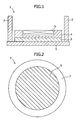
- FIG. 1 shows a schematic view of a permanent magnet opposing-type magnetic circuit, according to an embodiment of the present invention.
- FIG. 1 shows only the lower portion of the permanent magnet opposing-type magnetic circuit, since generally, an upper portion and a lower portion of the permanent magnet opposing-type magnetic circuit can be symmetrical. However, even if the upper and lower portions are asymmetric, the present invention can be applied if the configuration is the same. As shown in FIG.
- a permanent magnet opposing-type magnetic circuit 1 includes a pair of permanent magnet units 2 opposing each other across a gap and magnetized in the thickness direction, a yoke 3 magnetically coupled to the permanent magnet units and provided outside of the permanent magnet units and the gap, and a pair of pole pieces 4 arranged on a gap side of an opposing surface of each of the permanent magnet units and having a peripheral projection in opposing direction.
- a permanent magnet opposing-type magnetic circuit 1 includes a pair of permanent magnet units opposing each other across a gap and magnetized in the thickness direction to form the principal magnetic field in the gap.
- the direction of magnetization of the permanent magnet units is substantially perpendicular to the faces of the opposing permanent magnet units (thickness direction), and generally points in the same direction.
- the shape of the permanent magnet units may be round or square, for example, and although it is not a specific limitation, it is preferable that the permanent magnet units have the same shape as the pole pieces.
- the permanent magnet unit according to the present invention comprises at least two types of permanent magnet pieces with different coercive forces.
- the permanent magnet unit according to the present invention has a region of relatively high coercive force (also referred to as a high coercive force region), and a region of relatively low coercive force (also referred to as a low coercive force region). It is preferable that each of the at least two types of permanent magnets is arranged depending on the degree of the demagnetization force that each permanent magnet piece will receive during manufacture of the permanent magnet unit.
- the permanent magnet piece that receives the large demagnetization force has a larger coercive force than at least one other type of the permanent magnet piece during manufacture of the permanent magnet unit.
- the permanent magnet unit according to the present invention can be manufactured without substantial reduction in magnetism caused by the demagnetization field, because the permanent magnet piece that receives relatively large demagnetization force has high coercive force.
- the permanent magnet unit since the permanent magnet piece that receives relatively low demagnetization force has a low coercive force, there is no necessity to use a magnet whose coercive force is high and which requires special materials or technology when manufacturing this permanent magnet piece, and thus the cost of the permanent magnet needed to manuf acture the magnetic circuit can be reduced.
- the high coercive force region and the low coercive force region can be determined at the design stage. It is already standard practice to use magnetic field analysis during the design, and at this time it is possible to determine the operating points of the parts of the magnet unit, namely the magnetic flux density and the demagnetization field can be determined at that position.
- the magnet unit can be designed generally so that there is no reduction in the magnetic field, provided that the operating point is above the knick point (the point at which the slope of the curve curves downward) of the BH curve of the magnet.
- the BH curve is substantially determined by the remanent flux density and coercive force of the magnet.
- the magnet of larger coercive force can withstand a higher demagnetization field.
- the operating point of the parts of the magnet unit depends on the shape of the magnet unit, and the region that receives and does not receive the high demagnetization force is substantially continuously distributed.
- the region where there is the possibility of a substantial reduction in the coercive force in case of the permanent magnet piece of the low coercive force region due to the demagnetization force received during manufacture of the permanent magnet unit, and which receives larger demagnetization field than the knick point of the magnet of small coercive force is the high coercive force region; and that the rest of the region which receives small demagnetization field is the low coercive force region.
- the low coercive force region is constituted by an inexpensive permanent magnet material that does not require special material or technology, if it does not receive smaller demagnetization field than the knick point of the magnet having small coercive force, there is no possibility of a substantial loss of magnetism in the region.
- all of the at least two types of permanent magnet pieces have a coercive force that is large enough such that there is no substantial reduction in magnetism due to the demagnetization force received by the permanent magnetic pieces during manufacture of the permanent magnetic unit. It should be noted that in the specification, no substantial reduction in magnetism, means a case in which even after receiving an demagnetization force, the permanent magnet unit has a sufficiently large magnetic flux density so that the magnetic circuit can demonstrate a sufficiently large magnetic field strength, and that its function as a magnetic circuit is not lost.
- no substantial reduction in magnetism means a case in which, after receiving the demagnetization force, when the demagnetization force is eliminated, the permanent magnet unit preferably still has at least 97% of the original magnetic flux density before receiving the demagnetization force.
- FIG. 2 is a schematic view showing the high coercive force region and the low coercive force region of the permanent magnet unit according to the present invention. More specifically, as illustrated in FIG. 2, it is preferable that the region of the central portion of the permanent magnet unit is the high coercive force region, and that at least a part, and preferably the entirety of the other region is the low coercive force region. As described above, this is because the magnet receives the largest demagnetization field at the stage before the pole pieces are arranged when assembling the magnetic circuit, and the demagnetization field received at this time has a distribution, and is particularly large in the region of the central portion of the permanent magnet unit.
- the high coercive force region is preferably the central portion of the permanent magnet unit, preferably has at least 60% and less than 100% of the area of the opposing face of the permanent magnet unit, and more preferably at least 70% and at most 80% of the area of the central portion. This is because the region in this range receives a particularly large demagnetization force when manufacturing the permanent magnet unit.
- the entirety of the region other than the central portion (peripheral portion) is the low coercive force region, since this enables the maximum magnet cost reduction, however it is not necessary that the entirety of the peripheral portion is a low coercive force region, and it is possible that only a portion of the peripheral region is a low magnetic force region and the rest of the region is a high coercive force region.
- the central portion of the permanent magnet unit for example in the case of the central 60% portion of the permanent magnet unit, means a region that has 60% of the area of the permanent magnet unit, and is a similar shape as the permanent magnet unit, and has the same center of gravity as the permanent magnet unit.
- the coercive force of the permanent magnet piece of the high coercive force region satisfies Formula 1 given below, and even more preferable that it has a coercive force of at least 850 kA/m.
- the principal magnetic field has a magnetic field strength of at least 0.1 T and the permanent magnet that forms the principal magnetic field of the magnetic circuit has a remanent flux density of at least 1.2 T, when this is satisfied, there is no possibility that the magnetic field of the permanent magnet unit will be substantially reduced by the demagnetization force.
- coercive force (bHc) and the remanent flux density (Br) are measured in accordance with JIS (Japanese Industrial Standard) C 2501, and, for example, can be measured by a BH tracer.
- the coercive force of the permanent magnet piece in the low coercive force region can have any value less than the coercive force of the permanent magnet piece in the high coercive force region, without particular limitation.
- the coercive force of the low coercive force region is a coercive force of a common magnetic material that can be inexpensively obtained and whose manufacture does not demand special material or technology.
- the coercive force in the low coercive force region is at least 700 kA/m and less than the coercive force of the high coercive force region.
- the permanent magnet material suitable for the permanent magnet unit according to the present invention is a Nd 2 Fe 14 B-based rare earth permanent magnet which further contains additional element, such as dysprosium (Dy), terbium (Tb), praseodymium (Pr), gallium (Ga), molybdenum (Mo) and/or vanadium (V) in addition with the principal components. These are in order to further increase the coercive force.
- a rare earth permanent magnet such as, for example, a Nd 2 Fe 14 B-based rare earth permanent magnet
- the permanent magnet material used in the high coercive force region is a Nd 2 Fe 14 B-based rare earth permanent magnet which further contains additional element, such as dysprosium (Dy), terbium (Tb), praseodymium (Pr), gallium (Ga), molybdenum (Mo) and/or vanadium (V) in addition with the principal components. These are in order to further increase the coercive force.
- the permanent magnet material used for the low coercive force region is the magnet material described above that does not include the additional element such as Dy and Tb or those in which these element is reduced. This is because that by not including, or reducing these high priced elements it is possible to manufacture the low coercive force region at low cost.
- the permanent magnet material can be manufactured by any known method.
- a magnetic circuit with opposing permanent magnets comprises a yoke magnetically coupled to the permanent magnet units, and provided outside of the permanent magnet units and the gap.
- a closed magnetic circuit is formed.
- the yoke 3 can be the same as a conventional ones, a detailed description is hereby omitted.
- the shape of the yoke and it can be any, for example, it can be letter-C-shaped, square, or be shaped as two columns. More specifically, a pair of substantially parallel plate-shaped yokes can be supported by column-shaped yokes, and the permanent magnets can be provided on opposing faces of the plate-shaped yokes.
- a magnetic circuit with opposing permanent magnets comprises a pair of pole pieces each arranged on a gap side of an opposing surface of each of the permanent magnet units and having a peripheral projection in opposing direction.
- This improves the uniformity of the magnetic field of the magnetic circuit. Namely, if a spherical or elliptical space (also referred to as an evaluation space) is theoretically provided in the central portion of the gap, and the uniformity of the magnetic field of the magnetic circuit is evaluated according to the magnetic field distribution in the evaluation space, then when the pole pieces are simple disk-shapes, the magnetic field strength at the equatorial portion of the evaluation space is lower than at the pole portions.
- pole pieces are provided with peripheral projection, then the physical distance between the equatorial portion of the evaluation space and the peripheral projection is closer, the magnetic field strength increases at the equatorial portion, and thus the uniformity of the magnetic field improves across the entire evaluation space.
- the pole pieces 4 may be the same as conventional ones and thus a detailed description is hereby omitted.
- a plurality of small projections whose step is smaller than that of the peripheral projection can be provided on a periphery of a base portion of the pole pieces.
- a magnetic circuit with opposing permanent magnets further comprises a pair of inclined magnetic field coils 5 each arranged on a gap side of an opposing surface of each of the pole pieces and inside the peripheral projection, and opposing each other across the gap.
- the uniformity of the magnetic field of the uniform magnetic field space between the gap of the pole pieces can be intentionally, linearly disrupted by the inclined magnetic field coil.
- spatial information can also be provided when the signal is converted to an image.
- the permanent magnet unit according to the present invention can be manufactured by methods described in Japanese Patent Provisional Publication No. 2000-51175 A and Japanese Patent Provisional Publication No. H8-339916/1996 A.
- the permanent magnet unit can be configured with a plurality of permanent magnet pieces, for example cubes whose sides are in the order of 25 mm to 100 mm.
- the regions described above can be corresponded to the permanent magnet pieces as follows. Namely, the above-described regions can be set as regions occupied by permanent magnet pieces of which at least half the area of the region is occupied by the above-described regions.
- a specific permanent magnet piece is included in a specific region may be defined to mean the case in which at least half the area of the permanent magnet piece is included in the region.
- the relationship between the permanent magnet piece and the region is shown in FIG. 3.
- the central portion of the permanent magnet unit can be constituted by the high coercive force permanent magnet piece (high coercive force region 6) and the other region can be constituted by the permanent magnet piece of a low coercive force (low coercive force region 7).
- the magnetic circuit with opposing permanent magnets illustrated in FIG. 1 was used, whose magnetic field strength is 0.2 T, and whose gap between the upper and lower inclined magnetic field coils is 400 mm.
- a permanent magnet piece made from a permanent magnet material of a type shown in Table 1 below was used for the upper and lower permanent magnet units.
- the characteristics of the permanent magnet material are obtained by measuring with a sample cut from the magnet block in accordance with JIS C 2501 by a BH tracer.
- a magnet circuit constituted by a high coercive force type magnet in 70% of the central portion of the permanent magnet units and a normal type in the rest of the region was used.
- a magnetic circuit in which the entire region of the permanent magnet units is constituted by a high coercive force type magnet was used as Comparative Example 1
- a magnet in which the entire region of the permanent magnet unit is constituted by a normal type magnet was used as Comparative Example 2.
- Table 2 shows the magnetic field strength (T) and the cost of the magnets necessary to constitute magnetic circuits of Working Example 1 and of Comparative Examples 1 and 2, wherein the cost of Comparative Example 1 is given as 100.
- Magnetic field strength of the magnetic circuit were measured at a position at the center of the gap using a METROLAB NMR Tesla Meter PT2025. Magnetic field strength of the magnetic circuits Configuration Magnetic field strength (T) Magnet cost Comparative Example 1 High coercive force type only 0.2030 100 Working Example 1 High coercive force type in 70% of center portion, normal type elsewhere 0.2035 96 Comparative Example 2 Normal type only 0.1852 90
- the cost of the magnet can be reduced by 4%, compared to that of the permanent magnet unit whose entire region is constituted by a magnet whose coercive force is high, and it is possible to generate a magnetic field strength of the same level as that of the permanent magnet unit whose entire region is constituted by magnet whose coercive force is high.
Landscapes
- Physics & Mathematics (AREA)
- Condensed Matter Physics & Semiconductors (AREA)
- General Physics & Mathematics (AREA)
- Electromagnetism (AREA)
- Engineering & Computer Science (AREA)
- Power Engineering (AREA)
- Magnetic Resonance Imaging Apparatus (AREA)
- Permanent Field Magnets Of Synchronous Machinery (AREA)
- Hard Magnetic Materials (AREA)
- Non-Reversible Transmitting Devices (AREA)
- Coils Or Transformers For Communication (AREA)
Applications Claiming Priority (2)
| Application Number | Priority Date | Filing Date | Title |
|---|---|---|---|
| JP2003414031A JP4139767B2 (ja) | 2003-12-12 | 2003-12-12 | 永久磁石対向型磁気回路 |
| JP2003414031 | 2003-12-12 |
Publications (3)
| Publication Number | Publication Date |
|---|---|
| EP1542243A2 true EP1542243A2 (de) | 2005-06-15 |
| EP1542243A3 EP1542243A3 (de) | 2007-12-26 |
| EP1542243B1 EP1542243B1 (de) | 2011-03-02 |
Family
ID=34510549
Family Applications (1)
| Application Number | Title | Priority Date | Filing Date |
|---|---|---|---|
| EP04029217A Ceased EP1542243B1 (de) | 2003-12-12 | 2004-12-09 | Magnetkreis mit gegenüberliegenden Permanentmagneten |
Country Status (5)
| Country | Link |
|---|---|
| US (1) | US6924722B2 (de) |
| EP (1) | EP1542243B1 (de) |
| JP (1) | JP4139767B2 (de) |
| CN (1) | CN100522050C (de) |
| DE (1) | DE602004031585D1 (de) |
Cited By (1)
| Publication number | Priority date | Publication date | Assignee | Title |
|---|---|---|---|---|
| EP2450918A3 (de) * | 2010-11-05 | 2015-11-25 | Shin-Etsu Chemical Co., Ltd. | Dipolring-Magnetkreis |
Families Citing this family (5)
| Publication number | Priority date | Publication date | Assignee | Title |
|---|---|---|---|---|
| CN100415162C (zh) * | 2005-03-09 | 2008-09-03 | Ge医疗系统环球技术有限公司 | 磁体系统和磁共振成像系统 |
| US7851958B2 (en) * | 2006-06-12 | 2010-12-14 | Remy International, Inc. | Electric machine with interior permanent magnets |
| CN100581454C (zh) | 2006-07-14 | 2010-01-20 | Ge医疗系统环球技术有限公司 | 磁场发生器和mri装置 |
| CN101388271A (zh) * | 2007-09-14 | 2009-03-18 | Ge医疗系统环球技术有限公司 | 磁体系统和mri设备 |
| JP2020008421A (ja) * | 2018-07-07 | 2020-01-16 | Tdk株式会社 | 磁気センサ |
Family Cites Families (7)
| Publication number | Priority date | Publication date | Assignee | Title |
|---|---|---|---|---|
| US4401960A (en) * | 1979-12-18 | 1983-08-30 | Kanetsu Kogyo Kabushiki Kaisha | Magnet assembly |
| US4675609A (en) * | 1985-09-18 | 1987-06-23 | Fonar Corporation | Nuclear magnetic resonance apparatus including permanent magnet configuration |
| EP0262880B1 (de) * | 1986-09-27 | 1992-06-10 | Sumitomo Special Metals Co. Ltd. | Vorrichtung zur Erzeugung eines Magnetfeldes für rechnergesteuerte Tomographie mittels magnetischer Kernresonanz |
| US5200001A (en) * | 1989-12-01 | 1993-04-06 | Sumitomo Special Metals Co., Ltd. | Permanent magnet |
| US5055812A (en) | 1990-09-24 | 1991-10-08 | The United States Of America As Represented By The Secretary Of The Army. | Compensation for magnetic nonuniformities of permanent magnet structures |
| JP3016545B2 (ja) | 1995-06-12 | 2000-03-06 | 信越化学工業株式会社 | 永久磁石磁気回路 |
| JP2953659B1 (ja) | 1998-08-06 | 1999-09-27 | 住友特殊金属株式会社 | Mri用磁界発生装置およびその組立方法並びにそれに用いる磁石ユニットの組立方法 |
-
2003
- 2003-12-12 JP JP2003414031A patent/JP4139767B2/ja not_active Expired - Fee Related
-
2004
- 2004-12-08 US US11/006,874 patent/US6924722B2/en not_active Expired - Fee Related
- 2004-12-09 DE DE602004031585T patent/DE602004031585D1/de not_active Expired - Lifetime
- 2004-12-09 EP EP04029217A patent/EP1542243B1/de not_active Ceased
- 2004-12-13 CN CNB2004101011156A patent/CN100522050C/zh not_active Expired - Fee Related
Cited By (1)
| Publication number | Priority date | Publication date | Assignee | Title |
|---|---|---|---|---|
| EP2450918A3 (de) * | 2010-11-05 | 2015-11-25 | Shin-Etsu Chemical Co., Ltd. | Dipolring-Magnetkreis |
Also Published As
| Publication number | Publication date |
|---|---|
| CN1626033A (zh) | 2005-06-15 |
| US6924722B2 (en) | 2005-08-02 |
| JP4139767B2 (ja) | 2008-08-27 |
| DE602004031585D1 (de) | 2011-04-14 |
| EP1542243A3 (de) | 2007-12-26 |
| EP1542243B1 (de) | 2011-03-02 |
| CN100522050C (zh) | 2009-08-05 |
| US20050128036A1 (en) | 2005-06-16 |
| JP2005168854A (ja) | 2005-06-30 |
Similar Documents
| Publication | Publication Date | Title |
|---|---|---|
| JP5242960B2 (ja) | 温度操作方法 | |
| US5252924A (en) | Magnetic field generating apparatus for MRI | |
| JPH0831635A (ja) | Mri用磁界発生装置 | |
| WO1993018707A1 (fr) | Generateur de champ magnetique destine a l'imagerie par resonance magnetique_____________________________________________________ | |
| US20150213944A1 (en) | Reactor | |
| WO2001069276A3 (en) | Coil configuration for nmr imaging and method of detecting magnetic fields in nmr imaging | |
| WO1998007362A3 (en) | Planar open magnet MRI system | |
| US6924722B2 (en) | Magnetic circuit with opposing permanent magnets | |
| US5363078A (en) | Homogeneous field magnet having pole shoes with pole piece means which are spaced over a correction air gap | |
| JP2561591B2 (ja) | Mri用磁界発生装置 | |
| JPH08335511A (ja) | 永久磁石磁気回路 | |
| De Campos et al. | Comparative view of coercivity mechanisms in soft and hard magnetic materials | |
| US6838966B2 (en) | Circular pole piece and MRI system | |
| JP2005237501A (ja) | 磁気回路および磁気回路磁界調整方法 | |
| EP0541872A1 (de) | Apparat zur Erzeugung von Magnetfeldern für die Bildgebung mittels magnetischer Resonanz | |
| JP4783564B2 (ja) | 磁気共鳴イメージング・システム向けの極片を製作するためのシステム及び方法 | |
| US6933820B2 (en) | Magnetic circuit with opposing permanent magnets and method for adjusting magnetic field thereof | |
| JPH11204330A (ja) | 電磁アクチュエータ | |
| USRE35565E (en) | Magnetic field generating apparatus for MRI | |
| JPH04138131A (ja) | Mri用磁界発生装置 | |
| JP4218762B2 (ja) | 磁場中熱処理装置 | |
| JPS62139304A (ja) | 磁界均一性のよい磁気回路 | |
| JPH0956692A (ja) | 磁石対向型永久磁石磁気回路とその磁場調整方法 | |
| JP3445303B2 (ja) | Mri用磁界発生装置 | |
| JP2011187815A (ja) | 釈放形電磁石装置およびその釈放形電磁石装置を用いた開閉装置 |
Legal Events
| Date | Code | Title | Description |
|---|---|---|---|
| PUAI | Public reference made under article 153(3) epc to a published international application that has entered the european phase |
Free format text: ORIGINAL CODE: 0009012 |
|
| AK | Designated contracting states |
Kind code of ref document: A2 Designated state(s): AT BE BG CH CY CZ DE DK EE ES FI FR GB GR HU IE IS IT LI LT LU MC NL PL PT RO SE SI SK TR |
|
| AX | Request for extension of the european patent |
Extension state: AL BA HR LV MK YU |
|
| PUAL | Search report despatched |
Free format text: ORIGINAL CODE: 0009013 |
|
| AK | Designated contracting states |
Kind code of ref document: A3 Designated state(s): AT BE BG CH CY CZ DE DK EE ES FI FR GB GR HU IE IS IT LI LT LU MC NL PL PT RO SE SI SK TR |
|
| AX | Request for extension of the european patent |
Extension state: AL BA HR LV MK YU |
|
| 17P | Request for examination filed |
Effective date: 20080111 |
|
| 17Q | First examination report despatched |
Effective date: 20080222 |
|
| AKX | Designation fees paid |
Designated state(s): DE FR GB |
|
| GRAP | Despatch of communication of intention to grant a patent |
Free format text: ORIGINAL CODE: EPIDOSNIGR1 |
|
| RIN1 | Information on inventor provided before grant (corrected) |
Inventor name: MIYATA, KOJIC/O MAGNETIC MATERIALS RESEARCH & Inventor name: DOI, YUHITOC/O MAGNETIC MATERIALS RESEARCH & Inventor name: HIGUCHI, DAIC/O MAGNETIC MATERIALS RESEARCH & |
|
| GRAS | Grant fee paid |
Free format text: ORIGINAL CODE: EPIDOSNIGR3 |
|
| GRAA | (expected) grant |
Free format text: ORIGINAL CODE: 0009210 |
|
| AK | Designated contracting states |
Kind code of ref document: B1 Designated state(s): DE FR GB |
|
| REG | Reference to a national code |
Ref country code: GB Ref legal event code: FG4D |
|
| REF | Corresponds to: |
Ref document number: 602004031585 Country of ref document: DE Date of ref document: 20110414 Kind code of ref document: P |
|
| REG | Reference to a national code |
Ref country code: DE Ref legal event code: R096 Ref document number: 602004031585 Country of ref document: DE Effective date: 20110414 |
|
| PLBE | No opposition filed within time limit |
Free format text: ORIGINAL CODE: 0009261 |
|
| STAA | Information on the status of an ep patent application or granted ep patent |
Free format text: STATUS: NO OPPOSITION FILED WITHIN TIME LIMIT |
|
| 26N | No opposition filed |
Effective date: 20111205 |
|
| REG | Reference to a national code |
Ref country code: DE Ref legal event code: R097 Ref document number: 602004031585 Country of ref document: DE Effective date: 20111205 |
|
| REG | Reference to a national code |
Ref country code: FR Ref legal event code: PLFP Year of fee payment: 12 |
|
| REG | Reference to a national code |
Ref country code: FR Ref legal event code: PLFP Year of fee payment: 13 |
|
| REG | Reference to a national code |
Ref country code: FR Ref legal event code: PLFP Year of fee payment: 14 |
|
| PGFP | Annual fee paid to national office [announced via postgrant information from national office to epo] |
Ref country code: FR Payment date: 20181120 Year of fee payment: 15 Ref country code: GB Payment date: 20181205 Year of fee payment: 15 |
|
| GBPC | Gb: european patent ceased through non-payment of renewal fee |
Effective date: 20191209 |
|
| PG25 | Lapsed in a contracting state [announced via postgrant information from national office to epo] |
Ref country code: GB Free format text: LAPSE BECAUSE OF NON-PAYMENT OF DUE FEES Effective date: 20191209 Ref country code: FR Free format text: LAPSE BECAUSE OF NON-PAYMENT OF DUE FEES Effective date: 20191231 |
|
| PGFP | Annual fee paid to national office [announced via postgrant information from national office to epo] |
Ref country code: DE Payment date: 20201124 Year of fee payment: 17 |
|
| REG | Reference to a national code |
Ref country code: DE Ref legal event code: R119 Ref document number: 602004031585 Country of ref document: DE |
|
| PG25 | Lapsed in a contracting state [announced via postgrant information from national office to epo] |
Ref country code: DE Free format text: LAPSE BECAUSE OF NON-PAYMENT OF DUE FEES Effective date: 20220701 |