EP1542345B1 - Kleinstaktuator mit Direktantrieb und Herstellungsverfahren für denselben - Google Patents
Kleinstaktuator mit Direktantrieb und Herstellungsverfahren für denselben Download PDFInfo
- Publication number
- EP1542345B1 EP1542345B1 EP04257631A EP04257631A EP1542345B1 EP 1542345 B1 EP1542345 B1 EP 1542345B1 EP 04257631 A EP04257631 A EP 04257631A EP 04257631 A EP04257631 A EP 04257631A EP 1542345 B1 EP1542345 B1 EP 1542345B1
- Authority
- EP
- European Patent Office
- Prior art keywords
- section
- stator
- micro
- rotor
- beams
- Prior art date
- Legal status (The legal status is an assumption and is not a legal conclusion. Google has not performed a legal analysis and makes no representation as to the accuracy of the status listed.)
- Expired - Lifetime
Links
- 238000000034 method Methods 0.000 title claims description 5
- 230000005291 magnetic effect Effects 0.000 claims description 31
- 239000003302 ferromagnetic material Substances 0.000 claims description 9
- 238000005452 bending Methods 0.000 claims description 6
- 238000004080 punching Methods 0.000 claims description 6
- 238000005530 etching Methods 0.000 claims description 4
- 238000003825 pressing Methods 0.000 claims description 4
- 230000005611 electricity Effects 0.000 claims description 3
- 229910052751 metal Inorganic materials 0.000 claims description 3
- 239000002184 metal Substances 0.000 claims description 3
- 230000007704 transition Effects 0.000 claims description 3
- 230000001939 inductive effect Effects 0.000 claims description 2
- 238000005516 engineering process Methods 0.000 description 5
- 230000004907 flux Effects 0.000 description 3
- 229910000831 Steel Inorganic materials 0.000 description 2
- 238000013461 design Methods 0.000 description 2
- 229920006332 epoxy adhesive Polymers 0.000 description 2
- 230000001965 increasing effect Effects 0.000 description 2
- 238000011160 research Methods 0.000 description 2
- 239000004065 semiconductor Substances 0.000 description 2
- 238000005549 size reduction Methods 0.000 description 2
- 239000010959 steel Substances 0.000 description 2
- 238000003466 welding Methods 0.000 description 2
- RYGMFSIKBFXOCR-UHFFFAOYSA-N Copper Chemical compound [Cu] RYGMFSIKBFXOCR-UHFFFAOYSA-N 0.000 description 1
- 238000004026 adhesive bonding Methods 0.000 description 1
- 238000011949 advanced processing technology Methods 0.000 description 1
- 230000000694 effects Effects 0.000 description 1
- 230000005489 elastic deformation Effects 0.000 description 1
- 230000002708 enhancing effect Effects 0.000 description 1
- 230000001747 exhibiting effect Effects 0.000 description 1
- 230000005294 ferromagnetic effect Effects 0.000 description 1
- 238000005304 joining Methods 0.000 description 1
- 238000004519 manufacturing process Methods 0.000 description 1
- 239000000463 material Substances 0.000 description 1
- 229910001172 neodymium magnet Inorganic materials 0.000 description 1
- 230000003287 optical effect Effects 0.000 description 1
- 229910052761 rare earth metal Inorganic materials 0.000 description 1
- 150000002910 rare earth metals Chemical class 0.000 description 1
- 238000012827 research and development Methods 0.000 description 1
- 229910001285 shape-memory alloy Inorganic materials 0.000 description 1
- 238000007493 shaping process Methods 0.000 description 1
- 238000005476 soldering Methods 0.000 description 1
- 239000010409 thin film Substances 0.000 description 1
- 238000013519 translation Methods 0.000 description 1
- 230000001960 triggered effect Effects 0.000 description 1
Images



Classifications
-
- H—ELECTRICITY
- H02—GENERATION; CONVERSION OR DISTRIBUTION OF ELECTRIC POWER
- H02K—DYNAMO-ELECTRIC MACHINES
- H02K33/00—Motors with reciprocating, oscillating or vibrating magnet, armature or coil system
- H02K33/02—Motors with reciprocating, oscillating or vibrating magnet, armature or coil system with armatures moved one way by energisation of a single coil system and returned by mechanical force, e.g. by springs
- H02K33/04—Motors with reciprocating, oscillating or vibrating magnet, armature or coil system with armatures moved one way by energisation of a single coil system and returned by mechanical force, e.g. by springs wherein the frequency of operation is determined by the frequency of uninterrupted AC energisation
- H02K33/06—Motors with reciprocating, oscillating or vibrating magnet, armature or coil system with armatures moved one way by energisation of a single coil system and returned by mechanical force, e.g. by springs wherein the frequency of operation is determined by the frequency of uninterrupted AC energisation with polarised armatures
-
- H—ELECTRICITY
- H01—ELECTRIC ELEMENTS
- H01F—MAGNETS; INDUCTANCES; TRANSFORMERS; SELECTION OF MATERIALS FOR THEIR MAGNETIC PROPERTIES
- H01F7/00—Magnets
- H01F7/06—Electromagnets; Actuators including electromagnets
- H01F2007/068—Electromagnets; Actuators including electromagnets using printed circuit coils
-
- H—ELECTRICITY
- H01—ELECTRIC ELEMENTS
- H01F—MAGNETS; INDUCTANCES; TRANSFORMERS; SELECTION OF MATERIALS FOR THEIR MAGNETIC PROPERTIES
- H01F7/00—Magnets
- H01F7/06—Electromagnets; Actuators including electromagnets
- H01F7/08—Electromagnets; Actuators including electromagnets with armatures
- H01F7/121—Guiding or setting position of armatures, e.g. retaining armatures in their end position
- H01F7/122—Guiding or setting position of armatures, e.g. retaining armatures in their end position by permanent magnets
-
- H—ELECTRICITY
- H01—ELECTRIC ELEMENTS
- H01F—MAGNETS; INDUCTANCES; TRANSFORMERS; SELECTION OF MATERIALS FOR THEIR MAGNETIC PROPERTIES
- H01F7/00—Magnets
- H01F7/06—Electromagnets; Actuators including electromagnets
- H01F7/08—Electromagnets; Actuators including electromagnets with armatures
- H01F7/14—Pivoting armatures
Definitions
- This invention relates to a small-size direct-acting actuator.
- the recent advance of the semiconductor fabrication technology has made it possible to construct ultra-fine structures of the micrometer order. Triggered by the advanced processing technology, efforts are being made on the research and development of so-called micro-machines.
- the actuator which is one of elemental devices of the micro-machine is of great concern.
- the microactuator is generally divided into rotary and direct-acting types. Since the direct-acting type has a very simple structure, most research works address direct-acting actuators. From the driving principle, the microactuator is generally divided into electrostatic, piezoelectric, electromagnetic, shape-memory alloy, photo-drive, and pneumatic drive modes. Of these, the electrostatic mode is most attractive, and the piezoelectric mode next.
- the electromagnetic mode actuator is considered in itself to be one of most attractive actuators because high efficiency and high output are expected from its principle, and they have been utilized in the prior art motor technology. Nevertheless, there are few research reports relating to direct-acting microactuators of the electromagnetic mode. One main reason is the difficulty of size reduction due to complex structure.
- Components of the electromagnetic direct-acting microactuator include a permanent magnet and a coil.
- the permanent magnet magnet materials exhibiting high performance despite small size have been developed by virtue of the advanced thin-film or miniaturization technology.
- the coil small size coils have been developed as a result of the progress of micro-electromechanical systems utilizing the semiconductor micropatterning technology.
- a voice coil motor is one of the linear drive electromagnetic actuators which have been widely used.
- an operating or rotor section is generally provided with a linear guide for preventing the operating section from deviating from the drive direction.
- the linear guide has a guide rail and a slider which are movably combined via a bearing.
- the slider can serve as a rotor.
- linear guides using ball bearings linear guides having a slider with plane dimensions of at least 3 mm x 6 mm are now commercially available.
- the guide rail used therein has a size which is the sum of the size of the slider, the stroke, and the size of an attachment to a stationary section (stator).
- the actuator has a size of 1 cm or larger.
- a pneumatic bearing is of the design that a rod-shaped slider is movably inserted into an axial through-hole in a quadrangular prism or cylindrical guide rail. This design further increases the size of the actuator since the guide rail should have a sufficient length relative to the diameter of the rod-shaped slider so as to prevent the slider from becoming loose in the guide rail.
- JP2002-200460 discloses a vibration actuator with a fixed part and a vibrating part having a plurality of magnets and yokes to close the magnetic flux of the plurality of magnets, and a plurality of elastic members to hold the vibration part to the fixed part so that it can be vibrated by supplying current to a coil which interlinks with the magnetic flux generated by the magnets.
- EP 1 091 477 describes a vibration generator including a movable element with a permanent magnet attached thereto; a stationary element having end faces which oppose, across prescribed gaps, respective ones of end faces of the movable element, the stationary element being excited by passing a current through an attached coil to form a magnetic path with the movable element ; and resilient support members for supporting the movable element so that the movable element can vibrate in a direction in which the stationary element is magnetised by the coil.
- US 6,317,277 relates to an optical pickup device with a compact actuator, which has a holder including an objective lens supported flexible by a base and a hole. Focussing and tracking coils are attached to at least a portion of the hole. A magnetic circuit that imparts magnetic flux to the focussing and tracking coils is placed in the hole. Movement in focussing and tracking directions is effected by electric current passing through the coils.
- An object of the invention is to provide a direct-acting actuator which has a simple structure and small size in that a rotor is supported for swing motion by micro-beams that undergo elastic deformation only in the drive direction, rather than a linear guide and a corresponding method of forming an actuator. This is achieved by an actuator according to claim 1 and a corresponding method according to claim 1.
- the small-size direct-acting actuator herein preferably has a width of 1 to 10 mm, a length of 1 to 10 mm, and a height of 0.1 to 5 mm. It comprises a stator section, an attachment section secured to the stator section, metallic micro-beams extending from the attachment section and shaped by bending, a rotor section supported for swing motion by the micro-beams, a permanent magnet disposed in the stator or rotor section, and a coil disposed in the rotor or stator section. When electric current is conducted through the coil in the magnetic field created by the permanent magnet the micro-beams are caused to be displaced for inducing swing motion of the rotor section.
- a pair of the micro-beams are disposed at opposite sides of the stator section for supporting the rotor section, and the micro-beams are flexible enough to be displaced by a drive force developed between the stator and rotor sections in a drive direction which is parallel to a plane sandwiched between the pair of micro-beams and perpendicular to the longitudinal direction of the micro-beams, but highly stiff in other directions.
- Each micro-beam includes at least one fold, preferably at least one doubled ( ⁇ 180°) fold.
- the micro-beams are formed integrally with the attachment section and the rotor section by punching and bending a metal plate, preferably having a gage of 0.025 to 0.5 mm.
- the stator section is made of a ferromagnetic material.
- the rotor section is made of a ferromagnetic material.
- the actuator may further include an auxiliary yoke opposed to the stator section for forming a magnetic circuit, with the rotor section being interposed between the auxiliary yoke and the stator section.
- an aspect herein provides a small-size direct-acting actuator having a width of 1 to 10 mm, a length of 1 to 10 mm, and a height of 0.1 to 5 mm, comprising a stator section where a permanent magnet or a coil is disposed, and a member comprising a stator attachment section, micro-beams, and a rotor section where a coil or a permanent magnet is disposed, the permanent magnet and the stator section forming a magnetic circuit, the permanent magnet and the coil being opposed to define a small gap therebetween and within the magnetic circuit, and the micro-beams being juxtaposed and integrally formed at laterally opposed edges of the stator attachment section and standing along the edges at right angles toward the stator section so that the micro-beams are formed from elongated strips extending from a front side of the attachment section at opposed edges, the strips being folded at an angle of 180° to form a first fold, then at a further angle of 180° at a position backward of the attachment section front side
- the member including the stator attachment section, micro-beams and rotor section is prepared by furnishing a blank in which the attachment section and the rotor section are bridged at laterally opposed sides by strips, folding inside the strips at a first intermediate point an angle of about 180° so that the rotor section overlies the attachment section, then folding back the strips at a second intermediate point an angle of about 180° so that the rear edge of the rotor section is situated close to the front edge of the attachment section, and finally folding the strips along their longitudinal inner side at right angles toward the stator section.
- a direct-acting actuator of a simple structure and small size is available using the electromagnetic mode featuring high efficiency and outputs. It may be other than a disc-drive actuator.
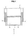
- FIGS. 1 and 2 are plan and perspective exploded views of a direct-acting actuator 2 according to one embodiment of the invention, respectively. For the sake of clarity, wires for supplying electric power to a coil are not shown.
- the actuator 2 includes a stator section or member 16, a member 14, and an optional yoke 20.
- the member 14 includes a stator attachment section 6, micro-beams 8, 10, and a rotor section 12. Attached to the rotor section 12 is a coil 4. Disposed in the stator section 16 is a permanent magnet 18.
- the stator section 16 is preferably made of a ferromagnetic material for helping form a magnetic circuit.
- the auxiliary yoke 20 made of a ferromagnetic material may be attached, if necessary, for enhancing the efficiency of the magnetic circuit.
- the member 14 (which includes the stator attachment section 6, the micro-beams 8, 10, and the rotor section 12), the stator section 16, and the auxiliary yoke 20 are assembled and secured to an apparatus that carries the actuator (not shown) by usual joining means such as adhesive bonding or welding.
- an object (not shown) to be arcuately moved is mounted to the rotor section 12 by any desired means.
- the micro-beams 8 and 10 are juxtaposed and integrally formed at laterally opposed edges of the stator attachment section 6 and stand along the edges at right angles toward the stator section 16. More specifically, as described later in conjunction with FIG.
- the micro-beams 8 and 10 are formed by furnishing elongated strips 8a, 10a extending forward from the front side of the stator attachment section 6 at opposed edges, folding the strips 8a, 10a inside an angle of 180° to form a first fold, then folding the strips inside an angle of 180° at a position backward of the attachment section front side to form a second fold (in the reverse direction to the first fold) and provide the last portions of the strips 8a, 10a which extend forward again.
- the rotor section 12 is integrally formed through transition portions 8b, 10b with the last forward extending portions of the strips 8a, 10a.
- the permanent magnet 18 and the coil 4 secured to the rotor section 12 are opposed to maintain a small gap therebetween.
- the permanent magnet 18 is magnetized in a direction perpendicular to the plane of the opposed coil, to provide two magnetic poles which are laterally arranged as viewed in the direction of arrow Y in FIG. 1 .
- two singularly magnetized permanent magnets may be juxtaposed.
- the permanent magnet 18 is dimensioned to a magnetic pole area of 0.4 to 10 mm 2 and a thickness of 0.1 to 1 mm in the magnetizing direction.
- the permanent magnet 18 creates magnetic forces which largely affect the drive force of the direct-acting actuator 2 of the invention.
- the use of high strength rare earth magnets, typically Nd-Fe-B sintered magnets is preferred.
- the stator section 16 and the auxiliary yoke 20 are made of a ferromagnetic material such as steel and have a gage of about 0.05 to 0.25 mm.
- the permanent magnet 18 is secured to the stator section 16 by bonding with an epoxy adhesive, soldering, welding or the like.
- the coil 4 is made using a copper wire or a printed wiring board.
- the coil 4 is wound so as to generate at its center a magnetic field perpendicular to the magnetic pole plane of the opposed permanent magnet 18.
- a multilayer wiring board may be used depending on the necessary magnetic force or drive force.
- the coil 4 is secured to the rotor section 12 using an epoxy adhesive or the like. Power supply lines (not shown) to the coil 4 are secured to the stator attachment section 6 and the like while it is kept loose so as not to interfere with swing motion of the direct-acting actuator.
- the member 14 including the stator attachment section 6, micro-beams 8, 10 and rotor section 12 is made of a steel-base flat spring and has a gage of about 0.025 to 0.3 mm. It is preferable to use non-ferromagnetic steel for the purpose of not disturbing the magnetic fields produced by the magnetic circuit (16, 18, 20) and the coil 4.
- a pair of micro-beams 8, 10 are extended from the stator attachment section 6 toward the rotor section 12, once folded back toward the stator attachment section 6, and folded again toward the rotor section 12 where they support the rotor section 12.
- This double-folded structure exerts the same effect as the arrangement of three beams on each side, that is, provides increased resilience in the drive direction of the direct-acting actuator and maintains high stiffness against back and forth motion in a vertical direction, as compared with a single beam.
- the number of folds may be only one or three or more.
- the drive of the direct-acting actuator of the invention is of the same basic structure as ordinary voice coil motors.
- the rotor section 12 is arcuately moved by Lorentz forces in the direction of arrow X.
- the micro-beams 8, 10 are prepared by punching out a thin blank by pressing or etching, followed by bending.
- FIG. 4 illustrates the working and shaping process.
- the member 14 including the stator attachment section 6, micro-beams 8, 10 and rotor section 12 is prepared by first punching a configured blank 14' out of a thin plate by pressing or etching, the blank 14' being configured such that the stator attachment section 6 and the rotor section 12 are bridged or connected at laterally opposed sides by side strips 8a, 10a as shown in FIG. 4a .
- the side strips 8a, 10a at first intermediate points depicted by line A are folded an angle of about 180° as shown by arrow B, so that the rotor section 12 overlies the attachment section 6 as shown in FIG.
- the order of folding is not limited to the above embodiment.
- the side strips may be previously provided with notches at fold lines to facilitate successive working steps.
- stator section 16 and the auxiliary yoke 20 are prepared by punching out a thin blank by pressing or etching, followed by bending.
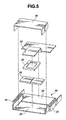
- FIG. 5 is a perspective exploded view of the direct-acting actuator according to a second embodiment of the invention.
- a coil 24 is disposed in a stator section 22, and a permanent magnet 28 is disposed in a rotor section 26. Since the coil 24 from which a power supply wire extends is placed in the stator section 22 which is stationary, the wiring is simplified.
- a member 36 including a stator attachment section 30, micro-beams 32, 34 and a rotor section 26 is made of a ferromagnetic material for increasing the efficiency of the magnetic circuit.
- a plate yoke (not shown) made of a ferromagnetic material may be disposed between the permanent magnet 28 and the rotor section 26.
- an auxiliary yoke 38 is mounted to the rotor section 26 so as to enclose the stator section 22, coil 24 and permanent magnet 28.
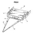
- FIG. 6 is a perspective view of an electromagnetic manipulator to which the inventive actuator is applied
- FIG. 7 is a perspective exploded view of the manipulator.
- the electromagnetic manipulator 40 includes a pair of hands 42, 44 and a direct-acting actuator.
- One hand 42 is secured to the stator attachment section 6.
- the second hand 44 is secured to the rotor section 12. Only the second hand 44 can be moved arcuately to clamp an object of 0.2 mm or less between the hands.
- the manipulator in the illustrated embodiment is dimensioned to a length of 13 mm, a width of 6 mm and a height of 1 mm, which is only a fraction of prior art known piezoelectric and photo-drive manipulators, for example, having a length of 45 mm, a width of 32 mm and a height of 10 mm.
Landscapes
- Engineering & Computer Science (AREA)
- Power Engineering (AREA)
- Reciprocating, Oscillating Or Vibrating Motors (AREA)
Claims (7)
- Aktuator (2), umfassend:einen Statorabschnitt (16),einen Befestigungsabschnitt (6), der an dem Statorabschnitt (16) befestigt ist,metallische Mikroträger (8, 10), die sich von dem Befestigungsabschnitt wegerstrecken und durch Biegen geformt sind, wobei jeder der Mikroträger zumindest einen Umschlag umfasst,einen Rotorabschnitt (12), der für eine Schwingbewegung durch die Mikroträger getragen wird,einen Permanentmagneten (18), der in dem Stator- oder Rotorabschnitt angeordnet ist undeine Spule (4), die in dem Rotor- oder Statorabschnitt angeordnet ist;wobei ein Paar der Mikroträger (8, 10) an gegenüberliegenden Seiten des Statorabschnitts (16) angeordnet ist, um den Rotorabschnitt (12) zu tragen, und die Mikroträger (8, 10) ausreichend biegbar sind, um durch eine zwischen dem Stator- und dem Rotorabschnitt erzeugte Antriebskraft in eine Antriebsrichtung verschoben zu werden, die im rechten Winkel auf die Längsrichtung der Mikroträger und parallel zu einer deren Längsrichtungen enthaltenden Ebene verläuft, aber in anderen Richtungen sehr steif sind,
wobei, wenn elektrischer Strom durch die Spule (4) in dem durch den Permanentmagneten (18) erzeugten Magnetfeld geleitet wird, eine Verschiebung der Mikroträger (8, 10) bewirkt wird, wodurch die Schwingbewegung des Rotorabschnitts (12) erzeugt wird;
dadurch gekennzeichnet, dass:der Aktuator (2) ein kleiner direktbetätigter Aktuator ist, um einen an dem Rotorabschnitt (12) angebrachten Gegenstand bogenförmig zu bewegen, wobei der Aktuator (2) eine Breite von 1 bis 10 mm, eine Länge von 1 bis 10 mm und eine Höhe von 0,1 bis 5 mm aufweist, wobei die Mikroträger (8, 10) durch Stanzen und Biegen einer Metallplatte einstückig mit dem Befestigungsabschnitt (6) und dem Rotorabschnitt (12) ausgebildet sind;und wobei das Element (14), das den Statorbefestigungsabschnitt (6), die Mikroträger (8, 10) und den Rotorabschnitt (12) umfasst, aus einem Rohling (14') hergestellt wurde, in dem der Befestigungsabschnitt (6) und der Rotorabschnitt (12) an seitlich gegenüberliegenden Seiten durch Streifen (8a, 10a) verbunden sind, indem die Streifen an einem ersten Zwischenpunkt in einem Winkel von etwa 180° so nach innen umgeschlagen werden, dass der Rotorabschnitt (12) über dem Befestigungsabschnitt (6) liegt, die Streifen dann an einem zweiten Zwischenpunkt in einem Winkel von etwa 180° nach so zurück umgeschlagen werden, d ass der hintere Rand des Rotorabschnitts (12) nahe des vorderen Rands des Befestigungsabschnitts (6) angeordnet ist, und schließlich die Streifen (8a, 10a) entlang ihrer Längsinnenseite im rechten Winkel in Richtung des Statorabschnitts (16) umgeschlagen werden. - Aktuator nach Anspruch 1, worin die Metallplatte eine Stärke von 0,025 bis 0,5 mm aufweist.
- Aktuator nach einem der Ansprüche 1 oder 2, worin der Statorabschnitt (16) aus einem ferromagnetischen Material besteht.
- Aktuator nach einem der Ansprüche 1 bis 3, worin der Rotorabschnitt (12) aus einem ferromagnetischen Material besteht.
- Aktuator nach einem der Ansprüche 1 bis 4, ferner umfassend ein Hilfsjoch (20), das dem Statorabschnitt (16) gegenüberliegt, um einen Magnetkreis auszubilden, wobei der Rotorabschnitt (12) zwischen dem Hilfsjoch (20) und dem Statorabschnitt (16) angeordnet ist.
- Kleiner direktbetätigter Aktuator (2) nach Anspruch 1, wobei der Permanentmagnet (18) und der Statorabschnitt (16) einen Magnetkreis ausbilden, wobei der Permanentmagnet (18) und die Spule (4) einander gegenüberliegen, um einen kleinen Spalt zwischen einander und innerhalb des Magnetkreises zu definieren, und die Mikroträger (8, 10) nebeneinander angeordnet und an seitlich gegenüberliegenden Rändern des Statorbefestigungsabschnitts (6) einstückig ausgebildet sind und entlang der Ränder im rechten Winkel in Richtung des Statorabschnitts (16) stehen, sodass die Mikroträger aus länglichen Streifen (8a, 10a) ausgebildet sind, die sich von einer Vorderseite des Befestigungsabschnitts an gegenüberliegenden Rändern erstrecken, wobei die Streifen in einem Winkel von 180° nach innen umgeschlagen sind, um einen ersten Umschlag auszubilden, dann in einem weiteren Winkel von 180° in einer Position hinter der Vorderseite des Befestigungsabschnitts zur Ausbildung eines zweiten Umschlags umgeschlagen sind und letzte Abschnitt der Streifen (8a, 10a) bereitstellen, die sich nach vorne erstrecken; und der Rotorabschnitt (12) einstückig ausgebildet ist und über Übergangsabschnitte (8b, 10b) mit den letzten Abschnitten (8a, 10a) der Streifen verbunden sind,
wobei der Rotorabschnitt (12), wenn Elektrizität durch die Spule (4) in dem durch den Permanentmagneten (18) erzeugten Magnetfeld geleitet wird, durch Lorentz-Kräfte bogenförmig in eine seitliche Richtung bewegbar ist. - Verfahren zur Ausbildung eines Aktuators nach einem der vorangegangenen Ansprüche, worin ein Element (14), das den Statorbefestigungsabschnitt (6), Mikroträger (8, 10) und den Rotorabschnitt (18) umfasst, dadurch hergestellt wird, dass zunächst durch Pressen oder Ätzen ein konfigurierter Rohling (14') aus einer dünnen Platte hergestellt wird, wobei der Rohling (14') so ausgebildet wird, dass der Statorbefestigungsabschnitt (6) und der Rotorabschnitt (12) an seitlich gegenüberliegenden Seiten durch Seitenstreifen (8a, 10a) verbunden werden, die Seitenstreifen (8a, 10a) an ersten Zwischenpunkten (A) in einem Winkel von etwa 180° so umgeschlagen sind, dass der Rotorabschnitt (12) über dem Befestigungsabschnitt (6) liegt, dann die Seitenstreifen (8a, 10a) an zweiten Zwischenpunkten (C) in einem Winkel von etwa 180° so zurück umgeschlagen werden, dass der hinter Rand des Rotorabschnitts (6) nahe des vorderen Rands des Befestigungsabschnitts (6) angeordnet ist, und schließlich die Seitenstreifen (8a, 10a) entlang ihrer Längsinnenseite im rechten Winkel umgeschlagen werden, wodurch ein Paar Mikroträger (8, 10) ausgebildet wird, die sich von dem Statorbefestigungsabschnitt (6) in Richtung des Rotorabschnitts (12) erstrecken, ein Mal in Richtung des Statorbefestigungsabschnitts (6) zurück umgeschlagen werden und dann wieder in Richtung des Rotorabschnitts (12) umgeschlagen werden, wo sie den Rotorabschnitt (12) tragen, wobei die Mikroträger (8, 10) ausreichend biegbar sind, um durch eine zwischen dem Stator- und dem Rotorabschnitt erzeugte Antriebskraft in eine Antriebsrichtung verschoben zu werden, die parallel zu der Ebene der Längsrichtung der Mikroträger (8, 10) und im rechten Winkel auf deren Längsrichtung verläuft, aber in anderen Richtungen sehr steif sind.
Applications Claiming Priority (2)
| Application Number | Priority Date | Filing Date | Title |
|---|---|---|---|
| JP2003408859 | 2003-12-08 | ||
| JP2003408859 | 2003-12-08 |
Publications (3)
| Publication Number | Publication Date |
|---|---|
| EP1542345A2 EP1542345A2 (de) | 2005-06-15 |
| EP1542345A3 EP1542345A3 (de) | 2006-05-17 |
| EP1542345B1 true EP1542345B1 (de) | 2010-04-21 |
Family
ID=34510465
Family Applications (1)
| Application Number | Title | Priority Date | Filing Date |
|---|---|---|---|
| EP04257631A Expired - Lifetime EP1542345B1 (de) | 2003-12-08 | 2004-12-08 | Kleinstaktuator mit Direktantrieb und Herstellungsverfahren für denselben |
Country Status (3)
| Country | Link |
|---|---|
| US (1) | US7355305B2 (de) |
| EP (1) | EP1542345B1 (de) |
| DE (1) | DE602004026674D1 (de) |
Cited By (1)
| Publication number | Priority date | Publication date | Assignee | Title |
|---|---|---|---|---|
| DE102013110029C5 (de) * | 2013-09-12 | 2017-03-16 | Bürkert Werke GmbH | Elektrodynamischer Aktor |
Families Citing this family (50)
| Publication number | Priority date | Publication date | Assignee | Title |
|---|---|---|---|---|
| US7355305B2 (en) * | 2003-12-08 | 2008-04-08 | Shen-Etsu Chemical Co., Ltd. | Small-size direct-acting actuator |
| US10831093B1 (en) | 2008-05-19 | 2020-11-10 | Spatial Cam Llc | Focus control for a plurality of cameras in a smartphone |
| US12425739B2 (en) | 2020-09-29 | 2025-09-23 | Peter Lablans | Camera digital gimbal system |
| DE202008016518U1 (de) | 2008-12-12 | 2009-02-26 | Bürkert Werke GmbH & Co.KG | Elektromagnetischer Aktor |
| KR20100116335A (ko) * | 2009-04-22 | 2010-11-01 | 엘지이노텍 주식회사 | 선형 진동기 |
| US9553497B2 (en) | 2009-07-22 | 2017-01-24 | Mplus Co., Ltd. | Horizontal linear vibrator |
| KR101156780B1 (ko) * | 2009-07-22 | 2012-06-18 | 삼성전기주식회사 | 수평 리니어 진동자 |
| KR101064469B1 (ko) * | 2010-04-05 | 2011-09-15 | 엘지이노텍 주식회사 | 진동 모터 |
| KR101796094B1 (ko) * | 2010-09-01 | 2017-11-09 | 주식회사 이엠텍 | 수평 진동 모터 |
| KR101259683B1 (ko) * | 2010-10-27 | 2013-05-02 | 엘지이노텍 주식회사 | 수평 진동 모터 |
| US8878401B2 (en) * | 2010-11-10 | 2014-11-04 | Lg Innotek Co., Ltd. | Linear vibrator having a trembler with a magnet and a weight |
| KR101255914B1 (ko) * | 2010-12-31 | 2013-04-23 | 삼성전기주식회사 | 선형 진동모터 |
| US9710061B2 (en) | 2011-06-17 | 2017-07-18 | Apple Inc. | Haptic feedback device |
| US9594429B2 (en) | 2014-03-27 | 2017-03-14 | Apple Inc. | Adjusting the level of acoustic and haptic output in haptic devices |
| US10133351B2 (en) | 2014-05-21 | 2018-11-20 | Apple Inc. | Providing haptic output based on a determined orientation of an electronic device |
| US9886090B2 (en) | 2014-07-08 | 2018-02-06 | Apple Inc. | Haptic notifications utilizing haptic input devices |
| CN104467340B (zh) * | 2014-09-30 | 2017-02-01 | 浙江省东阳市诚基电机有限公司 | 一种水平振动马达 |
| US20170024010A1 (en) | 2015-07-21 | 2017-01-26 | Apple Inc. | Guidance device for the sensory impaired |
| CN205081655U (zh) * | 2015-10-15 | 2016-03-09 | 瑞声光电科技(常州)有限公司 | 双谐振振动电机 |
| CN205081657U (zh) * | 2015-10-23 | 2016-03-09 | 瑞声光电科技(常州)有限公司 | 振动电机 |
| US10772394B1 (en) | 2016-03-08 | 2020-09-15 | Apple Inc. | Tactile output for wearable device |
| US10585480B1 (en) | 2016-05-10 | 2020-03-10 | Apple Inc. | Electronic device with an input device having a haptic engine |
| US9829981B1 (en) | 2016-05-26 | 2017-11-28 | Apple Inc. | Haptic output device |
| US10649529B1 (en) | 2016-06-28 | 2020-05-12 | Apple Inc. | Modification of user-perceived feedback of an input device using acoustic or haptic output |
| US10845878B1 (en) | 2016-07-25 | 2020-11-24 | Apple Inc. | Input device with tactile feedback |
| US10372214B1 (en) | 2016-09-07 | 2019-08-06 | Apple Inc. | Adaptable user-selectable input area in an electronic device |
| JP2018137919A (ja) * | 2017-02-22 | 2018-08-30 | 日本電産セイミツ株式会社 | 振動モータ |
| US10437359B1 (en) | 2017-02-28 | 2019-10-08 | Apple Inc. | Stylus with external magnetic influence |
| CN207074948U (zh) * | 2017-04-14 | 2018-03-06 | 瑞声科技(新加坡)有限公司 | 振动器件 |
| CN206834956U (zh) * | 2017-04-14 | 2018-01-02 | 瑞声科技(新加坡)有限公司 | 线性振动电机 |
| CN207098908U (zh) * | 2017-04-14 | 2018-03-13 | 瑞声科技(新加坡)有限公司 | 振动器件 |
| US10775889B1 (en) | 2017-07-21 | 2020-09-15 | Apple Inc. | Enclosure with locally-flexible regions |
| US10768747B2 (en) | 2017-08-31 | 2020-09-08 | Apple Inc. | Haptic realignment cues for touch-input displays |
| US11054932B2 (en) | 2017-09-06 | 2021-07-06 | Apple Inc. | Electronic device having a touch sensor, force sensor, and haptic actuator in an integrated module |
| US10556252B2 (en) | 2017-09-20 | 2020-02-11 | Apple Inc. | Electronic device having a tuned resonance haptic actuation system |
| US10768738B1 (en) | 2017-09-27 | 2020-09-08 | Apple Inc. | Electronic device having a haptic actuator with magnetic augmentation |
| US11258343B2 (en) * | 2018-05-21 | 2022-02-22 | Apple Inc. | Double helix actuator with magnetic sections having alternating polarities |
| US10942571B2 (en) | 2018-06-29 | 2021-03-09 | Apple Inc. | Laptop computing device with discrete haptic regions |
| US10936071B2 (en) | 2018-08-30 | 2021-03-02 | Apple Inc. | Wearable electronic device with haptic rotatable input |
| US10613678B1 (en) | 2018-09-17 | 2020-04-07 | Apple Inc. | Input device with haptic feedback |
| US10966007B1 (en) | 2018-09-25 | 2021-03-30 | Apple Inc. | Haptic output system |
| KR102138339B1 (ko) * | 2018-10-24 | 2020-07-27 | 주식회사 엠플러스 | 사운드 진동 액츄에이터 |
| CN113396019B (zh) * | 2019-03-12 | 2022-06-28 | 阿尔卑斯阿尔派株式会社 | 电磁驱动装置以及操作装置 |
| US20230012628A1 (en) * | 2019-12-11 | 2023-01-19 | Lofelt Gmbh | Linear vibration actuator having moving coil and moving magnet |
| JP7404515B2 (ja) * | 2020-04-23 | 2023-12-25 | アルプスアルパイン株式会社 | 振動発生装置 |
| US11024135B1 (en) | 2020-06-17 | 2021-06-01 | Apple Inc. | Portable electronic device having a haptic button assembly |
| US11831215B2 (en) * | 2021-05-06 | 2023-11-28 | Aac Microtech (Changzhou) Co., Ltd. | Linear vibration motor |
| JP2023006567A (ja) * | 2021-06-30 | 2023-01-18 | ミネベアミツミ株式会社 | 振動装置 |
| FR3130091B1 (fr) * | 2021-12-02 | 2025-02-14 | Commissariat Energie Atomique | Transducteur électromagnétique pour la récupération d’énergie vibratoire |
| JP2024113572A (ja) * | 2023-02-09 | 2024-08-22 | アルプスアルパイン株式会社 | 振動発生装置及び振動発生装置の製造方法 |
Family Cites Families (16)
| Publication number | Priority date | Publication date | Assignee | Title |
|---|---|---|---|---|
| JP3969780B2 (ja) * | 1997-03-19 | 2007-09-05 | 松下電器産業株式会社 | 振動発生方法 |
| US5893283A (en) * | 1997-05-07 | 1999-04-13 | Mas-Hamilton Group | Solenoid controlled bolt control for an electronic lock |
| JP2000011408A (ja) | 1998-06-24 | 2000-01-14 | Pioneer Electron Corp | ディスクプレーヤのピックアップ装置 |
| US6414823B1 (en) * | 1999-06-09 | 2002-07-02 | Seagate Technology Llc | Coil-structures for magnetic microactuator |
| US6262500B1 (en) | 1999-10-05 | 2001-07-17 | Teikoku Tsushin Kogyo Co., Ltd. | Vibration generator |
| JP2001340812A (ja) * | 2000-05-30 | 2001-12-11 | Nidec Copal Corp | 振動発生器 |
| JP3855738B2 (ja) | 2000-11-06 | 2006-12-13 | ソニー株式会社 | 振動アクチュエータと振動アクチュエータを有する電子機器 |
| JP3494981B2 (ja) * | 2000-11-20 | 2004-02-09 | 帝国通信工業株式会社 | 振動発生器 |
| US6583524B2 (en) * | 2001-03-07 | 2003-06-24 | Hewlett-Packard Company | Micro-mover with balanced dynamics |
| JP2003010783A (ja) * | 2001-06-29 | 2003-01-14 | Sumida Technologies Inc | リニア振動モータ(2) |
| DE10225024A1 (de) * | 2002-06-06 | 2003-12-24 | Braun Gmbh | Antriebseinrichtung zur Erzeugung einer oszillierenden Bewegung für ein elektrisches Kleingerät |
| CN100416658C (zh) * | 2002-06-26 | 2008-09-03 | 新科实业有限公司 | 具有较低刚度悬挂设计的配置金属框架压电微致动器 |
| JP4583715B2 (ja) * | 2003-01-08 | 2010-11-17 | 信越化学工業株式会社 | 磁気ヘッド用サスペンション |
| US6879468B2 (en) * | 2003-01-08 | 2005-04-12 | Shin-Etsu Chemical Co., Ltd. | Magnetic head actuator having an improved microactuator oscillatably supported by metallic micro-beams |
| US7333298B2 (en) * | 2003-12-08 | 2008-02-19 | Shin-Etsu Chemical Co., Ltd. | Magnetic head actuator and magnetic disk drive using the same |
| US7355305B2 (en) * | 2003-12-08 | 2008-04-08 | Shen-Etsu Chemical Co., Ltd. | Small-size direct-acting actuator |
-
2004
- 2004-12-07 US US11/004,859 patent/US7355305B2/en not_active Expired - Fee Related
- 2004-12-08 DE DE602004026674T patent/DE602004026674D1/de not_active Expired - Lifetime
- 2004-12-08 EP EP04257631A patent/EP1542345B1/de not_active Expired - Lifetime
Cited By (2)
| Publication number | Priority date | Publication date | Assignee | Title |
|---|---|---|---|---|
| DE102013110029C5 (de) * | 2013-09-12 | 2017-03-16 | Bürkert Werke GmbH | Elektrodynamischer Aktor |
| US10396646B2 (en) | 2013-09-12 | 2019-08-27 | Buerkert Werke Gmbh | Micro value comprising an electrodynamic actuator having stationary magnet arrangement and a moveable air-core coil |
Also Published As
| Publication number | Publication date |
|---|---|
| EP1542345A2 (de) | 2005-06-15 |
| DE602004026674D1 (de) | 2010-06-02 |
| US7355305B2 (en) | 2008-04-08 |
| EP1542345A3 (de) | 2006-05-17 |
| US20050121984A1 (en) | 2005-06-09 |
Similar Documents
| Publication | Publication Date | Title |
|---|---|---|
| EP1542345B1 (de) | Kleinstaktuator mit Direktantrieb und Herstellungsverfahren für denselben | |
| US11025149B2 (en) | Linear vibration motor and electronic device | |
| US8044541B2 (en) | Multi-degree-of-freedom actuator and stage device | |
| US20190314860A1 (en) | Linear vibration motor | |
| CN115149767B (zh) | 电磁驱动可调刚度纳米定位平台 | |
| TW201136107A (en) | Linear motor | |
| JP3302777B2 (ja) | 可動磁石式アクチュエータ | |
| JP4756916B2 (ja) | 振動波モータ | |
| JP4407818B2 (ja) | 小型直動型アクチュエータ | |
| CN117335633A (zh) | 具有内嵌柔顺机构的法应力电磁致动器 | |
| JP2011200752A (ja) | 振動モータ | |
| CN103503299B (zh) | 惯性驱动促动器 | |
| US20250047161A1 (en) | Vibration generating device, and production method therefor | |
| JP4041261B2 (ja) | ワイヤ放電加工機 | |
| JP5269009B2 (ja) | 駆動装置 | |
| EP3326276B1 (de) | Transversalfluss-linearmotor | |
| EP2290661A2 (de) | Stellantrieb | |
| JP5088536B2 (ja) | 可動コイル型リニアモータの組立方法 | |
| KR20050085223A (ko) | 구동장치 | |
| JP2005218203A (ja) | アクチュエータ及びボンディング装置 | |
| EP1542208A1 (de) | Magnetkopf Aktuator und Plattenlaufwerk welcher dieses benützt | |
| JP5851210B2 (ja) | 慣性駆動アクチュエータ | |
| JP4602888B2 (ja) | 振動発生装置 | |
| JP3268101B2 (ja) | 位置決め装置 | |
| KR101085461B1 (ko) | 이종 탄성부재를 이용한 소형 액츄에이터 장치 |
Legal Events
| Date | Code | Title | Description |
|---|---|---|---|
| PUAI | Public reference made under article 153(3) epc to a published international application that has entered the european phase |
Free format text: ORIGINAL CODE: 0009012 |
|
| AK | Designated contracting states |
Kind code of ref document: A2 Designated state(s): AT BE BG CH CY CZ DE DK EE ES FI FR GB GR HU IE IS IT LI LT LU MC NL PL PT RO SE SI SK TR |
|
| AX | Request for extension of the european patent |
Extension state: AL BA HR LV MK YU |
|
| PUAL | Search report despatched |
Free format text: ORIGINAL CODE: 0009013 |
|
| AK | Designated contracting states |
Kind code of ref document: A3 Designated state(s): AT BE BG CH CY CZ DE DK EE ES FI FR GB GR HU IE IS IT LI LT LU MC NL PL PT RO SE SI SK TR |
|
| AX | Request for extension of the european patent |
Extension state: AL BA HR LV MK YU |
|
| 17P | Request for examination filed |
Effective date: 20060807 |
|
| AKX | Designation fees paid |
Designated state(s): DE FR GB |
|
| 17Q | First examination report despatched |
Effective date: 20070510 |
|
| GRAP | Despatch of communication of intention to grant a patent |
Free format text: ORIGINAL CODE: EPIDOSNIGR1 |
|
| RTI1 | Title (correction) |
Free format text: SMALL-SIZE DIRECT-ACTING ACTUATOR AND CORRESPONDING FORMING METHOD |
|
| GRAS | Grant fee paid |
Free format text: ORIGINAL CODE: EPIDOSNIGR3 |
|
| GRAA | (expected) grant |
Free format text: ORIGINAL CODE: 0009210 |
|
| AK | Designated contracting states |
Kind code of ref document: B1 Designated state(s): DE FR GB |
|
| REG | Reference to a national code |
Ref country code: GB Ref legal event code: FG4D |
|
| REF | Corresponds to: |
Ref document number: 602004026674 Country of ref document: DE Date of ref document: 20100602 Kind code of ref document: P |
|
| PLBE | No opposition filed within time limit |
Free format text: ORIGINAL CODE: 0009261 |
|
| STAA | Information on the status of an ep patent application or granted ep patent |
Free format text: STATUS: NO OPPOSITION FILED WITHIN TIME LIMIT |
|
| 26N | No opposition filed |
Effective date: 20110124 |
|
| REG | Reference to a national code |
Ref country code: FR Ref legal event code: PLFP Year of fee payment: 12 |
|
| REG | Reference to a national code |
Ref country code: FR Ref legal event code: PLFP Year of fee payment: 13 |
|
| PGFP | Annual fee paid to national office [announced via postgrant information from national office to epo] |
Ref country code: FR Payment date: 20161111 Year of fee payment: 13 Ref country code: DE Payment date: 20161129 Year of fee payment: 13 Ref country code: GB Payment date: 20161207 Year of fee payment: 13 |
|
| REG | Reference to a national code |
Ref country code: DE Ref legal event code: R119 Ref document number: 602004026674 Country of ref document: DE |
|
| GBPC | Gb: european patent ceased through non-payment of renewal fee |
Effective date: 20171208 |
|
| REG | Reference to a national code |
Ref country code: FR Ref legal event code: ST Effective date: 20180831 |
|
| PG25 | Lapsed in a contracting state [announced via postgrant information from national office to epo] |
Ref country code: DE Free format text: LAPSE BECAUSE OF NON-PAYMENT OF DUE FEES Effective date: 20180703 Ref country code: FR Free format text: LAPSE BECAUSE OF NON-PAYMENT OF DUE FEES Effective date: 20180102 |
|
| PG25 | Lapsed in a contracting state [announced via postgrant information from national office to epo] |
Ref country code: GB Free format text: LAPSE BECAUSE OF NON-PAYMENT OF DUE FEES Effective date: 20171208 |