EP2290661A2 - Stellantrieb - Google Patents
Stellantrieb Download PDFInfo
- Publication number
- EP2290661A2 EP2290661A2 EP10150251A EP10150251A EP2290661A2 EP 2290661 A2 EP2290661 A2 EP 2290661A2 EP 10150251 A EP10150251 A EP 10150251A EP 10150251 A EP10150251 A EP 10150251A EP 2290661 A2 EP2290661 A2 EP 2290661A2
- Authority
- EP
- European Patent Office
- Prior art keywords
- movable member
- axis
- respect
- coils
- circuit system
- Prior art date
- Legal status (The legal status is an assumption and is not a legal conclusion. Google has not performed a legal analysis and makes no representation as to the accuracy of the status listed.)
- Withdrawn
Links
- 230000004308 accommodation Effects 0.000 claims abstract description 38
- 239000004020 conductor Substances 0.000 claims description 4
- 230000005483 Hooke's law Effects 0.000 description 1
- 230000002457 bidirectional effect Effects 0.000 description 1
- 238000012986 modification Methods 0.000 description 1
- 230000004048 modification Effects 0.000 description 1
Images


Classifications
-
- H—ELECTRICITY
- H01—ELECTRIC ELEMENTS
- H01F—MAGNETS; INDUCTANCES; TRANSFORMERS; SELECTION OF MATERIALS FOR THEIR MAGNETIC PROPERTIES
- H01F7/00—Magnets
- H01F7/06—Electromagnets; Actuators including electromagnets
- H01F7/066—Electromagnets with movable winding
-
- H—ELECTRICITY
- H02—GENERATION; CONVERSION OR DISTRIBUTION OF ELECTRIC POWER
- H02K—DYNAMO-ELECTRIC MACHINES
- H02K41/00—Propulsion systems in which a rigid body is moved along a path due to dynamo-electric interaction between the body and a magnetic field travelling along the path
- H02K41/02—Linear motors; Sectional motors
- H02K41/035—DC motors; Unipolar motors
- H02K41/0352—Unipolar motors
- H02K41/0354—Lorentz force motors, e.g. voice coil motors
-
- H—ELECTRICITY
- H01—ELECTRIC ELEMENTS
- H01F—MAGNETS; INDUCTANCES; TRANSFORMERS; SELECTION OF MATERIALS FOR THEIR MAGNETIC PROPERTIES
- H01F7/00—Magnets
- H01F7/06—Electromagnets; Actuators including electromagnets
- H01F7/08—Electromagnets; Actuators including electromagnets with armatures
- H01F7/081—Magnetic constructions
-
- H—ELECTRICITY
- H01—ELECTRIC ELEMENTS
- H01F—MAGNETS; INDUCTANCES; TRANSFORMERS; SELECTION OF MATERIALS FOR THEIR MAGNETIC PROPERTIES
- H01F7/00—Magnets
- H01F7/06—Electromagnets; Actuators including electromagnets
- H01F7/08—Electromagnets; Actuators including electromagnets with armatures
- H01F7/121—Guiding or setting position of armatures, e.g. retaining armatures in their end position
- H01F7/122—Guiding or setting position of armatures, e.g. retaining armatures in their end position by permanent magnets
-
- H—ELECTRICITY
- H01—ELECTRIC ELEMENTS
- H01F—MAGNETS; INDUCTANCES; TRANSFORMERS; SELECTION OF MATERIALS FOR THEIR MAGNETIC PROPERTIES
- H01F7/00—Magnets
- H01F7/06—Electromagnets; Actuators including electromagnets
- H01F7/08—Electromagnets; Actuators including electromagnets with armatures
- H01F7/17—Pivoting and rectilinearly-movable armatures
-
- H—ELECTRICITY
- H02—GENERATION; CONVERSION OR DISTRIBUTION OF ELECTRIC POWER
- H02K—DYNAMO-ELECTRIC MACHINES
- H02K2201/00—Specific aspects not provided for in the other groups of this subclass relating to the magnetic circuits
- H02K2201/18—Machines moving with multiple degrees of freedom
Definitions
- the present invention relates to an actuator, and more particularly, to an actuator used in a photograph module.
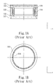
- Fig. 1A shows a cross-sectional view of a prior art actuator.
- the actuator includes a yoke 101, a pad 102, a holder 107, a movable member 105, an elastic member 106 and a magnetic circuit system.
- the magnetic circuit system comprises a magnet 103 and a coil 104.
- the coil 104 is electrically driven so that it will interact with the magnetic field of the magnet 103 to generate a force that drives the movable member 105 to move with respect to an axis (Z-axis) when a current is directed therethrough.
- the prior art actuator can cause a movement with respect to an axis, it is not capable of providing an angle of inclination with respect to any axis. Accordingly, the compensation for an angle of inclination cannot be performed. There remains a need in the art for an improved actuator to resolve the aforementioned drawback.
- One object of the present invention is to provide an improved actuator capable of causing a movement with respect to an axis and, at the same time, providing an angle of inclination with respect to at least one axis to enable the compensation for an angle of inclination.
- the present invention provides an actuator including a holder having a movable member accommodation space and at least three magnet accommodation spaces, a movable member received by the movable member accommodation space of the holder, and a magnetic circuit system comprising at least three magnets and at least three coils, the magnetic circuit system enabling the movable member to move with respect to an axis and incline at an angle with respect to at least one axis; wherein each of the at least three magnets is received by one of the at least three magnet accommodation spaces and the directions of the top and bottom magnetic poles thereof are perpendicular to the axis with respect to which the movable member moves; and wherein each of the at least three coils corresponds to one of the at least three magnets and is associated with the movable member, and the central axis of each of the at least three coils is perpendicular to the axis with respect to which the movable member moves.
- a power source is used to drive the three coils, enabling the three coils and the corresponding magnets to create a force to drive the movable member.
- the movable member can move with respect to an axis; when the currents delivered from the power source having different current values are directed to the three coils, respectively, the movable member can move with respect to an axis and incline at an angle with respect to more than one axis; when only one of the three coils is driven by the current delivered from the power source, the movable member can incline at an angle with respect to an axis; when two of the three coils are driven by the current delivered from the power source, the movable member can incline at an angle with respect to more than one axis.
- the present invention provides another actuator including: a holder having a movable member accommodation space and at least three coil accommodation spaces; a movable member received by the movable member accommodation space of the holder; and a magnetic circuit system comprising at least three magnets and at least three coils, the magnetic circuit system enabling the movable member to move with respect to an axis and incline at an angle with respect to at least one axis; wherein each of the at least three coils is received by one of the at least three coil accommodation spaces and the central axis thereof is perpendicular to the axis with respect to which the movable member moves; and wherein each of the at least three magnets corresponds to one of the at least three coils and is associated with the movable member, and the directions of the top and bottom magnetic poles thereof are perpendicular to the axis with respect to which the movable member moves.
- Fig. 2 shows a schematic perspective view of an actuator 300 in accordance with a first embodiment of the present invention.
- the actuator 300 includes a holder 301 having a moveable member accommodation space and three magnet accommodation spaces, a movable member 302 received by the moveable member accommodation space of the holder 301, an elastic member 309, and a magnetic circuit system comprising three magnets 303, 304 and 305 and three coils 306, 307 and 308 (as shown in Fig. 3 ), each of the three magnets 303, 304 and 305 being received by a corresponding one of the three magnet accommodation spaces of the holder 301; wherein the three magnet accommodation spaces of the holder 301 are evenly and symmetrically disposed around the movable member 302.
- the movable member 302 may be cylindrical in shape with the magnets 303, 304 and 305 and the coils 306, 307 and 308 evenly disposed around the circumference thereof.
- Fig. 3 shows a schematic perspective view of the magnetic circuit system of the actuator 300 shown in Fig. 2 in accordance with the first embodiment of the present invention.
- the magnetic circuit system comprises three magnets 303, 304 and 305 and three coils 306, 307 and 308 so as to form three magnet-coil sets whereby the magnetic circuit system is evenly and symmetrically disposed around the movable member 302.
- the magnetic circuit system enables the movable member 302 to move with respect to an axis and incline at an angle with respect to at least one axis.
- the first magnet-coil set comprises the magnet 303 and the coil 306;
- the second magnet-coil set comprises the magnet 304 and the coil 307;
- the third magnet-coil set comprises the magnet 305 and the coil 308.
- Each of the magnets 303, 304 and 305 is received by a corresponding one of the three magnet accommodation spaces of the holder 301.
- the directions of the top and bottom magnetic poles of the magnet are opposite and perpendicular to the axis with respect to which the movable member 302 moves, and the central axis of the coil is perpendicular to the axis with respect to which the movable member moves.
- the directions of the top and bottom magnetic poles of the magnet 304 are in the Y and -Y directions, respectively, and the central axis of the coil 307 is Y-axis.
- an electric current may, for example but not limited to, flow through the upper portion of the coil 307 in the X direction while passing through the lower portion of the coil 307 in the -X direction, such that either the upper or the lower portion of the coil 307 is acted upon by a force (Lorentz Force) in the Z direction, that is, the coil 307 moves in the Z direction.
- a force Liperentz Force
- the force further drives the movable member 302.
- a power source is used to drive the three coils, enabling the three coils and the corresponding magnets to generate a force to drive the movable member 302.
- the movable member 302 can move with respect to an axis.
- each of the three coils 305, 306 and 307 is acted upon by a force of the same magnitude in the Z direction, thereby enabling the movable member 302 to move with respect to the Z-axis.
- the movable member 302 can incline at an angle with respect to an axis.
- the coil 306 is the only one of the three coils driven by the current delivered from the power source, it is acted upon by a force in the Z direction, thereby enabling the movable member 302 to incline at an angle with respect to the X-axis.
- the movable member 302 can incline at an angle with respect to more than one axis.
- each of the coils 306 and 307 is acted upon by a force in the Z direction, thereby enabling the movable member 302 to incline at an angle with respect to the X-axis and the Y-axis at the same time.
- the movable member 302 can move with respect to an axis and incline at an angle with respect to more than one axis.
- each of the coils 305, 306 and 307 is acted upon by a force in the Z direction and the forces applied to the coils 306 and 307 is greater than the force applied to the coil 305, thereby enabling the movable member 302 to move with respect to the Z-axis and incline at an angle with respect to the X and Y axes at the same time.
- the movable member 302 can move with respect to an axis and incline at an angle with respect to at least one axis depending on the current values and directions of the electric currents and the selection of the coils to which the electric currents are to be directed.
- the aforementioned magnetic circuit system is a moving-coil system.
- the aforementioned magnetic circuit system may be embodied as a moving-magnet system by exchanging the positions of the magnet and the coil in each of the three magnet-coil sets shown in Figs. 2 and 3 .
- the positions of the magnet 303 and the coil 306 in the first magnet-coil set are exchanged, with the magnet 303 associated with the movable member 302 and the coil 306 received by a coil accommodation space (i.e. the aforementioned magnet accommodation space is replaced with the coil accommodation space) of the holder 301.
- the holder 301 which is associated with the moving-coil system or the moving-magnet system, may be made of magnetic conductive material to increase the magnetic efficiency.
- Fig. 4 shows a schematic top view of the elastic member 309 of the actuator 300 in accordance with the first embodiment of the present invention.
- the elastic member 309 has a fixed portion 401 coupled to the holder 301, a movable portion 402 coupled to the movable member 302, and a bridge portion 403 formed between and in connection with the fixed portion 401 and the movable portion 402.
- the magnetic circuit system enables the movable member 302 to move axially or incline at an angle with respect to at least one axis, thereby the movable portion 402 of the elastic member 309 can be driven to cause a linear movement of the bridge portion 403 of the elastic member 309.
- the elastic member 309 may be a plate spring or a coil spring with non-pre-compressed, unidirectional pre-compressed or bidirectional pre-compressed function and provides a linear force which is proportional to the amount of deformation of the bridge portion 403 with the motion of the movable member 302, in other words, the linear force follows the Hooke's law.
- Fig. 5 shows a schematic perspective view of an actuator 500 in accordance with a second embodiment of the present invention.
- the first and second embodiments of the present invention are similar in terms of the components contained and the arrangement thereof. The two embodiments only differ in the design of the magnetic circuit systems.
- the magnetic circuit system of the second embodiment comprises four magnet-coil sets while the magnetic circuit system of the first embodiment comprises three magnet-coil sets.
- the actuator 500 includes a holder 501 having a moveable member accommodation space and four magnet accommodation spaces, a movable member 502 received by the moveable member accommodation space of the holder 501, an elastic member 511, and a magnetic circuit system comprising four magnets 503, 504, 505 and 506 and four coils 507, 508, 509 and 510 (as shown in Fig. 6 ), each of the four magnets 503, 504, 505 and 506 being received by a corresponding one of the four magnet accommodation spaces of the holder 501; wherein the four magnet accommodation spaces are evenly and symmetrically disposed around the movable member 502.
- the movable member 502 may be cylindrical in shape with the magnets 503, 504, 505 and 506 and coils 507, 508, 509 and 510 evenly disposed around the circumference thereof.
- Fig. 6 shows a schematic perspective view of the magnetic circuit system of the actuator 500 shown in Fig. 5 in accordance with the second embodiment of the present invention.
- the magnetic circuit system comprises four magnets 503, 504, 505 and 506 and four coils 507, 508, 509 and 510 so as to form four magnet-coil sets whereby the magnetic circuit system is evenly and symmetrically disposed around the movable member 502.
- the magnetic circuit system enables the movable member 502 to move with respect to an axis and incline at an angle with respect to at least one axis.
- the first magnet-coil set comprises the magnet 503 and the coil 507; the second magnet-coil set comprises the magnet 504 and the coil 508; the third magnet-coil set comprises the magnet 505 and the coil 509; the fourth magnet-coil set comprises the magnet 506 and the coil 510.
- Each of the magnets 503, 504, 505 and 506 is received by a corresponding one of the four magnet accommodation spaces of the holder 501.
- the operation of this magnetic circuit system is the same as that of the magnetic circuit system of the first embodiment.
- the aforementioned magnetic circuit system is a moving-coil system.
- the aforementioned magnetic circuit system may be embodied as a moving-magnet system by exchanging the positions of the magnet and the coil in each of the four magnet-coil sets shown in Figs. 5 and 6 .
- the positions of the magnet 503 and the coil 507 in the first magnet-coil set are exchanged, with the magnet 503 associated with the movable member 502 and the coil 507 received by a corresponding coil accommodation space (i.e. the aforementioned magnet accommodation space is replaced with the coil accommodation space) of the holder 501.
- the holder 501 which is associated with the moving-coil system or the moving-magnet system, may be made of magnetic conductive material to increase the magnetic efficiency.
Landscapes
- Physics & Mathematics (AREA)
- Electromagnetism (AREA)
- Engineering & Computer Science (AREA)
- Power Engineering (AREA)
- Chemical & Material Sciences (AREA)
- Combustion & Propulsion (AREA)
- Reciprocating, Oscillating Or Vibrating Motors (AREA)
Applications Claiming Priority (1)
| Application Number | Priority Date | Filing Date | Title |
|---|---|---|---|
| US23670509P | 2009-08-25 | 2009-08-25 |
Publications (1)
| Publication Number | Publication Date |
|---|---|
| EP2290661A2 true EP2290661A2 (de) | 2011-03-02 |
Family
ID=42990291
Family Applications (1)
| Application Number | Title | Priority Date | Filing Date |
|---|---|---|---|
| EP10150251A Withdrawn EP2290661A2 (de) | 2009-08-25 | 2010-01-07 | Stellantrieb |
Country Status (4)
| Country | Link |
|---|---|
| US (1) | US20110050006A1 (de) |
| EP (1) | EP2290661A2 (de) |
| CN (1) | CN101997390A (de) |
| TW (1) | TW201108478A (de) |
Cited By (1)
| Publication number | Priority date | Publication date | Assignee | Title |
|---|---|---|---|---|
| WO2021226652A1 (en) * | 2020-05-15 | 2021-11-18 | Australian National University | Electromagnet |
Families Citing this family (3)
| Publication number | Priority date | Publication date | Assignee | Title |
|---|---|---|---|---|
| RU2642907C2 (ru) * | 2012-10-05 | 2018-01-29 | Конинклейке Филипс Н.В. | Поворотное устройство позиционирования |
| CN103454750A (zh) * | 2013-08-29 | 2013-12-18 | 上海比路电子有限公司 | 一种光学防抖马达 |
| CN105988304B (zh) * | 2015-02-28 | 2018-10-16 | 上海微电子装备(集团)股份有限公司 | 一种可调磁浮力重力补偿器 |
Family Cites Families (10)
| Publication number | Priority date | Publication date | Assignee | Title |
|---|---|---|---|---|
| US5905255A (en) * | 1997-01-14 | 1999-05-18 | Matsushita Electric Industrial Co., Ltd. | Objective lens driver |
| US7679647B2 (en) * | 2004-07-21 | 2010-03-16 | Hewlett-Packard Development Company, L.P. | Flexible suspension for image stabilization |
| US7291942B2 (en) * | 2004-08-13 | 2007-11-06 | Mitsumi Electric Co., Ltd. | Autofocus actuator |
| CN1881068A (zh) * | 2005-06-14 | 2006-12-20 | 力相光学股份有限公司 | 镜头自动对焦装置 |
| CN2862254Y (zh) * | 2005-10-31 | 2007-01-24 | 台睿科技股份有限公司 | 具有可调式倾角功能的光学读取头致动器 |
| TWI308991B (en) * | 2006-03-08 | 2009-04-21 | Asustek Comp Inc | Compact camera module |
| CN101571659B (zh) * | 2008-04-28 | 2014-01-15 | 富准精密工业(深圳)有限公司 | 相机自动对焦结构 |
| CN101587222B (zh) * | 2008-05-21 | 2011-05-11 | 香港应用科技研究院有限公司 | 镜头致动装置、光学系统和相机 |
| US8249440B2 (en) * | 2008-10-01 | 2012-08-21 | Hong Kong Applied Science And Technology Research Institute Co. Ltd. | Multi-drive mechanism lens actuator |
| TWI417567B (zh) * | 2009-08-26 | 2013-12-01 | Largan Precision Co Ltd | 攝影模組 |
-
2009
- 2009-10-28 TW TW098136450A patent/TW201108478A/zh unknown
-
2010
- 2010-01-07 EP EP10150251A patent/EP2290661A2/de not_active Withdrawn
- 2010-01-11 US US12/685,273 patent/US20110050006A1/en not_active Abandoned
- 2010-02-10 CN CN2010101153612A patent/CN101997390A/zh active Pending
Non-Patent Citations (1)
| Title |
|---|
| None |
Cited By (1)
| Publication number | Priority date | Publication date | Assignee | Title |
|---|---|---|---|---|
| WO2021226652A1 (en) * | 2020-05-15 | 2021-11-18 | Australian National University | Electromagnet |
Also Published As
| Publication number | Publication date |
|---|---|
| US20110050006A1 (en) | 2011-03-03 |
| CN101997390A (zh) | 2011-03-30 |
| TW201108478A (en) | 2011-03-01 |
Similar Documents
| Publication | Publication Date | Title |
|---|---|---|
| US11552542B2 (en) | Vibrator generator having swing unit, frame and elastic member | |
| US10133023B2 (en) | Device for driving a lens frame | |
| US10432074B2 (en) | Vibrator unit and vibration generator | |
| JP5513834B2 (ja) | レンズ駆動装置 | |
| EP1542345B1 (de) | Kleinstaktuator mit Direktantrieb und Herstellungsverfahren für denselben | |
| US8059952B2 (en) | Photographing module | |
| CN103959619B (zh) | 直线致动器及口腔卫生装置 | |
| US9496778B2 (en) | Electromagnetic motor | |
| CN110012398B (zh) | 一种平衡振动系统 | |
| CN107171526B (zh) | 一种线性振动马达 | |
| US20190314860A1 (en) | Linear vibration motor | |
| JP2005185067A (ja) | 振動型リニアアクチュエータ及びこれを備えたヘアカッター | |
| CN113364959B (zh) | 对焦马达、摄像模组及电子设备 | |
| KR101497216B1 (ko) | 리니어 모터 | |
| US20210021186A1 (en) | Sounding device | |
| CN107659208B (zh) | 二维线性动铁式微角位移电磁作动装置及其作动方法 | |
| JP2021519571A (ja) | 機械的振動エネルギーを電気エネルギーに変換するための電気機械発電機 | |
| CN102654717B (zh) | 致动器 | |
| EP2290661A2 (de) | Stellantrieb | |
| JP2017187694A (ja) | 駆動装置およびレンズユニット | |
| US10156733B2 (en) | Lens device | |
| Chang et al. | Design of miniaturized optical image stabilization and autofocusing camera module for cellphones | |
| CN112242785B (zh) | 一种直线电机、镜头组件及电子设备 | |
| JP6346963B2 (ja) | ボイスコイルモータ及びフォーカスレンズ | |
| JP2011155757A (ja) | リニアモータ |
Legal Events
| Date | Code | Title | Description |
|---|---|---|---|
| PUAI | Public reference made under article 153(3) epc to a published international application that has entered the european phase |
Free format text: ORIGINAL CODE: 0009012 |
|
| AK | Designated contracting states |
Kind code of ref document: A2 Designated state(s): AT BE BG CH CY CZ DE DK EE ES FI FR GB GR HR HU IE IS IT LI LT LU LV MC MK MT NL NO PL PT RO SE SI SK SM TR |
|
| AX | Request for extension of the european patent |
Extension state: AL BA RS |
|
| STAA | Information on the status of an ep patent application or granted ep patent |
Free format text: STATUS: THE APPLICATION IS DEEMED TO BE WITHDRAWN |
|
| 18D | Application deemed to be withdrawn |
Effective date: 20130801 |