EP1542420B1 - Verfahren und Vorrichtung mit adaptiven Gruppenantennenempfang - Google Patents
Verfahren und Vorrichtung mit adaptiven Gruppenantennenempfang Download PDFInfo
- Publication number
- EP1542420B1 EP1542420B1 EP04029192A EP04029192A EP1542420B1 EP 1542420 B1 EP1542420 B1 EP 1542420B1 EP 04029192 A EP04029192 A EP 04029192A EP 04029192 A EP04029192 A EP 04029192A EP 1542420 B1 EP1542420 B1 EP 1542420B1
- Authority
- EP
- European Patent Office
- Prior art keywords
- transmission channel
- distortion
- reception signal
- pilot signals
- receiving condition
- Prior art date
- Legal status (The legal status is an assumption and is not a legal conclusion. Google has not performed a legal analysis and makes no representation as to the accuracy of the status listed.)
- Expired - Lifetime
Links
- 230000005540 biological transmission Effects 0.000 claims description 97
- 230000004044 response Effects 0.000 claims description 26
- 238000000034 method Methods 0.000 claims description 21
- 230000008859 change Effects 0.000 claims description 12
- 238000010586 diagram Methods 0.000 description 14
- 239000000284 extract Substances 0.000 description 5
- 238000005562 fading Methods 0.000 description 4
- 230000015556 catabolic process Effects 0.000 description 2
- 238000006731 degradation reaction Methods 0.000 description 2
- 230000000694 effects Effects 0.000 description 2
- 230000006641 stabilisation Effects 0.000 description 2
- 238000011105 stabilization Methods 0.000 description 2
- 230000000087 stabilizing effect Effects 0.000 description 2
- 239000000969 carrier Substances 0.000 description 1
- 238000006243 chemical reaction Methods 0.000 description 1
- 238000004891 communication Methods 0.000 description 1
- 239000012141 concentrate Substances 0.000 description 1
- 238000001514 detection method Methods 0.000 description 1
- 238000005516 engineering process Methods 0.000 description 1
- 230000004048 modification Effects 0.000 description 1
- 238000012986 modification Methods 0.000 description 1
- 230000008569 process Effects 0.000 description 1
Images


Classifications
-
- H—ELECTRICITY
- H04—ELECTRIC COMMUNICATION TECHNIQUE
- H04L—TRANSMISSION OF DIGITAL INFORMATION, e.g. TELEGRAPHIC COMMUNICATION
- H04L27/00—Modulated-carrier systems
- H04L27/26—Systems using multi-frequency codes
- H04L27/2601—Multicarrier modulation systems
- H04L27/2647—Arrangements specific to the receiver only
-
- H—ELECTRICITY
- H04—ELECTRIC COMMUNICATION TECHNIQUE
- H04B—TRANSMISSION
- H04B7/00—Radio transmission systems, i.e. using radiation field
- H04B7/02—Diversity systems; Multi-antenna system, i.e. transmission or reception using multiple antennas
- H04B7/04—Diversity systems; Multi-antenna system, i.e. transmission or reception using multiple antennas using two or more spaced independent antennas
- H04B7/08—Diversity systems; Multi-antenna system, i.e. transmission or reception using multiple antennas using two or more spaced independent antennas at the receiving station
- H04B7/0802—Diversity systems; Multi-antenna system, i.e. transmission or reception using multiple antennas using two or more spaced independent antennas at the receiving station using antenna selection
- H04B7/0805—Diversity systems; Multi-antenna system, i.e. transmission or reception using multiple antennas using two or more spaced independent antennas at the receiving station using antenna selection with single receiver and antenna switching
- H04B7/0814—Diversity systems; Multi-antenna system, i.e. transmission or reception using multiple antennas using two or more spaced independent antennas at the receiving station using antenna selection with single receiver and antenna switching based on current reception conditions, e.g. switching to different antenna when signal level is below threshold
-
- H—ELECTRICITY
- H04—ELECTRIC COMMUNICATION TECHNIQUE
- H04B—TRANSMISSION
- H04B7/00—Radio transmission systems, i.e. using radiation field
- H04B7/02—Diversity systems; Multi-antenna system, i.e. transmission or reception using multiple antennas
- H04B7/04—Diversity systems; Multi-antenna system, i.e. transmission or reception using multiple antennas using two or more spaced independent antennas
- H04B7/08—Diversity systems; Multi-antenna system, i.e. transmission or reception using multiple antennas using two or more spaced independent antennas at the receiving station
- H04B7/0837—Diversity systems; Multi-antenna system, i.e. transmission or reception using multiple antennas using two or more spaced independent antennas at the receiving station using pre-detection combining
- H04B7/0842—Weighted combining
Definitions
- the present invention relates to a receiver, a receiving method, a reception controlling program, and a recording medium.
- the diversity operation for switching antennas is performed based on the receptionpower of the entire desiredwave included in the received radio waves.
- One of the possible problems is that when distortion ascribable to multipath, fading, and the like occurs in the transmission channel and the radio waves are received with degradation at certain frequencies, the results of demodulation can involve errors even if the desired wave has sufficient reception power as a whole.
- a receiver comprises: a plurality of antennas for receiving a transmission signal; a reception signal outputting unit for outputting a reception signal by using one or more antennas out of the plurality of antennas; a transmission channel distortion estimating unit for estimating distortion of a transmission channel based on the reception signal output from the reception signal outputting unit; a decision unit for deciding whether or not to change a receiving condition of the reception signal outputting unit based on the distortion of the transmission channel estimated by the transmission channel distortion estimating unit; and a control unit for controlling the receiving condition of the reception signal outputting unit if the decision unit decides to change the receiving condition of the reception signal outputting unit based on the distortion of the transmission channel.
- a receiving method comprises: a reception signal outputting step of outputting a reception signal by using one or more antennas out of a plurality of antennas for receiving a transmission signal; a transmission channel distortion estimating step of estimating distortion of a transmission channel based on the reception signal output in the reception signal outputting step; a decision step of deciding whether or not to change a receiving condition of the reception signal outputting step based on the distortion of the transmission channel estimated in the transmission channel distortion estimating step; and a control step of controlling the receiving condition of the reception signal outputting step if it is decided in the decision step to change the receiving condition of the reception signal outputting step based on the distortion of the transmission channel.
- a reception controlling program is one for controlling a receiver by using a computer, the receiver outputting a reception signal by using one or more antennas out of a plurality of antennas for receiving a transmission signal.
- the reception controlling program makes the computer estimate distortion of a transmission channel based on the reception signal and control the reception signal based on the distortion of the transmission channel estimated.
- Arecordingmediumaccording to a fourth aspect of the invention contains the reception controlling program according to the third aspect.
- One of the objects of these embodiments is to make it possible to select an optimum receiving condition all the time.
- the receiving condition depends on antennas in the case of an antenna switching method, and depends on phase differences or levels in the case of a phase difference feeding method.
- "changing the receiving condition” shall refer to changing the state (such as a level and a delay) of the reception signal by such means as switching the antennas and adjusting the phases or levels.
- Fig. 1 is a diagram showing an example of arrangement of pilot signals in an OFDM transmission scheme.
- the y-axis indicates the symbol (equivalent to time t), and the x-axis the sub carrier (equivalent to frequency f).
- the transmitting side inserts pilot signals (SP: Scattered Pilot) having a known amplitude and phase into a series of data signals of the transmission signal regularly in advance, at predetermined positions on the frequency axis and the time axis.
- SP Scattered Pilot
- the black circles "•” represent the pilot signals SP
- Fig. 2 is a diagram showing the frequency characteristic of the pilot signals for the transmitting side to transmit.
- the y-axis indicates the power
- the x-axis the frequency.
- the frequency-specific powers of the pilot signals SP at the receiving side are also uniform, as in Fig. 2.
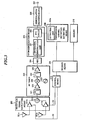
- FIG. 3 is a block diagram showing the general configuration of a receiver according to the first embodiment.
- the transmission signal under the OFDM transmission scheme is received by a plurality of antennas 301a and 301b.
- the number of antennas is at least two.
- Reception signal outputting means 302 selects the transmission signal received by the antenna 301a or 301b which is selected based on select signals S1 and S2 of decision mean 309, and outputs the same to an RF tuner 303.
- This reception signal outputting means 302 comprises AGC amplifiers 311a and 311b, and an adding unit 312.
- the gain of the AGC amplifier 311a or 311b which is provided for the antenna 301a or 301b unselected by the select signals S1 and S2 is lowered to interrupt the input, or to decrease the proportion in the combining ratio of the transmission signals in the adding unit 312.
- the reception signal output means 302 is not limited to the configuration of combining the transmission signals thus by using the phase difference feeding method, but may be of antenna switching method in which the AGC amplifiers 311a and 311b are switched to select either one of the antennas 301a and 301b.
- the following description will deal with the configuration of the antenna switching method in which the antennas 301a and 301b are switched selectively based on the select signals S1 and S2.
- the RF tuner 303 includes filters 321 and 322, variable gain amplifiers 323 and 324, an oscillator 325, and a mixer 326. This RF tuner 303 tunes to the OFDM signal of the desired wave out of the transmission signals selected by the reception signal output means 302, converts it into an OFDM signal of intermediate frequency by using the mixer 326, and outputs the resultant to an ADC 304.
- the ADC 304 applies analog-to-digital conversion to the transmission signal of intermediate frequency output from the RF tuner 303, and outputs the resultant to OFDM demodulation means 305.
- the OFDM demodulation means 305 comprises an orthogonal demodulation unit 331 and an FFT circuit 332.
- the orthogonal demodulation unit 331 converts the digitalized transmission signal into a baseband signal (complex baseband OFDM signal).
- the FFT circuit 322 receives the baseband signal, extracts signals included in a predetermined FFT window period, and performs FFT (Fast Fourier Transform) to convert the signals into ones on the frequency axis.
- demodulated-wave symbol signals can be obtained from a plurality of respective orthogonal frequency signals constituting the OFDM signal.
- Demodulation/decoding means 306 demodulates these modulated-wave symbol signals into symbol data, and then decodes the data for reproduction and outputs the resultant through an output terminal 307.
- Transmission channel distortion estimating means 308 has an extracting unit 308a for extracting pilot signals.
- the extracting unit 308a extracts pilot signals SP from the signal (carrier) demodulated by the OFDM demodulation means 305.
- the transmission channel distortion estimating means 308 estimates the distortion of the transmission channel from the extracted pilot signals.
- the pilot signals exhibit the frequency characteristic as shown in Fig. 4.
- Fig. 4 is a diagram showing the frequency characteristic of the pilot signals received at the receiving side.
- the y- and x-axes of Fig. 4 are the same as those of Fig. 2, and description thereof will be omitted.
- the frequency-specific powers of the pilot signals SP become uneven as shown in Fig. 4, causing such phenomena that pilot signals SP at some frequencies drop in power.
- the decision means 309 compares the pilot signals SP extracted by the transmission channel distortion estimating means 308 and a reference value for comparison stored in a memory 310, and outputs the result of comparison to control means 313.
- the control means 313 exercises control for changing the receiving condition based on the result of comparison. Specifically, the control means 313 operates the reception signal outputting means 302 to switch to either one of the antennas 301a and 301b selectively. This makes it possible to conduct reception by using the antenna 301a or 301b which is in an optimum state of reception.
- the memory 310 contains various information concerning the receiver, such as the reference value for comparison and the information on the extracted pilot signals (amplitudes and phases) .
- the memory 310 contains a reference value for an SP carrier power difference of the pilot signals SP to be compared with.
- This SP carrier power difference is the differential power H - L between the pilot signals H of higher power and the pilot signals L of lower power among the pilot signals SP of the respective frequencies shown in Fig. 4.
- the group of pilot signals H of higher power include SP1-SP3 and SP7-SPn.
- the group of pilot signals L of lower power include SP4-SP6.
- the decision means 309 compares the differences between the frequency-specific powers of the pilot signals extracted by the transmission channel distortion estimating means 308 and the reference value stored in the memory 310. If the differences between the frequency-specific powers of the pilot signals exceed the reference value, or threshold, the resulting decision to switch the antennas 301a and 301b selectively is output to the control means 313. The control means 313 then operates to change the receiving condition. Specifically, given that the power difference, or reference value, set in the memory 310 is 20 dB, the decision means 309 outputs the resulting decision to start the operation of changing the receiving condition to the control means 313 when the differential power H - L is greater than or equal to the threshold value, or the power difference of 20 dB.
- Fig. 5 is a flowchart for explaining the operation of changing the receiving condition according to the example 1.
- the individual components shown in Fig. 3 perform signal processing on this transmission signal.
- a signal is thus demodulated by the FFT circuit 332 of the OFDM demodulation means 305.
- the extracting unit 308a extracts pilot signals SP from the signal demodulated by the OFDM demodulation means 305 (step S501).
- the transmission channel distortion estimating means 308 calculates the SP carrier power difference H - L of the pilot signals described with reference to Fig. 4, based on the pilot signals extracted by the extracting unit 308a (step S502) .
- the SP carrier power difference H-L is the differential power between the pilot signals H of higher power and the pilot signals L of lower power among the pilot signals SP of respective frequencies.
- the power of a pilot signal H having the highest power and that of a pilot signal L having the lowest power may be compared across the frequencies.
- the power average of a plurality of pilot signals H in a predetermined range of highest powers and that of a plurality of pilot signals L in a predetermined range of lowest powers may be compared across the frequencies.
- moving averages are obtained for a plurality of pilot signals SP of adjoining frequencies, and the SP carrier power difference H - L is calculated from the moving averages.
- Fig. 6 is a diagram showing the characteristic of moving averages, taken across frequencies, of the pilot signals received at the receiving side.
- the y- and x-axes of Fig. 6 are the same as those of Fig. 2, and description thereof will be omitted.
- the frequency-specificpowers of the pilot signals SP become uneven, causing such phenomena that pilot signals SP at some frequencies drop in power as shown in Fig. 4 seen above. Taking the moving averages of the powers taken across frequencies in the state of Fig. 4 results in the state of Fig. 6.
- the decision means 309 compares the SP carrier power difference H - L determined as described above and the reference value (step S503) . If the result of comparison shows that the SP carrier power difference H - L is greater than the reference value (step S503: Yes) , it is determined that the operation of changing the receiving condition is required since the SP carrier power difference H - L shows a large difference in power. The changing of the receiving condition is thus started (step S504 ) . Consequently, the control means 313 outputs the select signals S1 and S2 for switching the antenna selected so far to the other antenna (see Fig. 3). The reception signal outputting means 302, if it has selected the antenna 301 so far, selects the other antenna 301b.
- step S503 if the SP carrier power difference H - L is smaller than the reference value (step S503: No), it is determined that the operation of changing the receiving condition is unnecessary since the SP carrier power difference H - L shows a small difference in power.
- the receiving condition is thus kept as is (unchanged) , and the operation is ended (step S505).
- the operation of changing the receiving condition shown in the foregoing steps S501 to 505 is performed at timing in minimum units of a single symbol, or a plurality of symbols.
- This timing of the operation of changing the receiving condition may be set depending on the receiving situation. For example, based on the modulation methods of the receiver and other information, the number of symbols for use in calculating the SP carrier power difference at step S502 may be changed dynamically (with a lapse of time) so that the operation of changing the receiving condition is performed in units of the number of symbols after this dynamic change.
- the description that the receiving condition is kept as is at step S505 means that the antenna switching processing is not performed and the antenna selected so far is kept selected.
- the operation of changing the receiving condition can be effected by brief processing of simple comparison alone, using the SP carrier power difference of the transmission signals for comparison. This allows the stabilization of the state of reception.
- the transmission channel distortion estimating means 308 estimates the distortion of the transmission channel based on phase differences between a plurality of pilot signals. More specifically, the transmission channel distortion estimating means 308 calculates phase differences from a plurality of pilot signals extracted by the extracting unit 308a, and the decision unit 309 compares the phase differences and a reference value previously stored in the memory 310 to determine whether or not to perform the operation of changing the receiving condition. For example, if adjoining pilot signals have a phase difference greater than or equal to the reference value, the operation of changing the receiving condition is performed. As with the power differences, the phase differences can thus be used as the condition for performing the operation of changing the receiving condition.
- FIG. 7 is a flowchart for explaining the operation of changing the receiving condition according to the example 2.
- the parameter n represents the number of symbols of the pilot signals SP to be used for deciding on the operation of changing the receiving condition.
- the parameter m represents the number of symbols of the pilot signals SP stored in the memory 310. This m has an initial value of zero.
- the individual components shown in Fig. 3 perform signal processing on this transmission signal.
- a signal is thus demodulated by the FFT circuit 332 of the OFDM demodulation means 305.
- the extracting unit 308a extracts a pilot signal SP from the signal demodulated by the OFDM demodulationmeans 305 (step S701) .
- the extractedpilot signal SP is stored into the memory 310 (step S702). By this storage, the value of m is incremented by one (step S703).
- the transmission channel distortion estimating means 308 derives the SP carrier power difference H - L of the pilot signals SP, described with reference to Fig. 4 (step S706).
- the SP carrier power difference H - L can be calculated by using various specific techniques.
- the decision means 309 compares the SP carrier power difference H - L determined as described above and the reference value (step S707). If the result of comparison shows that the SP carrier power difference H - L is greater than the reference value (step S707: Yes), it is determined that the operation of changing the receiving condition is required since the SP carrier power difference H - L itself shows a large difference in power. The operation of changing the receiving condition is thus started (step S708), and the single round of processing is ended. Consequently, the decision means 309 outputs the select signals S1 and S2 for switching the antenna selected so far to the other antenna (see Fig. 3) . Specifically, if the antenna 301 has been selected so far, the other antenna 301b is selected.
- step S707 if the SP carrier power difference H - L is smaller than the reference value (step S707: No), it is determined that the operation of changing the receiving condition is unnecessary since the SP carrier power difference H - L shows a small difference in power.
- the receiving condition is thus kept as is (unchanged) (step S709), and the single round of processing is ended.
- the operation of changing the receiving condition can be started and ended at timing in units of a single symbol or a plurality of symbols after the transmission signals as many as the number n of symbols in use are received.
- SP carrier power differences H - L for a plurality of symbols may be calculated and stored into the memory.
- the SP carrier power differences H- L for the plurality of symbols stored in the memory are averaged and used for comparison.
- whether or not to change the receiving condition is controlled by using the plurality of symbols of pilot signals SP. It is therefore possible to perform the antenna switching with stability even when the SP carrier power difference varies symbol by symbol.
- the power of the transmission signal may be detected based on any of the RF signal from the RF tuner 303, the IF signal past the mixer 326, and the baseband signal past the filter 322. In another possible configuration, the detection may be based on the digital signal past the ADC 304.
- the frequency-specific SP carrier power differences can be used to determine whether or not to perform the operation of changing the receiving condition. This can provide the effect of stabilizing the state of reception.
- the first embodiment is configured to use the SP carrier power differences for comparison
- the second embodiment is configured to use SP impulse responses of the pilot signals SP for comparison.
- Fig. 8 is a block diagram showing the general configuration of a receiver according to the second embodiment.
- the same components as those of Fig. 3 described in the first embodiment will be designated by identical numerals, and description thereof will be omitted.
- the configuration of Fig. 8 differs from that of Fig. 3 in that the transmission channel distortion estimating means 308 is provided with an SP impulse response difference calculating unit 801.
- the SP impulse response difference calculating unit 801 is formed by subjecting the pilot signal SP obtained by the FFT circuit 332 of the OFDM demodulation means 305 to additional FFT (Fast Fourier Transform) .
- Fig. 9 is a diagram showing an example of the SP impulse response characteristic of a received transmission signal.
- the y-axis represents the power
- the x-axis the time.
- the characteristics of the pilot signals at the frequencies shown in Fig. 4 seen above are represented by respective crosses. Given an ideal distortion-free transmission channel, the powers of the SP impulse responses would concentrate at time 0, with no delay or lead in time.
- the pilot signals SP exhibit the characteristic that they are also distributed over the leading side and trailing side of the time axis, aside from the pilot signal SPR falling on the area of time 0.
- the pilot signal SPM shown in Fig. 9 appears due to multipath distortion of T in delay time. If the multipath wave SPM has high power with respect to the desired wave of the pilot signal SP, or SPR, it interferes with the desired wave to contribute a degraded state of reception. For this reason, the operation of changing the receiving condition shall be performed when the difference H - L between the power H of the desired wave of the pilot signal SP, or SPR, and the power L of the multipath or other interference wave SPM falls to or below a certain value.
- the memory 310 shown in Fig. 8 contains a reference value (threshold) for an SP impulse response difference of the pilot signals SP to be comparedwith.
- the decisionmeans 309 shown in Fig. 8 compares the SP impulse response difference of the pilot signals calculated by the SP impulse response difference calculating unit 801 and the reference value stored in the memory 310. Then, the operation of changing the receiving condition through selective switching of the antennas 301a and 301b is performed when the SP impulse response difference between a plurality of pilot signals is smaller than the reference value.
- Fig. 10 is a flowchart for explaining the operation of changing the receiving condition according to the example 3.
- the individual components shown in Fig. 8 perform signal processing on this transmission signal.
- a signal is thus demodulated by the FFT circuit 332 of the OFDM demodulation means 305.
- the extracting unit 308a extracts pilot signals SP from the signal demodulated by the OFDM demodulation means 305 (step S1001).
- the SP impulse response difference calculating unit 801 calculates the SP impulse responses of a plurality of pilot signals extracted by the extracting unit 308a. Then, as shown in Fig. 9, the SP impulse response difference calculating unit 801 calculates the difference H - L between the power H of the desired wave SPR at time 0 and the power L of the multipath or other interference wave SPM having the second highest power (step S1002).
- the decision means 309 compares the SP impulse response difference H - L determined as described above and the reference value (step S1003). If the result of comparison shows that the calculated SP impulse response difference H - L is smaller than the SP impulse response difference shown by the reference value (step S1003: Yes), it is determined that the SP impulse response of the interference wave SPM is high in power, requiring the operation of changing the receiving condition. The operation of changing the receiving condition is thus started (step S1004). Consequently, the decision means 309 outputs the select signals S1 and S2 for switching the antenna selected so far to the other antenna (see Fig. 8). Specifically, if the antenna 301 has been selected so far, the other antenna 301b is selected.
- step S1003 if the calculated SP impulse response difference H - L is greater than the SP impulse response difference shown by the reference value (step S1003: No), it is determined that the SP impulse response of the interference wave SPM is low in power, not requiring the operation of changing the receiving condition. The processing is thus ended with the receiving condition unchanged (step S1005).
- Each of the processes of the foregoing steps S1001 to S1005 is performed in minimum units of a single symbol, or a plurality of symbols.
- the operation of changing the receiving condition can be effected by brief processing of simply comparing the SP impulse response difference of the transmission signals by using the reference value. This allows the stabilization of the state of reception.
- the frequency-specific SP impulse response differences can be used to determine whether or not to perform the operation of changing the receiving condition. This can provide the effect of stabilizing the state of reception.
- the foregoing embodiments have dealt with the method of estimating distortion of the transmission channel based on a power difference or phase difference of pilot signals SP or an impulse response difference of pilot signals.
- the method of estimating distortion of the transmission channel is not limited thereto, however.
- FFT may be performed in units of a single symbol.
- the powers of the respective carriers are determined to derive the frequency characteristic, and the distortion of the transmission channel is estimated based on the frequency characteristic.
- the distortion of the transmission channel can be estimated by deriving the frequency characteristic of the transmission channel from information on transmission signals other than pilot signals SP.
- the embodiments have dealt with the configuration of receiving transmission signals of OFDM transmission scheme.
- the transmission signals to be received are not limited thereto, however.
- the operation of changing the receiving condition can be performed with stability in response to degradations in the frequency-specific powers of the received transmission signal or the occurrence of multipath and other interference waves, as in the foregoing embodiments.
- single-tuner diversity receivers have been described as the concrete examples. Nevertheless, the present invention is also applicable to two-tuner diversity receivers which have two tuners and combine the outputs of the plurality of tuners, and receivers which have more tuners.
- the receivers described in the embodiments can be controlled through the execution of a reception controlling program prepared in advance on a computer such as a personal computer.
- This program is recorded on a computer-readable recording medium such as a hard disk, flexible disk, CD-ROM, MO, and DVD, and is read by the computer from the recording medium for execution.
- This program may also be on a transmission medium capable of distribution over a network such as the Internet.
- the receiver, the receiving method, the reception controlling program, and the recording medium according to the embodiments are applicable to the field of application of broadcasting and communication, and can be applied to radios, television sets, and navigation systems implementing the same, as well as wide-band radio and the like.
- Stable reception quality can be provided with such applications as vehicle-mounted (such as car, train, and ship) or portable receivers in particular.
Landscapes
- Engineering & Computer Science (AREA)
- Computer Networks & Wireless Communication (AREA)
- Signal Processing (AREA)
- Radio Transmission System (AREA)
Claims (9)
- Empfänger, der folgendes aufweist:- eine Vielzahl von Antennen (301a, 301b) zum Empfangen eines Sendesignals;- eine Empfangssignal-Abgabeeinrichtung (302) zum Abgeben eines Empfangssignals unter Verwendung von einer oder mehreren Antennen aus der Vielzahl der Antennen (301a, 301b);- eine Übertragungskanalverzerrungs-Schätzeinrichtung (308) zum Abschätzen der Verzerrung eines Übertragungskanals auf der Basis des von der Empfangssignal-Abgabeeinrichtung (302) abgegebenen Empfangssignals;- eine Entscheidungseinrichtung (309) zum Entscheiden, ob eine Empfangsbedingung der Empfangssignal-Abgabeeinrichtung (302) zu ändern ist oder nicht, und zwar auf der Basis der Verzerrung des Übertragungskanals, wie diese von der Übertragungskanalverzerrungs-Schätzeinrichtung (308) abgeschätzt worden ist; und- eine Steuereinrichtung (313) zum Steuern der Empfangsbedingung der Empfangssignal-Abgabeeinrichtung (302), wenn die Entscheidungseinrichtung (309) auf der Basis der Verzerrung des Empfangskanals die Entscheidung trifft, die Empfangsbedingung der Empfangssignal-Abgabeeinrichtung zu ändern,dadurch gekennzeichnet,
daß die Übertragungskanalverzerrungs-Schätzeinrichtung (308) die Leistungseigenschaften von Teilen des Signals nach seiner Demodulation in einer Demodulationseinrichtung (305) mißt und dies zum Abschätzen der Verzerrung in dem Übertragungskanal verwendet. - Empfänger nach Anspruch 1,
weiterhin gekennzeichnet durch eine Extrahiereinrichtung (308a) zum Extrahieren einer Vielzahl von Pilotsignalen (SP), die in dem von der Empfangssignal-Abgabeeinrichtung (302) abgegebenen Empfangssignal enthalten sind, wobei die Übertragungskanalverzerrungs-Schätzeinrichtung (308) die Verzerrung des Übertragungskanals auf der Basis der Vielzahl von Pilotsignalen (SP) abschätzt, die durch die Extrahiereinrichtung (308a) extrahiert werden. - Empfänger nach Anspruch 2,
dadurch gekennzeichnet,
daß die Übertragungskanalverzerrungs-Schätzeinrichtung (308) die Verzerrung des Übertragungskanals auf der Basis einer Leistungsdifferenz zwischen der Vielzahl der extrahierten Pilotsignale (SP) abschätzt. - Empfänger nach Anspruch 2,
dadurch gekennzeichnet,
daß die Übertragungskanalverzerrungs-Schätzeinrichtung (308) die Verzerrung des Übertragungskanals auf der Basis einer Phasendifferenz zwischen der Vielzahl der Pilotsignale (SP) abschätzt. - Empfänger nach Anspruch 2,
dadurch gekennzeichnet,
daß die Übertragungskanalverzerrungs-Schätzeinrichtung (308) die Verzerrung des Übertragungskanals auf der Basis einer Impulsansprechdifferenz zwischen der Vielzahl der Pilotsignale (SP) abschätzt. - Empfänger nach einem der Ansprüche 3 bis 5,
dadurch gekennzeichnet,
daß die Entscheidungseinrichtung (309) die Entscheidung, ob die Empfangsbedingung der Empfangssignal-Abgabeeinrichtung (302) zu ändern ist oder nicht, durch Vergleichen der Leistungsdifferenz, der Phasendifferenz oder der Impulsansprechdifferenz mit einem Referenzwert trifft. - Empfangsverfahren, das folgende Schritte aufweist:- einen Empfangssignal-Abgabeschritt zum Abgeben eines Empfangssignals unter Verwendung von einer oder mehreren Antennen aus einer Vielzahl von Antennen (301, 301b) für den Empfang eines Sendesignals;- eine Übertragungskanalverzerrungs-Abschätzschritt zum Abschätzen einer Verzerrung eines Übertragungskanals auf der Basis des in dem Empfangssignal-Abgabeschritt abgegebenen Empfangssignals;- einen Entscheidungsschritt zum Entscheiden, ob eine Empfangsbedingung des Empfangssignal-Abgabeschrittes zu ändern ist oder nicht, auf der Basis der in dem Übertragungskanalverzerrungs-Abschätzschritt abgeschätzten Verzerrung des Übertragungskanals; und- einen Steuerschritt zum Steuern der Empfangsbedingung des Empfangssignal-Abgabeschrittes, wenn in dem Entscheidungsschritt die Entscheidung getroffen worden ist, die Empfangsbedingung des Empfangssignal-Abgabeschrittes auf der Basis der Verzerrung des Übertragungskanals zu ändern,dadurch gekennzeichnet,
daß in dem Übertragungskanalverzerrungs-Abschätzschritt die Leistungseigenschaften von Teilen des Signals nach seiner Demodulation in einer Demodulationseinrichtung gemessen werden und dies zum Abschätzen der Verzerrung in dem Übertragungskanal verwendet wird. - Empfangs-Steuerprogramm zum Steuern eines Empfängers unter Verwendung eines Computers, wobei der Empfänger ein Empfangssignal unter Verwendung von einer oder mehreren Antennen aus einer Vielzahl von Antennen (301a, 301b) für den Empfang eines Sendesignals abgibt, wobei das Empfangs-Steuerprogramm den Computer veranlaßt, die Verzerrung eines Übertragungskanals auf der Basis des Empfangssignals abzuschätzen sowie das Empfangssignal auf der Basis der geschätzten Verzerrung des Übertragungskanals zu steuern,
dadurch gekennzeichnet,
daß der Übertragungskanalverzerrungs-Abschätzschritt die Leistungseigenschaften von Teilen des Signals nach seiner Demodulation mißt und dies zum Abschätzen der Verzerrung in dem Übertragungskanal verwendet. - Computerlesbares Speichermedium,
in dem ein Empfangs-Steuerprogramm gemäß Anspruch 8 gespeichert ist.
Applications Claiming Priority (2)
| Application Number | Priority Date | Filing Date | Title |
|---|---|---|---|
| JP2003414834A JP2005176048A (ja) | 2003-12-12 | 2003-12-12 | 受信機、受信方法、受信制御用プログラム及び記録媒体 |
| JP2003414834 | 2003-12-12 |
Publications (2)
| Publication Number | Publication Date |
|---|---|
| EP1542420A1 EP1542420A1 (de) | 2005-06-15 |
| EP1542420B1 true EP1542420B1 (de) | 2007-07-11 |
Family
ID=34510563
Family Applications (1)
| Application Number | Title | Priority Date | Filing Date |
|---|---|---|---|
| EP04029192A Expired - Lifetime EP1542420B1 (de) | 2003-12-12 | 2004-12-09 | Verfahren und Vorrichtung mit adaptiven Gruppenantennenempfang |
Country Status (4)
| Country | Link |
|---|---|
| US (1) | US20050129155A1 (de) |
| EP (1) | EP1542420B1 (de) |
| JP (1) | JP2005176048A (de) |
| DE (1) | DE602004007461D1 (de) |
Families Citing this family (44)
| Publication number | Priority date | Publication date | Assignee | Title |
|---|---|---|---|---|
| CN100591059C (zh) * | 2003-10-03 | 2010-02-17 | 诺基亚公司 | 接收多载波传输的方法、系统和接收机 |
| JP2006287845A (ja) * | 2005-04-05 | 2006-10-19 | Fujitsu Ten Ltd | ダイバーシティ受信機及び信号処理回路 |
| KR100668663B1 (ko) * | 2005-09-30 | 2007-01-12 | 한국전자통신연구원 | Ofdm 시스템에서 이동국의 자동이득제어 장치 및 방법 |
| JP4802763B2 (ja) * | 2006-02-28 | 2011-10-26 | カシオ計算機株式会社 | Ofdm信号受信装置、ofdm信号受信方法及び地上波デジタル放送受信装置 |
| JP2007258819A (ja) * | 2006-03-20 | 2007-10-04 | Casio Comput Co Ltd | Ofdm受信装置、ofdm受信方法及び地上波デジタル受信装置 |
| JP4692761B2 (ja) * | 2006-03-29 | 2011-06-01 | カシオ計算機株式会社 | Ofdm受信装置、ofdm受信方法及び地上波デジタル受信装置 |
| EP1863191B1 (de) * | 2006-06-02 | 2012-03-14 | STMicroelectronics N.V. | Verfahren zur Verwaltung von eventuellen Interferenzen mit Antennenschaltung und Vorrichtung dafür |
| US8644413B2 (en) | 2012-05-29 | 2014-02-04 | Magnolia Broadband Inc. | Implementing blind tuning in hybrid MIMO RF beamforming systems |
| US8971452B2 (en) | 2012-05-29 | 2015-03-03 | Magnolia Broadband Inc. | Using 3G/4G baseband signals for tuning beamformers in hybrid MIMO RDN systems |
| US8837650B2 (en) | 2012-05-29 | 2014-09-16 | Magnolia Broadband Inc. | System and method for discrete gain control in hybrid MIMO RF beamforming for multi layer MIMO base station |
| US8767862B2 (en) | 2012-05-29 | 2014-07-01 | Magnolia Broadband Inc. | Beamformer phase optimization for a multi-layer MIMO system augmented by radio distribution network |
| US8861635B2 (en) | 2012-05-29 | 2014-10-14 | Magnolia Broadband Inc. | Setting radio frequency (RF) beamformer antenna weights per data-stream in a multiple-input-multiple-output (MIMO) system |
| US8599955B1 (en) | 2012-05-29 | 2013-12-03 | Magnolia Broadband Inc. | System and method for distinguishing between antennas in hybrid MIMO RDN systems |
| US8885757B2 (en) | 2012-05-29 | 2014-11-11 | Magnolia Broadband Inc. | Calibration of MIMO systems with radio distribution networks |
| US8811522B2 (en) | 2012-05-29 | 2014-08-19 | Magnolia Broadband Inc. | Mitigating interferences for a multi-layer MIMO system augmented by radio distribution network |
| US8649458B2 (en) | 2012-05-29 | 2014-02-11 | Magnolia Broadband Inc. | Using antenna pooling to enhance a MIMO receiver augmented by RF beamforming |
| US8654883B2 (en) | 2012-05-29 | 2014-02-18 | Magnolia Broadband Inc. | Systems and methods for enhanced RF MIMO system performance |
| US8842765B2 (en) | 2012-05-29 | 2014-09-23 | Magnolia Broadband Inc. | Beamformer configurable for connecting a variable number of antennas and radio circuits |
| US8619927B2 (en) * | 2012-05-29 | 2013-12-31 | Magnolia Broadband Inc. | System and method for discrete gain control in hybrid MIMO/RF beamforming |
| US9154204B2 (en) | 2012-06-11 | 2015-10-06 | Magnolia Broadband Inc. | Implementing transmit RDN architectures in uplink MIMO systems |
| US9343808B2 (en) | 2013-02-08 | 2016-05-17 | Magnotod Llc | Multi-beam MIMO time division duplex base station using subset of radios |
| US8797969B1 (en) | 2013-02-08 | 2014-08-05 | Magnolia Broadband Inc. | Implementing multi user multiple input multiple output (MU MIMO) base station using single-user (SU) MIMO co-located base stations |
| US8989103B2 (en) | 2013-02-13 | 2015-03-24 | Magnolia Broadband Inc. | Method and system for selective attenuation of preamble reception in co-located WI FI access points |
| US8774150B1 (en) | 2013-02-13 | 2014-07-08 | Magnolia Broadband Inc. | System and method for reducing side-lobe contamination effects in Wi-Fi access points |
| US20140226740A1 (en) | 2013-02-13 | 2014-08-14 | Magnolia Broadband Inc. | Multi-beam co-channel wi-fi access point |
| US9155110B2 (en) | 2013-03-27 | 2015-10-06 | Magnolia Broadband Inc. | System and method for co-located and co-channel Wi-Fi access points |
| US9100968B2 (en) | 2013-05-09 | 2015-08-04 | Magnolia Broadband Inc. | Method and system for digital cancellation scheme with multi-beam |
| US9425882B2 (en) | 2013-06-28 | 2016-08-23 | Magnolia Broadband Inc. | Wi-Fi radio distribution network stations and method of operating Wi-Fi RDN stations |
| US8995416B2 (en) | 2013-07-10 | 2015-03-31 | Magnolia Broadband Inc. | System and method for simultaneous co-channel access of neighboring access points |
| US8824596B1 (en) | 2013-07-31 | 2014-09-02 | Magnolia Broadband Inc. | System and method for uplink transmissions in time division MIMO RDN architecture |
| US9497781B2 (en) | 2013-08-13 | 2016-11-15 | Magnolia Broadband Inc. | System and method for co-located and co-channel Wi-Fi access points |
| US9060362B2 (en) | 2013-09-12 | 2015-06-16 | Magnolia Broadband Inc. | Method and system for accessing an occupied Wi-Fi channel by a client using a nulling scheme |
| US9088898B2 (en) | 2013-09-12 | 2015-07-21 | Magnolia Broadband Inc. | System and method for cooperative scheduling for co-located access points |
| US9172454B2 (en) | 2013-11-01 | 2015-10-27 | Magnolia Broadband Inc. | Method and system for calibrating a transceiver array |
| US8891598B1 (en) | 2013-11-19 | 2014-11-18 | Magnolia Broadband Inc. | Transmitter and receiver calibration for obtaining the channel reciprocity for time division duplex MIMO systems |
| US8929322B1 (en) | 2013-11-20 | 2015-01-06 | Magnolia Broadband Inc. | System and method for side lobe suppression using controlled signal cancellation |
| US8942134B1 (en) | 2013-11-20 | 2015-01-27 | Magnolia Broadband Inc. | System and method for selective registration in a multi-beam system |
| US9294177B2 (en) | 2013-11-26 | 2016-03-22 | Magnolia Broadband Inc. | System and method for transmit and receive antenna patterns calibration for time division duplex (TDD) systems |
| US9014066B1 (en) | 2013-11-26 | 2015-04-21 | Magnolia Broadband Inc. | System and method for transmit and receive antenna patterns calibration for time division duplex (TDD) systems |
| US9042276B1 (en) | 2013-12-05 | 2015-05-26 | Magnolia Broadband Inc. | Multiple co-located multi-user-MIMO access points |
| US9100154B1 (en) | 2014-03-19 | 2015-08-04 | Magnolia Broadband Inc. | Method and system for explicit AP-to-AP sounding in an 802.11 network |
| US9172446B2 (en) | 2014-03-19 | 2015-10-27 | Magnolia Broadband Inc. | Method and system for supporting sparse explicit sounding by implicit data |
| US9271176B2 (en) | 2014-03-28 | 2016-02-23 | Magnolia Broadband Inc. | System and method for backhaul based sounding feedback |
| JP6672846B2 (ja) * | 2016-02-03 | 2020-03-25 | 富士通株式会社 | 無線装置、及び、位相制御方法 |
Family Cites Families (5)
| Publication number | Priority date | Publication date | Assignee | Title |
|---|---|---|---|---|
| US4499606A (en) * | 1982-12-27 | 1985-02-12 | Sri International | Reception enhancement in mobile FM broadcast receivers and the like |
| JPH0746168A (ja) * | 1993-07-27 | 1995-02-14 | Matsushita Electric Ind Co Ltd | ダイバーシティ受信機 |
| US6141393A (en) * | 1999-03-03 | 2000-10-31 | Motorola, Inc. | Method and device for channel estimation, equalization, and interference suppression |
| JP3782330B2 (ja) * | 2001-09-14 | 2006-06-07 | 富士通株式会社 | Ofdm受信方法及びofdm受信装置 |
| US6922549B2 (en) * | 2003-10-31 | 2005-07-26 | Cisco Technology, Inc. | Error vector magnitude selection diversity metric for OFDM |
-
2003
- 2003-12-12 JP JP2003414834A patent/JP2005176048A/ja not_active Abandoned
-
2004
- 2004-12-09 EP EP04029192A patent/EP1542420B1/de not_active Expired - Lifetime
- 2004-12-09 DE DE602004007461T patent/DE602004007461D1/de not_active Expired - Lifetime
- 2004-12-09 US US11/007,195 patent/US20050129155A1/en not_active Abandoned
Also Published As
| Publication number | Publication date |
|---|---|
| US20050129155A1 (en) | 2005-06-16 |
| EP1542420A1 (de) | 2005-06-15 |
| JP2005176048A (ja) | 2005-06-30 |
| DE602004007461D1 (de) | 2007-08-23 |
Similar Documents
| Publication | Publication Date | Title |
|---|---|---|
| EP1542420B1 (de) | Verfahren und Vorrichtung mit adaptiven Gruppenantennenempfang | |
| JP3389178B2 (ja) | Ofdmダイバーシチ受信装置 | |
| EP1041736B1 (de) | Diversitätsempfänger für OFDM-Burst-Signalübertragung | |
| US7636593B2 (en) | Receiver | |
| US20050113048A1 (en) | Receiver, receiving method, reception controlling program, and recording medium | |
| JP3642784B2 (ja) | ダイバーシチ受信装置およびダイバーシチ受信方法 | |
| US5973642A (en) | Adaptive antenna arrays for orthogonal frequency division multiplexing systems with co-channel interference | |
| US9608700B2 (en) | Wireless transmitting and receiving device and method | |
| US6668172B1 (en) | Reception apparatus and reception processing method | |
| EP1798871A1 (de) | Zweifach-Tuner-Mehrfachempfang für Hintergrundverarbeitung und Reduzierung von Mehrwegestörungen | |
| US20040229581A1 (en) | Diversity receiver and diversity receiving method | |
| US6836507B1 (en) | Symbol synchronizer for software defined communications system signal combiner | |
| US20020050948A1 (en) | Adaptive receiver having adaptive array unit and equalizer unit | |
| JP2004135120A (ja) | ダイバーシティ受信装置及びダイバーシティ受信方法 | |
| JP4574681B2 (ja) | ダイバーシチ受信装置 | |
| KR20090037328A (ko) | Ofdm 수신 장치 | |
| JP2004336279A (ja) | Ofdm受信装置および受信方法 | |
| JP2002152170A (ja) | ダイバーシティ受信機及び直交周波数分割多重信号受信方法 | |
| JP4095602B2 (ja) | 受信装置 | |
| JP2006217399A (ja) | 受信装置 | |
| JP4378263B2 (ja) | 受信装置 | |
| JP4011384B2 (ja) | ダイバーシティ受信機 | |
| JP2005269181A (ja) | 車載デジタル通信受信装置 | |
| EP1549009A1 (de) | Schätzung eines Übertragungspfades in einem Diversitätsempfänger mittels Pilotsignale | |
| JP3606450B2 (ja) | ダイバーシティ受信機及び直交周波数分割多重信号受信方法 |
Legal Events
| Date | Code | Title | Description |
|---|---|---|---|
| PUAI | Public reference made under article 153(3) epc to a published international application that has entered the european phase |
Free format text: ORIGINAL CODE: 0009012 |
|
| AK | Designated contracting states |
Kind code of ref document: A1 Designated state(s): AT BE BG CH CY CZ DE DK EE ES FI FR GB GR HU IE IS IT LI LT LU MC NL PL PT RO SE SI SK TR |
|
| AX | Request for extension of the european patent |
Extension state: AL BA HR LV MK YU |
|
| 17P | Request for examination filed |
Effective date: 20050628 |
|
| AKX | Designation fees paid |
Designated state(s): DE FR GB |
|
| GRAP | Despatch of communication of intention to grant a patent |
Free format text: ORIGINAL CODE: EPIDOSNIGR1 |
|
| GRAS | Grant fee paid |
Free format text: ORIGINAL CODE: EPIDOSNIGR3 |
|
| GRAA | (expected) grant |
Free format text: ORIGINAL CODE: 0009210 |
|
| AK | Designated contracting states |
Kind code of ref document: B1 Designated state(s): DE FR GB |
|
| REG | Reference to a national code |
Ref country code: GB Ref legal event code: FG4D |
|
| REF | Corresponds to: |
Ref document number: 602004007461 Country of ref document: DE Date of ref document: 20070823 Kind code of ref document: P |
|
| ET | Fr: translation filed | ||
| PLBE | No opposition filed within time limit |
Free format text: ORIGINAL CODE: 0009261 |
|
| STAA | Information on the status of an ep patent application or granted ep patent |
Free format text: STATUS: NO OPPOSITION FILED WITHIN TIME LIMIT |
|
| 26N | No opposition filed |
Effective date: 20080414 |
|
| PG25 | Lapsed in a contracting state [announced via postgrant information from national office to epo] |
Ref country code: DE Free format text: LAPSE BECAUSE OF FAILURE TO SUBMIT A TRANSLATION OF THE DESCRIPTION OR TO PAY THE FEE WITHIN THE PRESCRIBED TIME-LIMIT Effective date: 20071012 |
|
| REG | Reference to a national code |
Ref country code: FR Ref legal event code: ST Effective date: 20081020 |
|
| PG25 | Lapsed in a contracting state [announced via postgrant information from national office to epo] |
Ref country code: FR Free format text: LAPSE BECAUSE OF NON-PAYMENT OF DUE FEES Effective date: 20071231 |
|
| GBPC | Gb: european patent ceased through non-payment of renewal fee |
Effective date: 20081209 |
|
| PG25 | Lapsed in a contracting state [announced via postgrant information from national office to epo] |
Ref country code: GB Free format text: LAPSE BECAUSE OF NON-PAYMENT OF DUE FEES Effective date: 20081209 |