EP1543964A2 - Unité d'impression pour une machine à imprimer - Google Patents
Unité d'impression pour une machine à imprimer Download PDFInfo
- Publication number
- EP1543964A2 EP1543964A2 EP05101366A EP05101366A EP1543964A2 EP 1543964 A2 EP1543964 A2 EP 1543964A2 EP 05101366 A EP05101366 A EP 05101366A EP 05101366 A EP05101366 A EP 05101366A EP 1543964 A2 EP1543964 A2 EP 1543964A2
- Authority
- EP
- European Patent Office
- Prior art keywords
- printing unit
- cylinder
- unit according
- linear
- side frame
- Prior art date
- Legal status (The legal status is an assumption and is not a legal conclusion. Google has not performed a legal analysis and makes no representation as to the accuracy of the status listed.)
- Granted
Links
- 238000007639 printing Methods 0.000 title claims abstract description 219
- 238000012546 transfer Methods 0.000 claims abstract description 138
- 230000033001 locomotion Effects 0.000 claims description 46
- 230000008878 coupling Effects 0.000 claims description 24
- 238000010168 coupling process Methods 0.000 claims description 24
- 238000005859 coupling reaction Methods 0.000 claims description 24
- 230000000295 complement effect Effects 0.000 claims description 2
- XAGFODPZIPBFFR-UHFFFAOYSA-N aluminium Chemical compound [Al] XAGFODPZIPBFFR-UHFFFAOYSA-N 0.000 abstract 1
- 229910052782 aluminium Inorganic materials 0.000 abstract 1
- 238000004519 manufacturing process Methods 0.000 description 23
- 230000000875 corresponding effect Effects 0.000 description 21
- 239000010410 layer Substances 0.000 description 16
- 239000002184 metal Substances 0.000 description 10
- WYWHKKSPHMUBEB-UHFFFAOYSA-N 6-Mercaptoguanine Natural products N1C(N)=NC(=S)C2=C1N=CN2 WYWHKKSPHMUBEB-UHFFFAOYSA-N 0.000 description 9
- 230000008859 change Effects 0.000 description 9
- 229940095374 tabloid Drugs 0.000 description 9
- 230000008901 benefit Effects 0.000 description 8
- 230000007246 mechanism Effects 0.000 description 8
- 230000005540 biological transmission Effects 0.000 description 7
- 238000010276 construction Methods 0.000 description 7
- 238000003860 storage Methods 0.000 description 7
- 230000001360 synchronised effect Effects 0.000 description 7
- 238000013461 design Methods 0.000 description 6
- 239000000314 lubricant Substances 0.000 description 6
- 238000005096 rolling process Methods 0.000 description 6
- 238000011161 development Methods 0.000 description 5
- 238000009826 distribution Methods 0.000 description 4
- 230000005284 excitation Effects 0.000 description 4
- 238000000034 method Methods 0.000 description 3
- 230000009467 reduction Effects 0.000 description 3
- 239000000758 substrate Substances 0.000 description 3
- 238000005406 washing Methods 0.000 description 3
- 238000007774 anilox coating Methods 0.000 description 2
- 230000015572 biosynthetic process Effects 0.000 description 2
- 230000001066 destructive effect Effects 0.000 description 2
- 238000005538 encapsulation Methods 0.000 description 2
- 238000005461 lubrication Methods 0.000 description 2
- 238000012423 maintenance Methods 0.000 description 2
- 230000008569 process Effects 0.000 description 2
- 230000035939 shock Effects 0.000 description 2
- 239000002356 single layer Substances 0.000 description 2
- 239000007787 solid Substances 0.000 description 2
- 208000034656 Contusions Diseases 0.000 description 1
- 241000446313 Lamella Species 0.000 description 1
- 229910000831 Steel Inorganic materials 0.000 description 1
- 206010052428 Wound Diseases 0.000 description 1
- 208000027418 Wounds and injury Diseases 0.000 description 1
- 238000005452 bending Methods 0.000 description 1
- 230000009286 beneficial effect Effects 0.000 description 1
- 230000033228 biological regulation Effects 0.000 description 1
- 208000034526 bruise Diseases 0.000 description 1
- 238000004140 cleaning Methods 0.000 description 1
- 239000011248 coating agent Substances 0.000 description 1
- 238000000576 coating method Methods 0.000 description 1
- 238000012937 correction Methods 0.000 description 1
- 230000002596 correlated effect Effects 0.000 description 1
- 238000005520 cutting process Methods 0.000 description 1
- 238000013016 damping Methods 0.000 description 1
- 238000010017 direct printing Methods 0.000 description 1
- 238000005553 drilling Methods 0.000 description 1
- 238000005516 engineering process Methods 0.000 description 1
- 239000004744 fabric Substances 0.000 description 1
- 230000002349 favourable effect Effects 0.000 description 1
- 230000005764 inhibitory process Effects 0.000 description 1
- 238000009434 installation Methods 0.000 description 1
- 230000001050 lubricating effect Effects 0.000 description 1
- 239000000463 material Substances 0.000 description 1
- 238000007645 offset printing Methods 0.000 description 1
- 239000010893 paper waste Substances 0.000 description 1
- 230000002040 relaxant effect Effects 0.000 description 1
- 230000003068 static effect Effects 0.000 description 1
- 239000010959 steel Substances 0.000 description 1
Images





Classifications
-
- B—PERFORMING OPERATIONS; TRANSPORTING
- B41—PRINTING; LINING MACHINES; TYPEWRITERS; STAMPS
- B41F—PRINTING MACHINES OR PRESSES
- B41F13/00—Common details of rotary presses or machines
- B41F13/08—Cylinders
- B41F13/10—Forme cylinders
-
- B—PERFORMING OPERATIONS; TRANSPORTING
- B41—PRINTING; LINING MACHINES; TYPEWRITERS; STAMPS
- B41F—PRINTING MACHINES OR PRESSES
- B41F13/00—Common details of rotary presses or machines
- B41F13/08—Cylinders
-
- B—PERFORMING OPERATIONS; TRANSPORTING
- B41—PRINTING; LINING MACHINES; TYPEWRITERS; STAMPS
- B41F—PRINTING MACHINES OR PRESSES
- B41F13/00—Common details of rotary presses or machines
- B41F13/004—Electric or hydraulic features of drives
- B41F13/0045—Electric driving devices
-
- B—PERFORMING OPERATIONS; TRANSPORTING
- B41—PRINTING; LINING MACHINES; TYPEWRITERS; STAMPS
- B41F—PRINTING MACHINES OR PRESSES
- B41F13/00—Common details of rotary presses or machines
- B41F13/008—Mechanical features of drives, e.g. gears, clutches
-
- B—PERFORMING OPERATIONS; TRANSPORTING
- B41—PRINTING; LINING MACHINES; TYPEWRITERS; STAMPS
- B41F—PRINTING MACHINES OR PRESSES
- B41F13/00—Common details of rotary presses or machines
- B41F13/08—Cylinders
- B41F13/24—Cylinder-tripping devices; Cylinder-impression adjustments
- B41F13/26—Arrangement of cylinder bearings
- B41F13/28—Bearings mounted eccentrically of the cylinder axis
-
- B—PERFORMING OPERATIONS; TRANSPORTING
- B41—PRINTING; LINING MACHINES; TYPEWRITERS; STAMPS
- B41F—PRINTING MACHINES OR PRESSES
- B41F13/00—Common details of rotary presses or machines
- B41F13/08—Cylinders
- B41F13/24—Cylinder-tripping devices; Cylinder-impression adjustments
- B41F13/26—Arrangement of cylinder bearings
- B41F13/30—Bearings mounted on sliding supports
-
- B—PERFORMING OPERATIONS; TRANSPORTING
- B41—PRINTING; LINING MACHINES; TYPEWRITERS; STAMPS
- B41F—PRINTING MACHINES OR PRESSES
- B41F13/00—Common details of rotary presses or machines
- B41F13/08—Cylinders
- B41F13/24—Cylinder-tripping devices; Cylinder-impression adjustments
- B41F13/26—Arrangement of cylinder bearings
- B41F13/32—Bearings mounted on swinging supports
-
- B—PERFORMING OPERATIONS; TRANSPORTING
- B41—PRINTING; LINING MACHINES; TYPEWRITERS; STAMPS
- B41F—PRINTING MACHINES OR PRESSES
- B41F13/00—Common details of rotary presses or machines
- B41F13/08—Cylinders
- B41F13/24—Cylinder-tripping devices; Cylinder-impression adjustments
- B41F13/34—Cylinder lifting or adjusting devices
- B41F13/36—Cams, eccentrics, wedges, or the like
-
- B—PERFORMING OPERATIONS; TRANSPORTING
- B41—PRINTING; LINING MACHINES; TYPEWRITERS; STAMPS
- B41F—PRINTING MACHINES OR PRESSES
- B41F27/00—Devices for attaching printing elements or formes to supports
- B41F27/10—Devices for attaching printing elements or formes to supports for attaching non-deformable curved printing formes to forme cylinders
-
- B—PERFORMING OPERATIONS; TRANSPORTING
- B41—PRINTING; LINING MACHINES; TYPEWRITERS; STAMPS
- B41F—PRINTING MACHINES OR PRESSES
- B41F27/00—Devices for attaching printing elements or formes to supports
- B41F27/12—Devices for attaching printing elements or formes to supports for attaching flexible printing formes
-
- B—PERFORMING OPERATIONS; TRANSPORTING
- B41—PRINTING; LINING MACHINES; TYPEWRITERS; STAMPS
- B41F—PRINTING MACHINES OR PRESSES
- B41F7/00—Rotary lithographic machines
- B41F7/02—Rotary lithographic machines for offset printing
- B41F7/12—Rotary lithographic machines for offset printing using two cylinders one of which serves two functions, e.g. as a transfer and impression cylinder in perfecting machines
-
- B—PERFORMING OPERATIONS; TRANSPORTING
- B41—PRINTING; LINING MACHINES; TYPEWRITERS; STAMPS
- B41P—INDEXING SCHEME RELATING TO PRINTING, LINING MACHINES, TYPEWRITERS, AND TO STAMPS
- B41P2213/00—Arrangements for actuating or driving printing presses; Auxiliary devices or processes
- B41P2213/10—Constitutive elements of driving devices
- B41P2213/20—Gearings
-
- B—PERFORMING OPERATIONS; TRANSPORTING
- B41—PRINTING; LINING MACHINES; TYPEWRITERS; STAMPS
- B41P—INDEXING SCHEME RELATING TO PRINTING, LINING MACHINES, TYPEWRITERS, AND TO STAMPS
- B41P2213/00—Arrangements for actuating or driving printing presses; Auxiliary devices or processes
- B41P2213/10—Constitutive elements of driving devices
- B41P2213/20—Gearings
- B41P2213/206—Planetary gears
-
- B—PERFORMING OPERATIONS; TRANSPORTING
- B41—PRINTING; LINING MACHINES; TYPEWRITERS; STAMPS
- B41P—INDEXING SCHEME RELATING TO PRINTING, LINING MACHINES, TYPEWRITERS, AND TO STAMPS
- B41P2213/00—Arrangements for actuating or driving printing presses; Auxiliary devices or processes
- B41P2213/70—Driving devices associated with particular installations or situations
- B41P2213/73—Driving devices for multicolour presses
- B41P2213/734—Driving devices for multicolour presses each printing unit being driven by its own electric motor, i.e. electric shaft
-
- B—PERFORMING OPERATIONS; TRANSPORTING
- B41—PRINTING; LINING MACHINES; TYPEWRITERS; STAMPS
- B41P—INDEXING SCHEME RELATING TO PRINTING, LINING MACHINES, TYPEWRITERS, AND TO STAMPS
- B41P2227/00—Mounting or handling printing plates; Forming printing surfaces in situ
- B41P2227/10—Attaching several printing plates on one cylinder
-
- B—PERFORMING OPERATIONS; TRANSPORTING
- B41—PRINTING; LINING MACHINES; TYPEWRITERS; STAMPS
- B41P—INDEXING SCHEME RELATING TO PRINTING, LINING MACHINES, TYPEWRITERS, AND TO STAMPS
- B41P2227/00—Mounting or handling printing plates; Forming printing surfaces in situ
- B41P2227/10—Attaching several printing plates on one cylinder
- B41P2227/11—Attaching several printing plates on one cylinder in axial direction
Definitions
- the invention relates to a printing unit of a printing press according to claim 1.
- a linearly arranged printing unit wherein a Plane by the axes of rotation of the cylinder and the paper web an obtuse angle lock in.
- the cylinders are mounted linearly movable in guides in the side frame.
- a printing unit is known whose form cylinder at its Circumference in the circumferential direction, and has a plurality of pressure plates in the longitudinal direction.
- a cooperating with the forme cylinder transfer cylinder has a on double circumference and is circumferentially with a blanket and in Longitudinal direction with two, but circumferentially offset from each other Blankets executed.
- JP 100 71 694 discloses printing cylinder with four juxtaposed, and circumferentially offset channels.
- the printing cylinder show a so-called double extent.
- CH 3 45 906 a device for bumpless printing process is known, wherein Collisions of four elevators arranged next to each other on transfer cylinders double circumference and shocks of four juxtaposed elevators on one Form cylinder double circumference are arranged offset from one another.
- a double printing unit wherein the axes of rotation the printing cylinder are arranged in a plane.
- the cylinders have one four times the width of a newspaper page (double-width) and a perimeter of one height Newspaper page on.
- the transfer cylinders have endless sleeves, which laterally can be replaced by openings in the side wall.
- JP 57-131 561 discloses a double printing unit arranged in a plane Axles of the printing cylinder.
- the printing cylinder are so in their phase arranged to each other, that channels for attaching the lifts to each other, and in unroll the two interacting printing units simultaneously.
- DE 34 12 812 C1 discloses a double printing unit, wherein the Cylinder axes are arranged in a common plane, which is against the plane the web to be printed runs inclined. The on and off the Transfer cylinder takes place along a nearly rectilinear direction of movement by means of double eccentrics.
- EP 08 62 999 A2 discloses a double printing unit with two cooperating Transfer cylinders, which for the purpose of switching on and off in eccentric or Double eccentric bushings are stored. In another embodiment, they are stored in levers, which are mounted eccentrically to the forme cylinder axis pivotable.
- a double printing unit is arranged in a plane Axes of the printing cylinder known, with several printing cylinders in slide stored, and arranged for on and off by means of a supporting wall Guide elements are designed to be changeable at a distance from each other.
- GB 1,096,950 discloses a printing unit for direct printing, wherein a Counter-pressure cylinder between two guide rails against a forme cylinder is movable.
- the guides can here on side walls of the machine frame be attached.
- EP 0 764 523 A1 discloses a printing group with several linearly movable cylinders disclosed.
- the movable cylinders are mounted in carrier plates, each in several guides are displaced.
- the invention has for its object to provide a printing unit of a printing press create.
- the achievable with the present invention consist in particular that by the Measures a printing machine is created, which compact, low vibration and robust, has a high production diversity, and a relative requires low manufacturing and maintenance costs.
- the channels are in Case of two longitudinally juxtaposed channels by 180 ° to each other staggered.
- blankets and printing plates allows the cylinders on both sides Stable to store, with a simple, robust and cost-effective design of the Printing cylinder receiving side frame is possible.
- the form cylinder can for the purpose of adjustment at a distance to the assigned Transfer cylinder and possibly color and, if available, dampening changeable be stored, an on and off the transfer cylinder from each other and from the assigned form cylinders, however, advantageously takes place solely by means of a Movement of the transfer cylinder.
- the transfer cylinders are, for example, in carriages in Linear guides mounted in or on the side frame, which movement in the essentially perpendicular to the plane of the cylinder axes.
- the guides on arranged specially designed inserts of the side frame, so shorten the Spigots and allow easy formation of an encapsulated lubricant space.
- a special arrangement of the direction of movement allows fast and safe Parking of form and impression cylinder as well as of the web.
- the transfer cylinders are for this purpose in levers arranged, which are mounted eccentrically to the forme cylinder axis pivotally.
- the transfer cylinders are for this purpose in levers arranged, which are mounted eccentrically to the forme cylinder axis pivotally.
- the transfer cylinders are in double eccentric bushings stored, which at least in the area near the pressure point a nearly linear and allows largely perpendicular to the plane of the cylinder axes movement.
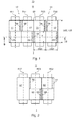
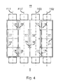
- a first printing unit 01 of a printing press in particular one Rotary printing machine, has a first cylinder 02, z. B. a forme cylinder 02, and an associated second cylinder 03, z. B. a transfer cylinder 03, on (Fig. 1).
- their axes of rotation define R02; R03 is a level E.
- the forme cylinder 02 and the transfer cylinder 03 have on their circumference in Circumferential direction on the lateral surface at least one fault, z. B. an interruption 04; 06 in the effective at unwinding lateral surface.
- This interruption 04; 06 can an impact of a leading and a trailing end of one or more Lifts be, for example, by magnetic force or cohesively on the Scope are arranged. It may, however, also, as in the following in the Embodiments shown to channels 04; 06 or slots 04; Act 06, which pick up the ends of elevators.
- channels 04; 06 designated disturbances are synonymous with other interruptions 04; 06 on the effective lateral surface, d. H. the outward-facing surface of the lifts provided cylinder 02; 03.
- the forme cylinder 02 and transfer cylinder 03 each have at least two channels 04; 06 (or interruptions 03, 04, etc.) on. These two channels 04; 06 are each in Longitudinal direction of the cylinder 02; 03 in a row, and in the circumferential direction to each other staggered.
- the channels 04; 06 are so on the two cylinders 02; 03 arranged that they are at Rotation of the two cylinders 02; 03 each on one of the channels 06; 04 of each another cylinder 03; 04 unroll.
- the offset of the channels 04; 06 each cylinder 02; 03 in the circumferential direction about 180 °.
- the transfer cylinder 01 of the first printing unit 01 forms with a third cylinder 07; over a train 08; z. B. a printing substrate 08, a pressure point 09.
- This third Cylinder 07 can as a second transfer cylinder 07 (Fig. 1) or as a Impression cylinder 07 (FIG. 2), e.g. B. steel cylinder, or satellite cylinder 07th be executed.
- the axes of rotation R03 and R07 of the pressure point 09 forming Cylinder 03; 07 clamp in a pressure-on position AN a plane D (see, for example, Fig. 6 or 13).
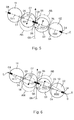
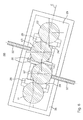
- Fig. 5 are all rotation axis R02; R03; R07; R11 of the four cylinders 02; 03; 07; 11 during printing, d. H. in the print-on position AN in the common plane E or D and run parallel to each other.
- Fig. 6 and 13 shows a corresponding Printing unit 13, wherein in each case a pair of forming and transfer cylinders 02, 03; 11, 07 a plane E, and the transfer cylinder 03; 07 different from the E planes Form level D.
- the cylinders 07; 11 of the second Printing unit 12 channels 04; 06 with the above for the first printing unit 01 described Characteristics regarding the number and the offset to each other.
- the channels 04; 06 the four cylinders 02; 03; 07; 11 are now preferably arranged so that in each case two Channels 04; 06 two cooperating cylinder 02; 03; 07; 11 roll on each other.
- the forme cylinder 02 and the transfer cylinder 03 have an advantageous embodiment each a length L02; L03 on which four or more widths of a printed page, z. B. a newspaper page, z. B. 1100 to 1800 mm, in particular 1500 to 1700 mm and a diameter D02; D03, z. B. 130 to 200 mm, in particular. 145 to 185 mm, whose circumference U corresponds substantially to a length of a newspaper page, in following "single circumference" ( Figures 3 and 4).
- the device advantageous in which the ratio between diameter D02; D03 and length L02; L03 of the cylinder 02; 03 is less than or equal to 0.16, in particular less than 0.12, or even is less than or equal to 0.08.
- each of the two cylinders 02; 03 two channels 04; 06 which each extend continuously over at least one length, which two Widths of a newspaper page corresponds (Fig. 3).
- each of the channels 06 of the transfer cylinder 03 a single, continuous Clamping and / or clamping device or it can - in the case of several Newspaper page widths through channels - in the longitudinal direction one behind the other Clamping and / or clamping devices may be arranged.
- the channels 04 of the forme cylinder For example, 02 also each have a single, or more Clamping devices on.
- both in the channels 04 of the forme cylinder 02; 11 as well as in the Channels 06 of the transfer cylinder 03; 07 used a "minigap technology", being in a narrow channel 04; 06 with inclined leading edge leading end inserted, the elevator on the cylinder 02; 03; 07; 11 wound up is, the trailing end also in the channel 04; 06 is inserted, and the Ends against slipping, z. B. by means of a rotatable spindle or a pneumatic device, to be clamped.
- the transfer cylinder 03; 07 have z. B. in an advantageous embodiment (FIG. 3) only two, circumferentially offset by 180 ° to each other elevators, which each have at least one width, which two widths of a newspaper pages equivalent.
- the elevators or channels 04 of the forme cylinder 02 run; 11 Complementary to this and must either, as shown, two continuous, respectively a length of two newspaper page widths having channels 04, or in pairs adjacent and aligned channels 04, each with a length of one Have newspaper page width.
- the form cylinder 02; 11 are in an advantageous embodiment with four in the longitudinal direction of Forme cylinder 02; 11 juxtaposed bendable elevators occupied, which in Circumferential direction a length of slightly over the length of the printed image of a Newspaper page, and in the longitudinal direction have a width of about one newspaper page.
- This highly symmetrical arrangement leaves In addition, reduce the risk of vibration excitation in the plane E or avoid, which is due to the non-simultaneous passage of the channels 04; 06 on Page I and page II. Also mutually on page I and page II alternately tensioning and relaxing the web 08, and thereby causing it Swinging the web 08 can be avoided.
- the Forme cylinder 02; 11 in an advantageous embodiment with respect to their axes of rotation R02; R11 firmly arranged.
- the Transfer cylinder 03; 07 moves while the forme cylinder 02; 11 in their fixed, possibly remain previously adjusted position.
- the forme cylinder 02; 11 however in corresponding devices, eg. B. in eccentric or Doppelexzenterbuchsen, in Linear guides or levers to be stored.
- the transfer cylinder 03; 07 can, as in Figs. 5 to 7 schematically, as well as in Fig. 8 to 11 shown in more detail, along a linear travel 16, or as in Figs. 12 and 13 schematically and in Figs. 14 and 15 shown in more detail, along a curved travel 17 be movable. Stellweg 16 and 17 and the Transfer cylinder 03; 07 in a pressure-off position AB are shown in Figs. 5, 6 and 12th shown in dashed lines.
- the travel 16; 17 by the Storage of the transfer cylinder 03; 07 in eccentric bushes not shown, especially in double eccentric bushings.
- double eccentric bushes can be in the area of the pressure-on position AN a substantially linear travel 16, in the of the Pressure point 09 more distant range, however, if necessary, a curved travel 17th generate, which a faster or greater shutdown of the transfer cylinder 03; 07 from the cooperating transfer cylinder 07; 03 as from the assigned Forme cylinder 02; 11 or vice versa.
- eccentrics is also for the use of eccentrics.
- Figures 5 to 11 are embodiments of the printing unit 01; 12 set forth, wherein at least one of the transfer cylinder 03; 07 along a linear Travel path 16 is movable (Fig. 5):
- the linear travel 16 takes place by means of linear guides not shown in FIG. 5, which are arranged in or on in Fig. 5 also not shown side frame.
- the bearings in a linear guide are made for the robust and low-vibration Construction preferably on page I and on page II of the double printing unit 13.
- FIG. 5 the course of the web 08 is located by the in-pressure ON position Print point 09 shown.
- the plane E of the double printing unit 13 (FIG. 5) or of the respective printing unit 01; 12 (FIG. 6) and the plane of the web 08 intersect in FIG advantageous embodiment at an angle ⁇ of 70 ° to 85 °.
- Transfer cylinder 03; 07 on a circumference which is the length of about one Newspaper page corresponds, so the angle ⁇ z. B. about 75 ° to 80 °, preferably about 77 °; have the transfer cylinder 03; 07 but on a circumference, which in about the Length of two newspaper pages corresponds, so the angle ⁇ z. B. 80 to 85 °, preferably about 83 °.
- This choice of angle ⁇ contributes to the safe and fast Cropping the web 08 and / or stopping the transfer cylinder 03; 07 from each other with minimized travel 16 bill, and minimized to another negative Influences on the print result, which are due to the extent of a partial wrap the or the transfer cylinder 03; 07 is significantly influenced (doubling, Lubrication etc.).
- the required linear travel 16 is each Transfer cylinder 03; 07 is less than or equal to 20 mm for the on / off of the Transfer cylinder 03; 07 to each other / from each other, for an exemption of the train 08 in an imprint mode, however, up to 35 mm.
- the angle ⁇ is between Travel path 16 and the plane of the web 08 preferably greater than or equal to 5 °, z. B. between 5 ° and 30 °, in particular between 5 ° and 20 ° to "Währe
- the angle ⁇ is in particular for forme cylinder 02; 03; 07; 11 simple circumference greater than or equal to 10 °.
- the angle ⁇ is limited so that the angle ⁇ between the in the direction Forme cylinder 02; 11 facing part of the plane E and the direction of the Abstellweges 16 at least 90 °. So is a quick and safe shutdown of the Transfer cylinder 03; 07 simultaneously from the railway 08 and the associated Forme cylinder 02; 11 guaranteed.
- the direction of the travel 16 (in the direction of shutdown) is selected so that an angle ⁇ between the plane D and the travel 16 in the direction of shutdown at least 90 ° and at most 120 °, in particular from 90 ° to 115 ° is.
- the angle ⁇ is again limited upwards so that the angle ⁇ is at least 90 °.
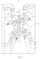
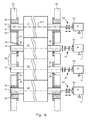
- the double printing unit 13 is multiply, as shown in Fig. 7, for example, twice, in a printing unit 19, z. B. a so-called. H-printing unit 19, in a common Side frame 20 can be used.
- Fig. 7 was on the separate name of the upper double printing unit 13 similar parts for each below Double printing unit 13 omitted.
- This is of course also for individual printing units 01; 12, for double printing 13 and for different configured printing units, which several printing units 01; 12 have.
- the priority instead of a saving in height h can also be improved Accessibility of the cylinder 02; 03; 07; 11, z. B. for the purpose of changing elevators, Cleaning and washing, maintenance, etc., lie.
- the pressure on or off position AN; AB is in all figures for clarity shown oversubscribed.
- Fig. 7 indicates in dashed lines the transfer cylinder 03; 07 in one second possible location along the linear travel 16, which here
- the upper double printing unit 13, z. B. for the printing plate change in the Print-off position AB (solid)
- the lower double printing unit 13, z. B. for continued pressure, in the pressure on position ON (solid) is operated.
- each of the printing units 01; 12 at least one own, but in Fig. 7 only indicated by dashed lines drive motor 14 for the rotary drive of the cylinder 02; 03; 07; 11 on.
- the drive by the drive motor 14 takes place in an advantageous embodiment in each case coaxially between axis of rotation R02; R03; R07; R11 and motor shaft, if necessary with an angle and / or offset compensating, explained in more detail below coupling. He can if one "Moving" of the drive motor 14 or a flexible coupling between the Drive motor and the possibly to be moved cylinder 02; 03; 07; 11 avoided should, but also be done via a pinion.
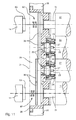
- a first embodiment for the realization of the linear travel 16 by means Linear guide show Figs. 8 and 9.
- the pin 23 at least one of the transfer cylinder 03; 07 are for example in As carriage 24 running bearing housings 24 rotatably mounted in radial bearings 27 (in 8 and 9, only the arrangement in the region of an end face of the cylinder 02; 03; 07; 11 ) Shown.
- the bearing housing 24 and slide 24 are in linear guides 26th movable, which are connected to a side frame 27.
- two linear guides 26 are provided, which are parallel to each other.
- the linear guides 26 of two adjacent transfer cylinder 03; 07 run preferably parallel to each other.
- the linear guides 26 can directly in an embodiment, not shown Walls of the side frame 27, in particular on walls of openings in Side frame 27 may be arranged, which is almost perpendicular to the end face of the cylinder 02; 03; 07; 11 run.
- the side frame 27 in an opening an insert 28, z. B. a so-called. Bell 28, on.
- the linear guides 26 are on or in this bell 28 is arranged.
- the bell 28 has an area which in the direction Cylinder 02; 03; 07; 11 emerges from the escape of the side frame 27.
- the Linear guides 26 are arranged in or on this area of the bell 28.
- the distance between the two opposite side frames 20 (only one i) is oriented. d. R. on the widest aggregate, z. B. at the wider inking unit 21, and usually causes a correspondingly longer pin on the cylinders 02; 03; 07; 11.
- Arrangement is that the pins of the cylinder 02; 03; 07; 11 can be kept as short as possible.
- the bell 28 has in a development on a cavity 29, at least partially in the amount of the escape of the side frame 20 is arranged.
- this cavity 29 are, as shown schematically in Figure 9, the rotary drives of the cylinder 02; 03; 07; 11 with the pins of the cylinder 02; 03; 07; 11 connected.
- Particularly advantageous pairwise drive the cylinder 02; 03; 07; 11 can also drive connections, such. B. cooperative drive wheels 30, be accommodated in this cavity 29.
- On the transfer cylinder 03; 07 can be in Advantageous design (Fig. 9) with frame-mounted drive motor 14 between Transfer cylinder 03; 07 and drive motor 14 an angle and offset Balancing coupling 61 may be arranged to the arrival and Abstellterrorism of Transfer cylinder 03; 07 balance.
- This can be used as a double joint 61 or in an advantageous embodiment as all-metal coupling 61 with two torsionally rigid but axially be designed deformable plate packs.
- the all-metal coupling 61 can at the same time compensate for the offset and the resulting change in length. It is essential that the rotational movement is transmitted without play.
- the coupling 62 is at least a slight angle and offset compensating coupling 62 executed.
- This is also advantageous Version as all-metal coupling 62 with two torsionally rigid but axially deformable Disc packs executed. The linear motion is through the in the axial direction positively connected to the pin 51 and a shaft of the drive motor 14 Lamella packages added.
- the Cavity 29 in a simple manner by means of a cover 31 (dashed lines) limited, without that this increases the width of the machine or from the side frame 20th protrudes.
- the cavity 29 can then be carried out encapsulated.
- the arrangement of the bell 28 thus shortens the length of the pins, which is a reduction vibration and allows a simple and variable construction, which are suitable for a wide variety of drive concepts, and more extensive Identity equality the change between the concepts - with or without Drive connections, with or without lubricant, with or without additional Couplings - allowed.
- the drive of the respective bearing housing 24 or carriage 24 in the linear guides 26 takes place in the embodiment shown schematically in Fig. 8 z. B. by means of linear Drives 32, z. B. in each case a screw drive 32, z. B. a threaded spindle, which of an electric motor, not shown, is driven.
- the electric motor can here be adjustable with respect to a rotational position.
- AN can be a frame-fixed, but adjustable stop for the bearing housing 24th be provided.
- the drive of the bearing housing 24 but also by means of a lever mechanism respectively.
- This can also by means of an electric motor or by means of at least be driven by a pressurizable cylinder.
- Will the Lever mechanism by means of one or more acted upon by pressure medium Cylinder driven, so the arrangement of the adjusting movement on the two sides I and II synchronizing synchronous spindle advantageous.
- connection of the transfer cylinder 03 to be moved; 07 to the side frame 20 or the bell 28 is executed in the embodiment of FIG. 9 as follows:
- the bell 28 On both sides of leading to carriage 24, the bell 28 has support walls 33, which one of the two corresponding parts of the linear guide 26 receives. this part If necessary, it may also already be part of the supporting wall 33, or be incorporated into it.
- the other corresponding part of the linear guide 26 is arranged on the carriage 24 or incorporated in this or having this.
- Carriage 24 through two such, on two opposite sides of the carriage 24 arranged linear guides 26 out.
- the on the support walls 33 (or without bell 28 directly on the side frame 20) arranged parts of the guides 26 so include the arranged between them Slide 24.
- the active surfaces of the side frame 20 and the bell 28th connected parts of the linear guide 26 point in the pin 23 facing Half space.
- the two parts of the two guides 26 leave a motion in the ideal state of the carriage 24 with only one degree of freedom as a linear movement. For this is the entire arrangement in a direction perpendicular to the axis of rotation R03; R07 and perpendicular to Movement direction of the carriage 24 lying direction against each other substantially tensioned free of play.
- the respective formzylindernahe part of the leadership (In Fig. 9 with larger size) on a tensioning device, not shown.
- the mounted in the manner described slide 24 has, for. B. on a radially to Inside facing side of the transfer cylinder 03; 07 facing Recess, the pin 23 receiving radial bearing 27.
- these parts are the Linear guide on one with the bell 28 (or the side frame 20) connected Carrier 36 is arranged.
- the carriage 24 has its associated parts of Linear guide 26 in a side frame 20 and the bell 28 facing Recess on. These parts can be arranged in the recess as components, or but in the carriage 24 in an inwardly facing surface of the recess already be incorporated.
- FIG. 10 and 11 the active surfaces of the with the side frame 20 and the bell 28 connected parts of the linear guide 26 in the pin 23 facing away from the half space.
- these parts are the Linear guide on one with the bell 28 (or the side frame 20) connected Carrier 36 is arranged.
- the carriage 24 has its associated parts of Linear guide 26 in a side frame 20 and the bell 28 facing Recess on. These parts can be arranged in the recess as components, or but in the carriage 24 in an inwardly facing surface
- the carriage 24 has a to the transfer cylinder 03; 07 facing recess, in which the radial bearing 27 is arranged for receiving the pin 23.
- the radial bearing 27 is arranged for receiving the pin 23.
- the present embodiment is a running surface for rolling elements of the bearing 27 designed as a radial bearing 27th already incorporated in an inwardly directed surface of the recess.
- the arranged on the carriage 24 parts of the guides 26 so include the carrier 36, or the parts arranged on the carrier 36, on the side frame 20 or on the bell 28 the guides 26.
- At least one of the two the transfer cylinder 03; 07 associated carrier 36th has an embodiment oriented in the direction of movement of the carriage 24, not in the figures visible slot for the implementation of the linear to be moved Pin 23 on.
- This slot is at least partially aligned with one also not visible, in the bell 28 (or in the associated side frame 20) arranged Long hole.
- These slots are from the pin 23 or one with the pin 23rd connected shaft, which for the rotary drive of the Transfer cylinder 03; 07 with a drive wheel 30 (see Fig. 9) or the Drive motor 14 is in drive connection.
- Fig. 11 shows the embodiment via a lever mechanism executed actuating means.
- the carriage 24 is articulated via a coupling 37 with a lever 38 connected, which about a substantially parallel to the axis of rotation R03; R07 the transfer cylinder 03; 07 extending axis is pivotable. in the Embodiment are for synchronizing the adjusting movement of both Transfer cylinder 03; 07, the coupling 37 of the two adjacent carriages 24 for cooperating transfer cylinder 03; 07 with the here as three-armed lever 39 executed lever 38 hinged.
- the drive of the lever 38 takes place by means of at least one actuator 39, z.
- the arrangement of stops 41 is advantageous against which the respective carriage 24 is set in the pressure-on position AN.
- These attacks are made adjustable to adjust the end position for the transfer cylinder 03; 07 to allow in which their axes of rotation R03; R07 lie in the plane E come.
- the system becomes very stiff when the carriage 24 against the stop 41, or the stoppers 41 (in each case two in FIG. 10) is pressed with great force.
- Figures 8 to 11 may be an adjustment be provided, which, in particular during assembly and / or when Configurations and / or conditions have changed, a default setting for the Spacings of the axis of rotation R02; R03; R07; R11 allows.
- individual the cylinder 02; 03; 07; 11, z. B. the forme cylinder 02; 11, possibly in an eccentric bushing be stored.
- at least one of the transfer cylinder 03; 07 can to Adjustment be adjustable in a radial direction.
- the Side frame 20 and the bell 28 associated parts of the linear guides 26 or Carrier 36 in sufficient for adjustment purposes oblong holes with the side frame 20th or the bell 28 may be connected.
- an eccentric and lockable storage the radial bearing 27 in the carriage 24 is possible.
- Figures 12 to 18 are embodiments of the printing unit 01; 12 set forth, wherein at least one of the transfer cylinder 03; 07 along a curved travel path 17 is movable (Fig. 12):
- the lever 18 shown schematically in Fig. 12 is one of the transfer cylinder 03rd pivotally mounted about a pivot axis S.
- the pivot axis S is here z.
- the lever 18 in this case has a length between the storage of Rotation axis R03; R07 of the transfer cylinder 03; 07 and the pivot axis S which is larger than the distance of the rotation axis R03; R07 of the Transfer cylinder 03; 07 from the axis of rotation R02; R11 of the assigned Forme cylinder 02; 11 in pressure ON position. This is a simultaneous shutdown of co-acting transfer cylinder 03; 07 and the associated Forme cylinder 02; 11, and vice versa for hiring.
- pivot axis S can in particular also, as described in more detail below, in otherwise eccentric to the axis of rotation R02; R11 of the assigned Forme cylinder 02; 11, z. B. at a distance to the plane E, be arranged.
- the Storage in a lever 18 is preferably carried out on page I and on page II of Double printing unit 13.
- FIG. 12 and 13 the course of the web 08 by the in pressure on position AN located pressure point 09 shown.
- ⁇ 70 ° to 85 °.
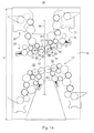
- the double printing unit 13 (here in linear design) is multiple, as in FIG. 14 represented, for example, twice, in a printing unit 19, z. B. the so-called. H-printing unit 19, in the common side frame 20 can be used.
- Fig. 14 was on the separate Designation of the upper double printing unit 13 equivalent parts for each bottom double printing unit 13 omitted. Among the advantages of this arrangement is refer to the comments on Fig. 7.
- Fig. 13 indicates by dashed lines (but overdrawn for clarity) the Transfer cylinder 03; 07 in a second possible position along the travel path 17th to, for example, the upper double printing unit 13, z. B. for Printing form change, in the print-off position AB, and the lower double printing unit 13, z. B. for continued printing, is operated in the print-on position ON.
- each of the printing units 01; 12 at least one own drive motor 14 for the rotary drive of the cylinder 02; 03; 07; 11 on.
- the printing unit 01; 12 in one Version with its own, and of the other drives mechanically independent drive motor 14 per cylinder 02; 03; 07; 11 over a high level Flexibility (Fig. 14 indicated by dashed lines for upper double printing unit 13).
- FIG. 14 top or bottom
- the type of drive from FIG. 14 are shown by way of example and thus to the respective other printing units 01; 12 or the other double printing 13 to transfer.
- the drive by the drive motor 14 takes place in an advantageous embodiment in each case coaxially between axis of rotation R02; R03; R07; R11 and motor shaft, possibly above the above closer, angle and / or offset compensating couplings 61; 62.
- the Drive if a "co-moving" of the drive motor 14 or a flexible coupling between the drive motor and the possibly to be moved cylinder 02; 03; 07; 11 should be avoided, but also done via a pinion.
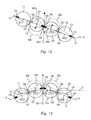
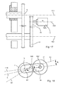
- Fig. 15 shows a side view, wherein two of each frontally on Transfer cylinder 03; 07 (dashed) arranged pin 23 only one is visible.
- the lever 18 is pivotally mounted about the pivot axis S, which preferably with respect to the side frame 20 fixed (but possibly adjustable) is.
- the rotation axes R02; R03; R07; R11 of the cylinder 02 shown in broken lines; 03; 07; 11 are in the illustrated embodiment in print-on position again in a plane E, which here with the plane D between the pressure point 09 forming cylinders 03; 07 coincides.
- the pivot axis S of the lever 18 is eccentric to the rotation axis R02; R11 of the Forme cylinder 02; 11 is located and lies outside the plane E or D.
- the toggle mechanism 46 is hinged to the lever 18 and connected to a frame-fixed pivot point.
- Advantageously double acting pressure cylinder acts z.
- the drive and adjusting means 44; 46 are designed and arranged such that a Parking the transfer cylinder 03; 07 each in the direction of the obtuse angle ⁇ (for straight web run 180 ° - ⁇ ) takes place between web 08 and level D or E.
- the eccentricity e-S of the pivot axis S to the rotation axis R02; R11 of the Forme cylinder 02; 11 is between 7 and 15 mm, in particular about 9 to 12 mm.
- the Eccentricity e-S is in Anstelllage the transfer cylinder 02; 03; 07; 11, d. H.
- the Rotation axes R03; R07 are in the o. G.
- the rotation axis R02; R11 of the forme cylinder 02; 11 is adjustable, z. B. also eccentric to its attachment to the side frame 20, here to a bore 49, stored.
- a pin 51 of the forme cylinder 02; 11 in one Eccentric 52 and an eccentric bushing 52 arranged, which in the Bore 49 is pivotally mounted.
- a pivot axis S51 of the forme cylinder 02; 11 is an eccentricity of 5 to 15 mm, in particular about 7 to 12 mm eccentric to the axis of rotation R02; R11 of the Forme cylinder 02; 11 is located and lies outside the level E.
- the eccentricity e-S51 is in strom of form and associated Transfer cylinder 02, 03; 11, 07, d. H.
- the axes of rotation R02, R03 and R11, R07 lie in the plane E, oriented so that an angle s-S51 between the plane E of Pair of cylinders 02, 03 and 11, 07 and a connecting plane of the pivot axis S51 and the rotation axis R02; R11 of the forme cylinder 02; 11 between 25 ° and 65 °, advantageously between 32 ° and 55 °, in particular between 38 ° and 52 °.
- the pivot axis S5 is preferably in a half-plane which is farther from the axis of rotation R03; R07 the associated transfer cylinder 03; 07 as the rotation axis R02; R11 of the associated forme cylinder 02; 11 is located.
- the pivot axis S51 for the eccentric mounting of the forme cylinder 02; 11 falls in the Embodiment with the pivot axis S of the lever 18 together.
- pivot axis S and S51 are not mandatory, however appropriate.
- the lever 18 could also on an eccentric flange of the journal 51 receiving bearing bushing 52nd be arranged, but when twisting a simultaneous adjustment of the distances between Form 02; 11 and transfer cylinder 03; 07 as well as between the Transfer cylinders 03; 07 would result.
- the two pivot axis S51 are in the pressure ON position AN (and / or S) and S23 of a pair of forming and transfer cylinders 02, 03; 11, 07 arranged on two different sides of the plane E.
- the rotation axes R03; R07 lie in the plane D, so oriented, that an angle ⁇ -S23 between the plane D and the connection plane of Swivel axis S-23 and axis of rotation R07 (R03) between 70 ° and 110 °, is advantageously between 80 ° and 100 °, in particular between 85 ° and 95 °.
- the angle ⁇ -S23 should be approx. 90 °
- Fig. 16 is an embodiment of FIG. 15 in a representation of a section given along the plane E.
- the pins 51 of the forme cylinder 02; 07 are each in Bearings 54, z. B. bearings 54 rotatably mounted.
- the Bearings 54 are arranged in eccentric bearing 52 and eccentric bearing bush 52, respectively. which in turn is pivotally mounted in the bore 49 in the side frame 20. It can in addition to the eccentric bushing 52 and the bearing 54 even more Bearing rings and sliding or rolling bearings between the bore 49 and pin 51 are arranged be.
- the lever 18 is on a forme cylinder 02; 07 out of the side frame 20 projecting part of the bearing bush 52, and pivotally mounted relative to this.
- the Lever 18 takes in its the pivot axis S far end of the pin 23 of the Transfer cylinder 03; 07, which rotates in a bearing 56, and this in the Case of the transfer cylinder 07, about the pivot axis S-23 pivotable in one Eccentric bearing 57 or in an eccentric bushing 57 is arranged.
- a Such pivotable bushing 57 may optionally also for both as needed Transfer cylinder 03; 07 be arranged.
- the side frame 20 recesses 58, in which the pin 23 of the transfer cylinder 03; 07 are pivotable.
- the adjusting means 46; 53 and drive means 44 are not in Fig. 8 shown.
- the rotary drive of the cylinder 02; 03; 07; 11 takes place by means of own, mechanically from the drive of the other cylinder 02; 03; 07; 11 independent Drive motors 14, which are preferably arranged fixed to the frame.
- the latter has the Advantage that the drive motors 10 need not be moved.
- the angle and offset compensating Coupling 61 arranged, which as a double joint 61 or in an advantageous Execution be executed as all-metal coupling 61.
- the all-metal coupling 61 simultaneously equalizes the offset and the resulting change in length, where the rotational movement is transmitted without play.
- the drive of the forme cylinder 02; 11 points between pin 51 and drive motor 14, the at least one axial relative movement between cylinder 02; 11 and Drive motor 14 receiving coupling 62, which in order to also manufacturing tolerances and possibly required adjustment movements of the forme cylinder 02; 11 for adjustment purposes to be able to absorb, at least slight angles and offset compensating can be executed.
- All-metal coupling 62 executed, which the axial movement through the axial Direction positively with the pin 51 and a shaft of the drive motor 14th accommodates connected plate packs.
- a pairwise drive may also be provided by the Drive motor (possibly via other transmission parts not shown) by a pinion 59 on a drive wheel 61 of the transfer cylinder 03; 07 occur when, for example, a special moment flow ß to be achieved.
- a rotation axis R59 of the pinion 59 is then preferably fixed to the frame in this way arranged one of the axis of rotation R59 of the pinion 59 and the Pivoting axis S of the lever 18 fixed straight line G1 with one of the pivot axis S of the lever 18 and the rotation axis R03; R07 of the transfer cylinder 03; 07 plane E18 defined an opening angle ⁇ in the range of + 20 ° to -20 ° includes.
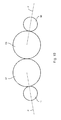
- the aforementioned embodiments for driving and for moving the Transfer cylinder 03; 07 and the execution of the lever 18 and the Linear guide 26 are equally applicable to printing units, in which the cylinder 02; 03; 07; 11 do not all have the same circumference or diameter (FIG. 19). So can or can in particular the or the forme cylinder 02; 11 a circumference U have, which in the circumferential direction a pressure side, z. B. the long side of a Newspaper page (hereinafter "single circumference").
- the cooperative Transfer cylinder 03; 07 has z. B. a circumference or diameter, which an integer multiple (greater than 1) of that of the forme cylinder 02; 11 corresponds, d. H. he has z. B. a circumference of two or even three printed pages in Newspaper format (or adapted to other formats).
- the cylinders 02; 03; 07; 11 may be described for all embodiments as described either in pairs or individually by their own drive motor 14 be driven.
- a drive is possible, wherein one of the forme cylinder 02; 11 of a printing unit 01; 12 own drive motor 14, and the remaining cylinders 02; 03; 07; 11 of the printing unit 01; 12 a common Drive motor 14 have.
- a configuration of four or five cylinders 02; 03; 07; 11 with three drive motors 14 may be advantageous: In the case of a double printing unit 13 z. B.
- each pair of forming and transfer cylinder 02; 03; 07; 11 one and for the Satellite cylinder a separate drive motor 14.
- the four cylinders 02; 03; 07; 11 in pairs by a drive motor 14 depending on the requirements of Forme cylinder 02; 11 or from the transfer cylinder 03; 07 rotationally driven.
- Each forming a gear drive wheels 30 between the forme cylinder 02; 11 and the respective associated transfer cylinder 03; 07 form each with the associated drive motor 14 a drive connection.
- the two pairs of Drive wheels 30 are preferably arranged to disengage from each other what, for example, by axially offset arrangement, d. H. in two Drive levels, done.
- the latter also applies to a possibly arranged pinion between the drive motor 14 and the Drive wheel of the forme cylinder 02; 11, when the pair on the forme cylinder 02; 11 not is coaxially driven.
- a cooperating pair of links in the Drive connection between drive motor 14 and forme cylinder 02; 11 straight teeth and against each other to be axially movable to the axial movement of the Forme cylinder 02; 11 without ensuring simultaneous rotation.
- the in Fig. 9 and 11 illustrated drive situations are shown on the two To transfer versions for the realization of the linear motion reciprocal.
- the drive motors 14 are in an advantageous embodiment arranged frame-fixed. If a cylinder 02; 03; 07; 11 driving drive motor 14 deviating from this, however, be arranged fixed to the cylinder, so he can during the Adjusting movement and / or adjustment of the cylinder 02; 03; 07; 11 in a variant also on an appropriate (or the same) leadership or a corresponding lever, z. B. on an outer side of the side frame 20, entrained become.
- FIGS. 9 and 16 in the embodiment with a frame-fixed drive motor 14, which on the transfer cylinder 03; 07 (the individually or pairwise driven cylinders 02; 03; 07; 11) drives, it is advantageous as shown in FIGS. 9 and 16 by way of example, the angle and Offset compensating coupling 61 to be arranged.
- FIGS. 9, 11 and 16 shown by way of example has coaxially driven forme cylinder 02; 11 the drive the described coupling 62 between pin 51 and drive motor 14.
- the drive motor 14 is in each case advantageous as an electric motor, in particular as Asynchronous motor, synchronous motor or designed as a DC motor.
- a transmission 63 is arranged between each of the drive motors 14 and the to be driven cylinder 02; 03; 07; 11, a transmission 63 is arranged.
- This transmission 63 can a connected to the drive motor 14 attachment gear 63, z. B. a Be planetary gear 63. However, it can also be run as a different way Reduction gear 63, z. B. pinion or belt and drive wheel, be executed.
- each transmission 63, z. B. as individually encapsulated Actuator gear 63.
- the lubricant spaces thus generated are spatially limited and prevent the pollution of adjacent machine parts and contribute to Increasing the quality of the product.
- the drive units each specifically encapsulated, d. H. to run with its own lubricant space.
- An o. G. individual encapsulation extends, for example, to the pairwise drive of two Cylinder 02, 03; 11, 07 or else - especially in the case of the bell described above 28 - around both pairs.
- a bell 28 may also each be for a pair of two cylinders 02; 03; 07; 11 executed. The latter is, for example, in the sense of a Modularization of advantage.
- the respective form cylinder 02; 11 associated inking unit 21 and, if available, the associated dampening unit 22 of one, from the drive of the printing cylinder independent drive motor is rotationally driven.
- that can Inking unit 21 and any existing dampening unit 22 each have their own Drive motor have.
- the one or more distribution cylinders may or may be separate or groupwise rotationally driven.
- the or the distribution cylinder of a Dampening units 22 can or can be driven individually or in groups in a rotary manner be.
- a high variability has the double-width printing machine simple scope especially in the gradation of possible page numbers in the product, in the so-called. "Escapade". While the thickness per booklet (lay) for the printing machine with double Scope and simple width in collective operation (ie maximum product strength) only can be varied in steps of four printed pages, leaves the double-width described Printing machine simple circumference an "infidelity" from two sides (eg Newsprint) too. The product strength and in particular the "distribution" of the printed pages to different folders of the total product or products is considerably more flexible.
- the partial web is thus either on a to the corresponding part web different former and / or folder led, or she is turned on the flight of the latter.
- the sub-web before, during or after turning but before merging with the "straight lines", brought into the correct longitudinal or cutting register.
- This is in dependence of circumferentially offset channels 04; 06 one Cylinder 02; 03; 07; 11 in an advantageous embodiment by corresponding embodiment of Turning corners (eg preset distances of the bars or the path sections) considered.
- the fine adjustment or regulation is with the positioning of the Cut register control for the relevant partial web and / or partial web strand made to partial webs of two different levels if necessary match each other.
- the form cylinder 02; 11 is now in the circumferential direction with one and in the longitudinal direction with at least four stationary printed pages in broadsheet format (Fig. 20).
- this form cylinder 02; 11 also optionally in the circumferential direction with two and in the longitudinal direction with at least four lying printed pages in tabloid format (FIG. 21) or in the circumferential direction with two and in the longitudinal direction with at least eight stationary printed pages in book format (FIG. 22) or in the circumferential direction with four and in Longitudinal direction with at least four lying printed pages in book format (Fig. 23) by means of in the circumferential direction of the forme cylinder 03 one and the longitudinal direction at least one can be fitted on this flexible, flexible printing plate.
- the double printing unit is in a four-page printed pages in broadsheet format corresponding web width for the production of two each from one layer existing broadsheet format products with four printed pages in one product and four printed pages in the other product or two printed pages in the one Product and six printed pages in the other product is usable.
- a three standing printed pages corresponding web width is for the production of each Two four-page broadsheet-format products in one layer one product and two printed pages in the other product.
- the double printing unit 13 at a four-sided printed pages in Broadsheet format corresponding web width for the production of one of two layers existing product in broadsheet format with four printed pages in one layer and four printed pages in the other layer or two printed pages in one layer and six Print pages in the other position usable.
- a three-sided printed pages corresponding web width it is for the production of a two-layer existing Product in broadsheet format with four printed pages in one layer and two Print pages in the other position usable.
- the double printing unit 13 is at a four, three or two lying Print pages or a lying print page corresponding web width for the Making one of a layer in the above order with sixteen or twelve or eight or four printed pages of existing product in tabloid format usable.
- the double printing unit is in tabloid format for four printed pages corresponding web width for the production of two each from one layer existing products in tabloid format with eight printed pages in one product and eight printed pages in the other product or four printed pages in the one product and twelve printed pages in the other product.
- a three-lying Printing pages corresponding web width it is sufficient for the production of two each a layer of existing products in tabloid format with four printed pages in one Product and eight printed pages in the other product suitable.
- Double printing unit 13 is at one eight, six or four or two stationary Printing pages corresponding web width producing one from a location in the preceding order with thirty-two, twenty-four, and sixteen, respectively or eight printed pages of existing product in book format possible.
- Double printing unit 13 for the production of two each consisting of one layer Book-sized products with sixteen printed pages in one product and sixteen Printed pages in the other product or twenty four printed pages in one Product and eight printed pages in the other product suitable.
- a six standing printed pages in book format corresponding web width it is for the Production of two single-layer products in book format with sixteen printed pages in one product and eight printed pages in the other Product suitable.
- a four or three or two lying pressure sides or a lying pressure side in book format corresponding web width is the double printing unit 13 for the Making one out of a layer in the preceding order with thirty-two or twenty-four or sixteen or eight printed pages of existing product in the Book format usable.
- the double printing unit is in book format for a four-page printed pages corresponding web width for the production of two each from one layer existing products in book format with sixteen printed pages in the one product and sixteen printed pages in the other product and twenty-four printed pages in one product and eight printed pages in the other product.
- a three lying printed pages in book format corresponding web width it is for the Production of two single-layer products in book format with sixteen printed pages in one product and eight printed pages in the other Product suitable.
Landscapes
- Mechanical Engineering (AREA)
- Engineering & Computer Science (AREA)
- Rotary Presses (AREA)
- Feeding Of Articles By Means Other Than Belts Or Rollers (AREA)
- Supply, Installation And Extraction Of Printed Sheets Or Plates (AREA)
- Printing Methods (AREA)
- Manufacturing Of Printed Wiring (AREA)
- Printers Or Recording Devices Using Electromagnetic And Radiation Means (AREA)
- Electrostatic Charge, Transfer And Separation In Electrography (AREA)
- Handling Of Sheets (AREA)
- Character Spaces And Line Spaces In Printers (AREA)
- Inking, Control Or Cleaning Of Printing Machines (AREA)
- Perforating, Stamping-Out Or Severing By Means Other Than Cutting (AREA)
- Application Of Or Painting With Fluid Materials (AREA)
- Sewing Machines And Sewing (AREA)
- Bearings For Parts Moving Linearly (AREA)
- General Factory Administration (AREA)
- Screen Printers (AREA)
Applications Claiming Priority (6)
| Application Number | Priority Date | Filing Date | Title |
|---|---|---|---|
| DE10117703 | 2001-04-09 | ||
| DE10117703 | 2001-04-09 | ||
| DE10138221 | 2001-08-03 | ||
| DE10138221 | 2001-08-03 | ||
| EP02740233A EP1377453B2 (fr) | 2001-04-09 | 2002-04-06 | Groupe d'impression d'une machine d'imprimerie |
| EP03103401A EP1375137B1 (fr) | 2001-04-09 | 2002-04-06 | Groupe d'impression d'une machine d'imprimerie |
Related Parent Applications (1)
| Application Number | Title | Priority Date | Filing Date |
|---|---|---|---|
| EP03103401A Division EP1375137B1 (fr) | 2001-04-09 | 2002-04-06 | Groupe d'impression d'une machine d'imprimerie |
Publications (3)
| Publication Number | Publication Date |
|---|---|
| EP1543964A2 true EP1543964A2 (fr) | 2005-06-22 |
| EP1543964A3 EP1543964A3 (fr) | 2006-05-03 |
| EP1543964B1 EP1543964B1 (fr) | 2009-06-17 |
Family
ID=26009050
Family Applications (20)
| Application Number | Title | Priority Date | Filing Date |
|---|---|---|---|
| EP03103416A Withdrawn EP1378350A3 (fr) | 2001-04-09 | 2002-04-06 | Groupe d'impression d'une machine d'imprimerie comportant un cylindre de transfert pouvant être déplacé linéairement |
| EP03103411A Withdrawn EP1371485A3 (fr) | 2001-04-09 | 2002-04-06 | Groupe d'impression d'une machine d'imprimerie comportant un cylindre de transfert pouvant être déplacé linéairement |
| EP02742673A Expired - Lifetime EP1377456B1 (fr) | 2001-04-09 | 2002-04-06 | Groupe d'impression d'une machine d'imprimerie comportant un cylindre de transfert basculable |
| EP03103427A Expired - Lifetime EP1378351B1 (fr) | 2001-04-09 | 2002-04-06 | Groupe d'impression d'une machine d'imprimerie comportant un cylindre de transfert pivotant |
| EP03104076.9A Expired - Lifetime EP1393900B1 (fr) | 2001-04-09 | 2002-04-06 | Machine d'impression |
| EP03103407A Expired - Lifetime EP1375139B1 (fr) | 2001-04-09 | 2002-04-06 | Groupe d'impression d'une machine d'imprimerie comportant un cylindre de transfert pouvant être déplacé linéairement |
| EP07101553A Expired - Lifetime EP1775123B1 (fr) | 2001-04-09 | 2002-04-06 | Imprimé d'une presse |
| EP05101366A Expired - Lifetime EP1543964B1 (fr) | 2001-04-09 | 2002-04-06 | Unité d'impression pour une machine à imprimer |
| EP07101541A Expired - Lifetime EP1775125B1 (fr) | 2001-04-09 | 2002-04-06 | Imprimé d'une presse |
| EP02740232A Expired - Lifetime EP1377452B1 (fr) | 2001-04-09 | 2002-04-06 | Groupe d'impression d'une machine d'imprimerie comportant un cylindre de transfert pouvant etre deplace lineairement |
| EP03103432A Withdrawn EP1378352A3 (fr) | 2001-04-09 | 2002-04-06 | Groupe d'impression d'une machine d'imprimerie comportant un cylindre de transfert pivotant |
| EP03103443A Withdrawn EP1384579A3 (fr) | 2001-04-09 | 2002-04-06 | Elément d'impression d'une machine à imprimer comportant un cylindre de transfert pivotant |
| EP03103401A Expired - Lifetime EP1375137B1 (fr) | 2001-04-09 | 2002-04-06 | Groupe d'impression d'une machine d'imprimerie |
| EP03103402A Withdrawn EP1375138A3 (fr) | 2001-04-09 | 2002-04-06 | Groupe d'impression d'une machine d'imprimerie et procédé de réalisation d'un produit imprimé |
| EP02742671A Expired - Lifetime EP1377454B1 (fr) | 2001-04-09 | 2002-04-06 | Element d'impression d'une machine a imprimer presentant un cylindre de transfert pivotant |
| EP05100307A Withdrawn EP1541347A3 (fr) | 2001-04-09 | 2002-04-06 | Unité d'impression d'une machine d'impression |
| EP07101568A Withdrawn EP1782950A3 (fr) | 2001-04-09 | 2002-04-06 | Imprimé d'une presse comprenant des guidages linéaires |
| EP03103442A Withdrawn EP1378353A3 (fr) | 2001-04-09 | 2002-04-06 | Groupe d'impression d'une machine d'imprimerie comportant un cylindre de transfert pivotant |
| EP02742672A Expired - Lifetime EP1377455B1 (fr) | 2001-04-09 | 2002-04-06 | Element d'impression d'une machine a imprimer comportant un cylindre de transfert pivotant |
| EP02740233A Expired - Lifetime EP1377453B2 (fr) | 2001-04-09 | 2002-04-06 | Groupe d'impression d'une machine d'imprimerie |
Family Applications Before (7)
| Application Number | Title | Priority Date | Filing Date |
|---|---|---|---|
| EP03103416A Withdrawn EP1378350A3 (fr) | 2001-04-09 | 2002-04-06 | Groupe d'impression d'une machine d'imprimerie comportant un cylindre de transfert pouvant être déplacé linéairement |
| EP03103411A Withdrawn EP1371485A3 (fr) | 2001-04-09 | 2002-04-06 | Groupe d'impression d'une machine d'imprimerie comportant un cylindre de transfert pouvant être déplacé linéairement |
| EP02742673A Expired - Lifetime EP1377456B1 (fr) | 2001-04-09 | 2002-04-06 | Groupe d'impression d'une machine d'imprimerie comportant un cylindre de transfert basculable |
| EP03103427A Expired - Lifetime EP1378351B1 (fr) | 2001-04-09 | 2002-04-06 | Groupe d'impression d'une machine d'imprimerie comportant un cylindre de transfert pivotant |
| EP03104076.9A Expired - Lifetime EP1393900B1 (fr) | 2001-04-09 | 2002-04-06 | Machine d'impression |
| EP03103407A Expired - Lifetime EP1375139B1 (fr) | 2001-04-09 | 2002-04-06 | Groupe d'impression d'une machine d'imprimerie comportant un cylindre de transfert pouvant être déplacé linéairement |
| EP07101553A Expired - Lifetime EP1775123B1 (fr) | 2001-04-09 | 2002-04-06 | Imprimé d'une presse |
Family Applications After (12)
| Application Number | Title | Priority Date | Filing Date |
|---|---|---|---|
| EP07101541A Expired - Lifetime EP1775125B1 (fr) | 2001-04-09 | 2002-04-06 | Imprimé d'une presse |
| EP02740232A Expired - Lifetime EP1377452B1 (fr) | 2001-04-09 | 2002-04-06 | Groupe d'impression d'une machine d'imprimerie comportant un cylindre de transfert pouvant etre deplace lineairement |
| EP03103432A Withdrawn EP1378352A3 (fr) | 2001-04-09 | 2002-04-06 | Groupe d'impression d'une machine d'imprimerie comportant un cylindre de transfert pivotant |
| EP03103443A Withdrawn EP1384579A3 (fr) | 2001-04-09 | 2002-04-06 | Elément d'impression d'une machine à imprimer comportant un cylindre de transfert pivotant |
| EP03103401A Expired - Lifetime EP1375137B1 (fr) | 2001-04-09 | 2002-04-06 | Groupe d'impression d'une machine d'imprimerie |
| EP03103402A Withdrawn EP1375138A3 (fr) | 2001-04-09 | 2002-04-06 | Groupe d'impression d'une machine d'imprimerie et procédé de réalisation d'un produit imprimé |
| EP02742671A Expired - Lifetime EP1377454B1 (fr) | 2001-04-09 | 2002-04-06 | Element d'impression d'une machine a imprimer presentant un cylindre de transfert pivotant |
| EP05100307A Withdrawn EP1541347A3 (fr) | 2001-04-09 | 2002-04-06 | Unité d'impression d'une machine d'impression |
| EP07101568A Withdrawn EP1782950A3 (fr) | 2001-04-09 | 2002-04-06 | Imprimé d'une presse comprenant des guidages linéaires |
| EP03103442A Withdrawn EP1378353A3 (fr) | 2001-04-09 | 2002-04-06 | Groupe d'impression d'une machine d'imprimerie comportant un cylindre de transfert pivotant |
| EP02742672A Expired - Lifetime EP1377455B1 (fr) | 2001-04-09 | 2002-04-06 | Element d'impression d'une machine a imprimer comportant un cylindre de transfert pivotant |
| EP02740233A Expired - Lifetime EP1377453B2 (fr) | 2001-04-09 | 2002-04-06 | Groupe d'impression d'une machine d'imprimerie |
Country Status (11)
| Country | Link |
|---|---|
| US (7) | US7140295B2 (fr) |
| EP (20) | EP1378350A3 (fr) |
| JP (3) | JP2004527399A (fr) |
| KR (1) | KR100564781B1 (fr) |
| CN (2) | CN1317125C (fr) |
| AT (11) | ATE434520T1 (fr) |
| AU (3) | AU2002338305A1 (fr) |
| DE (12) | DE50213618D1 (fr) |
| ES (8) | ES2281603T3 (fr) |
| RU (2) | RU2263029C2 (fr) |
| WO (5) | WO2002081216A2 (fr) |
Cited By (4)
| Publication number | Priority date | Publication date | Assignee | Title |
|---|---|---|---|---|
| WO2011015484A3 (fr) * | 2009-08-04 | 2011-03-31 | Kba-Metronic Aktiengesellschaft | Dispositif de positionnement et procédé de positionnement d'au moins deux cylindres |
| WO2011085831A1 (fr) * | 2010-01-14 | 2011-07-21 | Koenig & Bauer Aktiengesellschaft | Dispositifs de support d'un ou de plusieurs cylindres d'une machine à imprimer |
| WO2011107306A1 (fr) * | 2010-03-05 | 2011-09-09 | Koenig & Bauer Aktiengesellschaft | Tour d'impression d'une machine d'impression comportant une plateforme verticalement mobile et procédé pour réaliser la plateforme |
| WO2012123097A1 (fr) * | 2011-03-15 | 2012-09-20 | manroland sheetfed GmbH | Machine de traitement d'éléments en feuilles comportant au moins une unité de vernissage, et procédé permettant de changer la matière appliquée |
Families Citing this family (63)
| Publication number | Priority date | Publication date | Assignee | Title |
|---|---|---|---|---|
| DE10117454A1 (de) * | 2001-04-06 | 2002-10-17 | Rexroth Indramat Gmbh | Verfahren zur Registerregelung |
| ATE434520T1 (de) * | 2001-04-09 | 2009-07-15 | Koenig & Bauer Ag | Druckwerk einer druckmaschine |
| DE10237205B4 (de) * | 2002-04-18 | 2009-02-12 | Koenig & Bauer Aktiengesellschaft | Aufzug auf einer Walze, Anordnungen der Walze zu einer zweiten Walze sowie Druckwerke einer Druckmaschine mit der Walze |
| DE10249947A1 (de) * | 2002-10-26 | 2004-05-13 | Man Roland Druckmaschinen Ag | Druckwerk einer Rollenrotationsdruckmaschine für Zeitungsdruck |
| US7521481B2 (en) * | 2003-02-27 | 2009-04-21 | Mclaurin Joanne | Methods of preventing, treating and diagnosing disorders of protein aggregation |
| US7195073B2 (en) | 2003-05-01 | 2007-03-27 | Baker Hughes Incorporated | Expandable tieback |
| DE10352614A1 (de) * | 2003-07-11 | 2005-02-10 | Koenig & Bauer Ag | Walze eines Farb- oder Feuchtwerkes |
| US7383771B2 (en) * | 2003-12-05 | 2008-06-10 | Man Roland Druckmaschinen Ag | Web-fed rotary printing unit |
| DE102004005890B4 (de) * | 2004-02-05 | 2007-04-05 | Man Roland Druckmaschinen Ag | Vorrichtung mit zwei übereinander angeordneten Trichtern zum Falzen einer Bahn |
| JP4021856B2 (ja) * | 2004-02-06 | 2007-12-12 | 西研グラフィックス株式会社 | 輪転印刷機の印刷胴構造 |
| US7104198B2 (en) * | 2004-03-08 | 2006-09-12 | Goss International Americas, Inc. | Printing blanket with convex outer print surface |
| US7096789B2 (en) * | 2004-05-04 | 2006-08-29 | Goss International Americas, Inc. | Web printing press and method for controlling print-to-cut and/or circumferential register |
| DE102004037889B4 (de) * | 2004-04-05 | 2006-05-11 | Koenig & Bauer Ag | Vorrichtung zur Lagerung eines Zylinders und Druckeinheit mit wenigstens drei als Druckwerk zusammen wirkenden Zylindern |
| EP1767358B1 (fr) * | 2004-04-05 | 2013-08-14 | Koenig & Bauer Aktiengesellschaft | Unité d'impression d'une machine d'impression rotative alimentée par bande |
| WO2005097503A2 (fr) | 2004-04-05 | 2005-10-20 | Koenig & Bauer Aktiengesellschaft | Systemes d'entrainement d'une unite d'impression |
| DE102004037888B4 (de) | 2004-04-05 | 2008-09-04 | Koenig & Bauer Aktiengesellschaft | Druckeinheiten einer Rollenrotationsdruckmaschine |
| ATE442958T1 (de) * | 2004-04-28 | 2009-10-15 | Koenig & Bauer Ag | Druckeinheit einer mehrfarbenrollenrotationsdruckmaschine sowie verfahren zu ihrer handhabung |
| DE102004033920B4 (de) * | 2004-05-04 | 2006-11-02 | Koenig & Bauer Ag | Druckform einer Druckmaschine und Rollenrotationsdruckmaschine |
| DE102004031029A1 (de) * | 2004-06-26 | 2006-01-19 | Man Roland Druckmaschinen Ag | Druckeinheit einer Rollenrotationsdruckmaschine |
| DE102004034049A1 (de) | 2004-07-13 | 2006-02-09 | Man Roland Druckmaschinen Ag | Formzylinder einer Rollenrotationsdruckmaschine |
| DE102004038206A1 (de) * | 2004-08-05 | 2005-10-27 | Koenig & Bauer Ag | Lagereinheit eines Druckwerkzylinders sowie Druckeinheit |
| DE102004040150A1 (de) * | 2004-08-19 | 2006-02-23 | Man Roland Druckmaschinen Ag | Druckeinheit sowie Farbwerk |
| WO2006061432A1 (fr) * | 2004-12-10 | 2006-06-15 | Koenig & Bauer Aktiengesellschaft | Procede et dispositifs pour reduire les vibrations |
| DE102005005302A1 (de) * | 2005-02-04 | 2006-08-10 | Koenig & Bauer Ag | Druckwerk einer Druckmaschine |
| US7775159B2 (en) * | 2005-03-30 | 2010-08-17 | Goss International Americas, Inc. | Cantilevered blanket cylinder lifting mechanism |
| JP4829291B2 (ja) * | 2005-04-11 | 2011-12-07 | ゴス インターナショナル アメリカス インコーポレイテッド | 単一モータ駆動を用いて自動プレーティングを可能にする印刷ユニット |
| PL1867478T3 (pl) * | 2005-04-21 | 2009-07-31 | Koenig & Bauer Ag | Zespół drukujący z co najmniej dwoma współpracującymi cylindrami |
| DE102005045985B4 (de) | 2005-04-21 | 2012-11-29 | Koenig & Bauer Aktiengesellschaft | Druckeinheit und ein Verfahren zur Einstellung einer Druck-An-Stellung |
| DE102006003006B4 (de) | 2005-06-17 | 2014-01-23 | Koenig & Bauer Aktiengesellschaft | Verfahren zum Einstellen einer Druck-An-Stellung |
| DE102006003005B3 (de) * | 2005-06-17 | 2006-11-23 | Koenig & Bauer Ag | Flexodruckmaschine |
| DE102005047661B4 (de) * | 2005-06-23 | 2008-07-10 | Koenig & Bauer Aktiengesellschaft | Antrieb eines rotierenden Bauteils einer Druckmaschine |
| EP1736698B1 (fr) * | 2005-06-23 | 2011-02-09 | Koenig & Bauer Aktiengesellschaft | Dispositif pour raccorder un composant rotatif d'une machine d'impression pour transmettre du fluide sous pression |
| FR2889822B1 (fr) * | 2005-08-19 | 2007-11-09 | Goss Int Montataire Sa | Unite d'impression a cylindre porte-blanchet mobile entre une position en-pression et une position hors-pression et presse d'impression correspondante. |
| DE102005045986B4 (de) | 2005-09-27 | 2010-05-12 | Koenig & Bauer Aktiengesellschaft | Druckeinheit |
| DE102005063395B4 (de) * | 2005-09-27 | 2014-03-27 | Koenig & Bauer Aktiengesellschaft | Vorrichtung zur Lagerung eines Zylinders |
| DE502005004466D1 (de) * | 2005-09-30 | 2008-07-31 | Gimaco Ing Ag | Rollenrotationsdruckmaschine |
| DE102005050651A1 (de) | 2005-10-20 | 2007-04-26 | Schaeffler Kg | Direktantrieb einer Druckmaschine |
| DE102005052497B4 (de) | 2005-10-31 | 2011-09-01 | Koenig & Bauer Aktiengesellschaft | Antrieb eines Zylinders einer Druckmaschine |
| KR100658363B1 (ko) * | 2005-11-15 | 2006-12-15 | 평화산업주식회사 | Edpm류 호스의 부품번호 및 로트번호 인쇄장치 |
| EP1806227A3 (fr) | 2006-01-09 | 2011-01-19 | Koenig & Bauer AG | Couple d'impression et unité d'impression d'une machine pouvant imprimer une largeur de six pages de journal |
| DE102006030290B3 (de) * | 2006-03-03 | 2007-10-18 | Koenig & Bauer Aktiengesellschaft | Druckwerk |
| DE102006011477B4 (de) * | 2006-03-13 | 2007-12-27 | Koenig & Bauer Aktiengesellschaft | Druckwerk mit einem geteilten Formzylinder |
| DE102006020048A1 (de) | 2006-04-26 | 2007-10-31 | Man Roland Druckmaschinen Ag | Druckwerk einer Druckeinheit einer Druckmaschine |
| DE102006020054A1 (de) * | 2006-04-29 | 2007-11-08 | Man Roland Druckmaschinen Ag | Rollenrotationsdruckmaschine |
| CN101489790B (zh) * | 2006-07-19 | 2011-01-19 | 高斯国际美洲公司 | 无支架的卷筒纸印刷机 |
| DE102006048286B4 (de) * | 2006-10-11 | 2011-07-07 | manroland AG, 63075 | Verfahren und Antrieb zum Antreiben eines Druckwerks mit einem Kurzfarbwerk in einer Verarbeitungsmaschine |
| DE102006050552A1 (de) * | 2006-10-26 | 2008-04-30 | Man Roland Druckmaschinen Ag | Verfahren und Vorrichtung zur Kompensation lokaler, maschinenbedingter Einfärbungsfehler in einer Rotationsdruckmaschine |
| DE102007006523B4 (de) * | 2006-12-21 | 2016-01-28 | Koenig & Bauer Ag | Betriebsweisen eines Druckwerkes einer Rotationsdruckmaschine |
| JP4798799B2 (ja) * | 2007-08-20 | 2011-10-19 | Necエンジニアリング株式会社 | 版給排装置及びそれを用いた刷版作成装置 |
| DE502007003028D1 (de) * | 2007-09-27 | 2010-04-15 | Wifag Maschf Ag | Zylinder für ein Druckwerk für variable Papierbahnbreiten |
| JP2009196269A (ja) * | 2008-02-22 | 2009-09-03 | Mitsubishi Heavy Ind Ltd | 輪転印刷機 |
| DE102008013315A1 (de) | 2008-03-10 | 2009-09-17 | Gallus Druckmaschinen Gmbh | Druckwerk und Druckmaschine |
| ES2741663T3 (es) * | 2008-11-21 | 2020-02-11 | Manroland Goss Web Systems Gmbh | Aparato de alineación para corte variable y procedimiento de alineación de los cilindros de impresión durante un cambio de corte |
| DE102009002936A1 (de) * | 2009-05-08 | 2010-11-25 | Koenig & Bauer Aktiengesellschaft | Maschineneinheit einer Druckmaschine |
| DE102009027142B4 (de) * | 2009-06-24 | 2013-02-07 | Koenig & Bauer Aktiengesellschaft | Rollenrotationsdruckmaschine und Verfahren zur Steuerung der Rollenrotationsdruckmaschine |
| DE102009029572B4 (de) | 2009-09-18 | 2022-09-08 | Manroland Goss Web Systems Gmbh | Rollenrotationsdruckanlage für mehrfachbreite Bahnen mit einfachbreitem Falzapparat |
| DE102010000997B4 (de) | 2010-01-19 | 2014-02-27 | Koenig & Bauer Aktiengesellschaft | Druckeinheiten einer Druckmaschine |
| CN101830100B (zh) * | 2010-05-22 | 2012-02-01 | 浙江宏华机械塑胶有限公司 | 印杯机自动对版部件 |
| DE102012206802B4 (de) * | 2012-04-25 | 2015-04-02 | Koenig & Bauer Aktiengesellschaft | Druckeinheit mit wenigstens zwei mechanisch unabhängig voneinander angetriebenen, ein Doppeldruckwerk ausbildenden Druckwerken |
| EP2774759A1 (fr) * | 2013-03-07 | 2014-09-10 | KBA-NotaSys SA | Cylindre porte-forme d'une presse d'impression rotative à feuilles pour la production de billets de banque et de titres similaires |
| DE102013212917B4 (de) | 2013-07-03 | 2017-03-16 | Koenig & Bauer Ag | Formzylinder einer Rotationsdruckmaschine sowie Druckwerk |
| CN109572180A (zh) * | 2019-01-24 | 2019-04-05 | 万国纸业太阳白卡纸有限公司 | 设备拼接式印刷方法、印刷装置及图文防伪纸的生产装置 |
| CN113427896B (zh) * | 2021-06-29 | 2022-04-19 | 东莞市普隆电子有限公司 | 一种电容器加工用印刷设备 |
Citations (8)
| Publication number | Priority date | Publication date | Assignee | Title |
|---|---|---|---|---|
| CH345906A (de) | 1956-10-24 | 1960-04-30 | Winkler Fallert & Co Maschf | Verfahren und Einrichtung für einen stossfreien Druckablauf an Rotationsmaschinen |
| US4125073A (en) | 1977-11-09 | 1978-11-14 | Rockwell International Corporation | Impact damping of printing cylinders |
| DE3412812C1 (de) | 1984-04-05 | 1985-06-27 | M.A.N.- Roland Druckmaschinen AG, 6050 Offenbach | Schaltvorrichtung fuer die Gummituchzylinder eines Druckwerkes fuer eine Rollenrotations-Offsetdruckmaschine |
| DE4415711A1 (de) | 1994-05-04 | 1995-11-09 | Roland Man Druckmasch | Druckeinheit für Gummi-Gummi-Druck |
| JPH1071694A (ja) | 1996-08-30 | 1998-03-17 | Mitsubishi Heavy Ind Ltd | 印刷胴 |
| DE19815294A1 (de) | 1997-04-18 | 1998-10-22 | Heidelberger Druckmasch Ag | Rollenrotations-Zeitungsdruckmaschine |
| DE19803809A1 (de) | 1998-01-31 | 1999-08-05 | Roland Man Druckmasch | Offsetdruckwerk |
| DE10008216A1 (de) | 2000-02-23 | 2001-08-30 | Roland Man Druckmasch | Druckwerk mit Bebilderungsvorrichtung für eine Rotationsdruckmaschine |
Family Cites Families (121)
| Publication number | Priority date | Publication date | Assignee | Title |
|---|---|---|---|---|
| US425971A (en) * | 1890-04-15 | baird | ||
| US581336A (en) * | 1897-04-27 | Pattern-matching m echanisiv | ||
| DE674128C (de) | 1935-05-23 | 1939-04-05 | Dresden Leipziger Schnellpress | Lagerung eines Bildzylinders, insbesondere fuer Rotationstiefdruckmaschinen |
| GB674128A (en) | 1949-08-12 | 1952-06-18 | Martin Littman | Improvements in wear resistant materials |
| FR1257397A (fr) * | 1960-05-17 | 1961-03-31 | Winkler Maschf | Dispositif de réglage de la pression d'impression pour machines à imprimer notamment pour machines rotatives d'impression en taille douce, et machine équipée de ce dispositif ou d'un dispositif similaire |
| US3272122A (en) * | 1961-03-21 | 1966-09-13 | Publication Corp | Method of adjusting a foreshortened impression roller |
| US3166013A (en) * | 1961-12-15 | 1965-01-19 | Graphic Controls Corp | Expansible cylinder for rotary printing press |
| US3230879A (en) * | 1963-08-06 | 1966-01-25 | Wood Newspaper Mach Corp | Underside tension lockup apparatus |
| DE1235333B (de) * | 1964-01-29 | 1967-03-02 | Windmoeller & Hoelscher | Anilin-Druckmaschine |
| US3335663A (en) * | 1964-08-12 | 1967-08-15 | Miehle Goss Dexter Inc | Plate lockup for reversible plate cylinder |
| US3552313A (en) * | 1968-10-07 | 1971-01-05 | Heidelberger Druckmasch Ag | Cylinder controlling and interrupter structure for printing presses |
| US3611924A (en) * | 1969-10-23 | 1971-10-12 | Nat Productive Machines Inc | Rotary offset printing press with cylinder interrupter |
| US4056056A (en) * | 1973-03-21 | 1977-11-01 | De La Rue Giori S.A. | Rotary printing press |
| US3986454A (en) * | 1973-07-09 | 1976-10-19 | Granger Wallace H | Multi-purpose side frames for rotary printing press |
| US3942782A (en) | 1974-03-15 | 1976-03-09 | Rockwell International Corporation | Compensating former fold |
| GB1476707A (en) * | 1974-06-28 | 1977-06-16 | Rockwell International Corp | Printing plate arrangement |
| JPS5931467B2 (ja) * | 1977-04-27 | 1984-08-02 | 株式会社東京機械製作所 | 輪転印刷機における版胴装置 |
| CA1117673A (fr) * | 1977-12-29 | 1982-02-02 | Hajime Shichijo | Bloc d'accord |
| US4411194A (en) * | 1978-01-03 | 1983-10-25 | North Shore Precision Research Corporation | Printing press |
| US4309945A (en) * | 1978-04-03 | 1982-01-12 | Maryland Cup Corporation | Flexographic printing unit |
| US4233898A (en) | 1978-06-23 | 1980-11-18 | Dahlgren Manufacturing Company | Reversible newspaper press |
| JPS5539865A (en) | 1978-09-14 | 1980-03-21 | Aisan Ind Co Ltd | Deceleration display device of car |
| JPS5713561A (en) | 1980-06-27 | 1982-01-23 | Hitachi Ltd | Memory device |
| JPS5727631A (en) * | 1980-07-21 | 1982-02-15 | Hiihaisuto Seikou Kk | Ball slide way |
| US4388953A (en) * | 1980-07-30 | 1983-06-21 | Osawa Press Mdg., Co., Ltd. | Method of and apparatus for twisting wire end |
| JPS5798361A (en) | 1980-12-11 | 1982-06-18 | Idemitsu Petrochem Co Ltd | Printing machine |
| JPS57107842A (en) | 1980-12-26 | 1982-07-05 | Dainippon Printing Co Ltd | Attaching method of sleeve plate to printing roll in gravure printing |
| JPS57131561A (en) | 1981-02-09 | 1982-08-14 | Komori Printing Mach Co Ltd | Rotary printing press |
| DE3119398C2 (de) * | 1981-05-15 | 1984-05-30 | M.A.N.- Roland Druckmaschinen AG, 6050 Offenbach | Vorrichtung zur Einstellung der Länge einer zu bedruckenden Bahn in einer Rollenrotationsdruckmaschine |
| US4407198A (en) * | 1982-04-15 | 1983-10-04 | M.A.N.-Roland Druckmaschinen Aktiengesellschaft | Arrangement for securing pure skew adjustment of a plate cylinder in a sheet-fed rotary printing press |
| US4505415A (en) | 1982-09-20 | 1985-03-19 | Interlake, Inc. | Wire loop stitching machine head |
| GB2146291B (en) * | 1983-09-14 | 1987-10-14 | Grace W R & Co | Rotary printing press |
| JPS60225799A (ja) | 1984-04-25 | 1985-11-11 | Toppan Printing Co Ltd | 印刷ブランケツト |
| DD224662A1 (de) * | 1984-05-31 | 1985-07-10 | Orgreb Inst Kraftwerke | Verfahren zur diskontinuierlichen steuerung von probenahmen aus schuettguetern |
| DE3441175C2 (de) * | 1984-11-10 | 1987-01-22 | Albert-Frankenthal Ag, 6710 Frankenthal | Gummituchzylinder für eine Offsetdruckmaschine |
| US4643090A (en) * | 1985-02-26 | 1987-02-17 | Harris Graphics Corporation | Printing press and method |
| JPS6278264A (ja) | 1985-09-28 | 1987-04-10 | 財団法人日本綿業技術・経済研究所 | 綿糸紡績用処理剤 |
| JPS62144632A (ja) | 1985-12-20 | 1987-06-27 | キヤノン株式会社 | 自動視力計 |
| JPS62159633A (ja) | 1985-12-25 | 1987-07-15 | ハワ−ド エム・ア−ネソン | 物品の磨き装置とその方法 |
| DD260893A1 (de) * | 1987-06-22 | 1988-10-12 | Polygraph Leipzig | An- und abstellvorrichtung fuer die gummituchzylinder eines vier-zylinder-druckwerks fuer eine rollenrotations-offsetdruckmaschine |
| US4974512A (en) * | 1988-05-26 | 1990-12-04 | Nu-Graphics Equipment, Inc. | Magnetic rotary locking and tensioning mechanism |
| DE3825600A1 (de) | 1988-07-28 | 1990-02-08 | Roland Man Druckmasch | Rollenrotations-druckmaschine fuer spannkanallosen endlosdruck |
| DE3825652A1 (de) | 1988-07-28 | 1990-02-01 | Bhs Bayerische Berg | Flexodruckmaschine |
| JPH02196658A (ja) | 1989-01-25 | 1990-08-03 | Toshiba Mach Co Ltd | 印刷機の版胴とブランケット胴におけるギャップ形状およびブランケット金具 |
| JP2651720B2 (ja) * | 1989-03-18 | 1997-09-10 | 株式会社東京機械製作所 | 輪転印刷機におけるスポット印刷方法及びスポット印刷用ブランケット胴 |
| DE8903980U1 (de) | 1989-04-01 | 1989-05-18 | Ina Waelzlager Schaeffler Kg, 8522 Herzogenaurach | Wälzgelagerte Linearführungseinheit |
| US5272975A (en) * | 1990-04-25 | 1993-12-28 | Man Roland Druckmaschinen Ag | Throw-on/throw-off device for a blanket cylinder with a printing speed dependent control system for a sheet-fed offset press |
| CH684637A5 (de) * | 1990-04-27 | 1994-11-15 | Ferag Ag | Einrichtung mit einer Rotationsdruckmaschine zur Herstellung von mehrblättrigen gefalteten Druckprodukten. |
| DE4103160C2 (de) * | 1991-02-02 | 1994-09-08 | Roland Man Druckmasch | Falzapparat mit einem verstellbare Elemente, insbesondere Falzklappen oder bogenförmige Segmente, aufweisenden Falzwerkzylinder |
| JPH0773908B2 (ja) * | 1991-06-21 | 1995-08-09 | 株式会社東京機械製作所 | 輪転印刷機 |
| DE9109833U1 (de) | 1991-08-08 | 1991-09-19 | MAN Roland Druckmaschinen AG, 6050 Offenbach | Druckwerk für eine Offsetdruckmaschine |
| DE4204254C2 (de) * | 1992-02-13 | 1995-03-16 | Koenig & Bauer Ag | Einrichtung zum Längsfalzen mehrerer gleichbreiter Papierbahnen in einer Rollenrotationsdruckmaschine |
| US5418845A (en) * | 1992-05-28 | 1995-05-23 | At&T Corp. | Arrangement for obtaining information from a switching system database by an adjunct processor |
| US5265529A (en) * | 1992-06-09 | 1993-11-30 | A. B. Dick Company | Single piston impression cylinder throw-off |
| US5235910A (en) * | 1992-07-07 | 1993-08-17 | A. B. Dick Company | Blanket cylinder impression throw-off |
| JP3028992B2 (ja) | 1992-07-23 | 2000-04-04 | 株式会社神戸製鋼所 | 冷間圧延機用の油切りロール |
| DE4337554A1 (de) | 1992-12-16 | 1994-06-23 | Heidelberger Druckmasch Ag | Lithographische Offsetdruckmaschine |
| US5301609A (en) | 1993-03-04 | 1994-04-12 | Heidelberg Harris Inc. | Printing unit with skew and throw-off mechanisms |
| US5329849A (en) * | 1993-06-11 | 1994-07-19 | Beloit Technologies, Inc. | Self-loading controlled crown roll |
| US5370047A (en) | 1993-12-01 | 1994-12-06 | Paper Converting Machine Company | Flexographic press adapted for short runs and method |
| US5419248A (en) * | 1994-03-09 | 1995-05-30 | Heidelberg Druckmaschinen Ag | Adjustable alignment device for printing plates |
| DE4408025A1 (de) * | 1994-03-10 | 1995-09-14 | Koenig & Bauer Ag | Druckwerk für eine Mehrfarbenrollenrotationsdruckmaschine |
| JP3616405B2 (ja) | 1994-04-06 | 2005-02-02 | 松崎 力 | ゴミ発電方法およびゴミ発電装置 |
| JP3501844B2 (ja) * | 1994-05-06 | 2004-03-02 | 株式会社小森コーポレーション | 胴着脱装置 |
| DE4419217A1 (de) † | 1994-06-01 | 1995-12-07 | Roland Man Druckmasch | Doppeltrichterfalzapparat |
| DE9421284U1 (de) * | 1994-06-21 | 1995-08-10 | Koenig & Bauer AG, 97080 Würzburg | Rollenrotationsoffsetdruckmaschine mit Brückdruckeinheiten für Mehrfarbendruck |
| DE4430693B4 (de) * | 1994-08-30 | 2005-12-22 | Man Roland Druckmaschinen Ag | Antriebe für eine Rollenrotations-Offsetdruckmaschine |
| DE4435986C2 (de) | 1994-10-08 | 1997-04-24 | Heidelberger Druckmasch Ag | Vorrichtung zum An- und Abstellen eines Gummituchzylinders einer Rotationsdruckmaschine |
| DE19513378A1 (de) * | 1995-04-08 | 1996-10-10 | Roland Man Druckmasch | Vorrichtung zur Druckan- und -abstellung |
| DE19515692A1 (de) * | 1995-04-28 | 1996-10-31 | Heidelberger Druckmasch Ag | Stellvorrichtung für einen Gummituchzylinder |
| DE29507523U1 (de) | 1995-05-05 | 1995-07-06 | Albert-Frankenthal Ag, 67227 Frankenthal | Vorrichtung zum Befestigen einer Gummitucheinheit auf einem Gummizylinder |
| US5535675A (en) * | 1995-05-05 | 1996-07-16 | Heidelberger Druck Maschinen Ag | Apparatus for circumferential and lateral adjustment of plate cylinder |
| CH691452A5 (de) | 1995-05-05 | 2001-07-31 | Koenig & Bauer Ag | Vorrichtung zum Befestigen einer Gummitucheinheit auf einem Gummizylinder. |
| DE19516653C1 (de) | 1995-05-05 | 1996-09-19 | Wifag Maschf | Rotationsdruckmaschine mit abschwenkbaren Gummizylindern |
| DE19534651A1 (de) | 1995-09-19 | 1997-03-20 | Roland Man Druckmasch | Druckwerk für indirekten Druck |
| DE19537421C1 (de) * | 1995-10-07 | 1997-03-27 | Koenig & Bauer Albert Ag | Verfahren und Vorrichtung zum Ankuppeln eines Zylinders |
| US5813336A (en) * | 1995-12-22 | 1998-09-29 | Heidelberger Druckmaschinen Ag | Printing unit with axially removable printing sleeves |
| DE19603663A1 (de) | 1996-02-02 | 1997-08-07 | Roland Man Druckmasch | Druckwerk für den fliegenden Druckplattenwechsel |
| DE19614397C2 (de) * | 1996-04-12 | 2001-04-26 | Roland Man Druckmasch | Antrieb mit Registervorrichtung für eine Druckeinheit einer Rollenrotationsdruckmaschine |
| US6293194B1 (en) * | 1996-05-07 | 2001-09-25 | Heidelberg Harris Inc. | Method and apparatus for adjusting the circumferential register in a web-fed rotary printing press having a plate cylinder with a sleeve-shaped printing plate |
| DE19624393A1 (de) * | 1996-06-19 | 1998-01-02 | Roland Man Druckmasch | Fliegend gelagerte Druckwerkzylinder |
| JP3276861B2 (ja) | 1996-09-03 | 2002-04-22 | 日立ビアメカニクス株式会社 | 輪転印刷機の圧胴移動装置 |
| DE59802993D1 (de) * | 1997-03-04 | 2002-03-21 | Roland Man Druckmasch | Offsetdruckmaschine für schnellen Produktionswechsel |
| US6374731B1 (en) * | 1997-04-18 | 2002-04-23 | Heidelberger Druckmaschinen Ag | Lithographic newspaper printing press |
| DE19720952C2 (de) | 1997-05-17 | 2001-02-01 | Roland Man Druckmasch | Schwenkbarer, durch einen elektrischen Einzelantrieb angetriebener Zylinder |
| DE19724765A1 (de) * | 1997-06-12 | 1998-12-17 | Roland Man Druckmasch | Antrieb für ein Druckwerk einer Rotationsdruckmaschine |
| DE19732330C2 (de) * | 1997-07-28 | 2001-04-19 | Koenig & Bauer Ag | Antrieb für eine Druckeinheit |
| US5868071A (en) * | 1997-09-02 | 1999-02-09 | Goss Graphic Systems, Inc. | Variable cutoff printing press |
| DE19743111C2 (de) * | 1997-09-30 | 2001-11-29 | Roland Man Druckmasch | Vorrichtung und Verfahren zum Verschieben von zwei Türen einer Seitenwand eines Druckwerkes |
| WO1999029517A1 (fr) * | 1997-12-05 | 1999-06-17 | Seeber Engineering Gmbh | Dispositif comprenant un magasin de supports de signes distinctifs pour imprimer par estampage des signes distinctifs sur des pieces mobiles |
| DE19755316C2 (de) * | 1997-12-12 | 1999-10-07 | Koenig & Bauer Ag | Antrieb für Zylinder einer Druckeinheit |
| US6435092B1 (en) * | 1997-12-16 | 2002-08-20 | Koenig & Bauer Aktiengesellschaft | Method of producing a newspaper |
| DE19805898C2 (de) | 1998-02-13 | 2003-09-18 | Roland Man Druckmasch | Druckwerk für eine Rollenrotationsdruckmaschine |
| US6297538B1 (en) * | 1998-03-23 | 2001-10-02 | The University Of Delaware | Metal-insulator-semiconductor field effect transistor having an oxidized aluminum nitride gate insulator formed on a gallium nitride or silicon substrate |
| IT1299666B1 (it) * | 1998-05-05 | 2000-03-24 | Uteco Spa Roto Flexo & Convert | Macchina rotativa flessografica a tamburo centrale a piu' colori |
| DE19833468C2 (de) * | 1998-07-24 | 2000-05-18 | Koenig & Bauer Ag | Druckwerke |
| US6125757A (en) * | 1998-10-19 | 2000-10-03 | Heidelberger Druckmaschinen Ag | Method and apparatus for performing a flying printing plate change |
| US6205926B1 (en) * | 1998-10-23 | 2001-03-27 | Heidelberger Druckmaschinen Ag | Method for on the run plate changes in offset web-fed press |
| ES2172079T3 (es) * | 1998-11-06 | 2002-09-16 | Fischer & Krecke Gmbh & Co | Maquina de imprimir. |
| DE19853114B4 (de) * | 1998-11-18 | 2010-01-28 | Manroland Ag | Doppeldruckwerk einer Rotationsdruckmaschine |
| DE19856906A1 (de) * | 1998-12-10 | 2000-06-15 | Roland Man Druckmasch | Doppeldruckwerk einer Rotationsdruckmaschine |
| DE19911180C2 (de) * | 1999-03-12 | 2001-02-01 | Koenig & Bauer Ag | Druckwerk für eine Rotationsdruckmaschine |
| DE19937804A1 (de) * | 1999-08-10 | 2001-02-15 | Roland Man Druckmasch | Druckwerk |
| DE19937803A1 (de) * | 1999-08-10 | 2001-02-15 | Roland Man Druckmasch | Druckwerk |
| EP1075945B1 (fr) * | 1999-08-10 | 2007-06-06 | MAN Roland Druckmaschinen AG | Machine d'impression |
| DE19937805A1 (de) * | 1999-08-10 | 2001-02-15 | Roland Man Druckmasch | Druckwerk |
| DE19937796B4 (de) * | 1999-08-10 | 2007-03-22 | Man Roland Druckmaschinen Ag | Druckwerk |
| JP3182140B2 (ja) * | 1999-09-14 | 2001-07-03 | 株式会社東京機械製作所 | 多色刷平版輪転機における胴逃がし・胴入れ制御装置 |
| EP1334825B1 (fr) * | 1999-12-02 | 2011-06-01 | Koenig & Bauer Aktiengesellschaft | Groupe d'impression d'une machine d'impression |
| JP3365553B2 (ja) * | 1999-12-15 | 2003-01-14 | 株式会社東京機械製作所 | オフセット印刷用印刷胴 |
| DE10057571B4 (de) * | 1999-12-16 | 2012-01-26 | Heidelberger Druckmaschinen Ag | Verfahren zur Zylinderverstellung und Druckmaschinen zur Durchführung des Verfahrens |
| DE19961574A1 (de) * | 1999-12-21 | 2001-07-19 | Koenig & Bauer Ag | Zylinder einer Rollenrotationsdruckmaschine |
| DE10008215B4 (de) * | 2000-02-23 | 2013-03-28 | Manroland Web Systems Gmbh | Druckwerk für eine Rotationsdruckmaschine mit Kreuzschlitten |
| DE10020910B4 (de) | 2000-04-28 | 2005-04-21 | Koenig & Bauer Ag | Vorrichtung für registerhaltiges Aufziehen eines Aufzuges auf einen Zylinder |
| JP4056682B2 (ja) * | 2000-07-11 | 2008-03-05 | 富士フイルム株式会社 | 平版印刷版用支持体 |
| DE10103631A1 (de) | 2001-01-27 | 2002-08-01 | Roland Man Druckmasch | Rollenrotationsdruckmaschine |
| ATE434520T1 (de) * | 2001-04-09 | 2009-07-15 | Koenig & Bauer Ag | Druckwerk einer druckmaschine |
| US6786144B2 (en) * | 2001-05-30 | 2004-09-07 | New Gencoat, Inc. | Wringer roller system |
| CN1781703A (zh) * | 2001-08-03 | 2006-06-07 | 柯尼格及包尔公开股份有限公司 | 印刷机的印刷装置 |
| DE10145322A1 (de) | 2001-09-14 | 2003-04-03 | Ina Schaeffler Kg | Lageranordnung für Zylinder, Walzen oder Trommeln |
| JP2006124068A (ja) | 2004-10-27 | 2006-05-18 | Hitachi Building Systems Co Ltd | 自動運転式エスカレーター |
-
2002
- 2002-04-06 AT AT07101541T patent/ATE434520T1/de not_active IP Right Cessation
- 2002-04-06 EP EP03103416A patent/EP1378350A3/fr not_active Withdrawn
- 2002-04-06 WO PCT/DE2002/001264 patent/WO2002081216A2/fr not_active Ceased
- 2002-04-06 DE DE50213618T patent/DE50213618D1/de not_active Expired - Fee Related
- 2002-04-06 DE DE50201368T patent/DE50201368D1/de not_active Expired - Lifetime
- 2002-04-06 RU RU2003132536/12A patent/RU2263029C2/ru not_active IP Right Cessation
- 2002-04-06 WO PCT/DE2002/001265 patent/WO2002081217A2/fr not_active Ceased
- 2002-04-06 EP EP03103411A patent/EP1371485A3/fr not_active Withdrawn
- 2002-04-06 AT AT03103401T patent/ATE358018T1/de not_active IP Right Cessation
- 2002-04-06 AT AT02740232T patent/ATE270613T1/de not_active IP Right Cessation
- 2002-04-06 WO PCT/DE2002/001267 patent/WO2002081213A2/fr not_active Ceased
- 2002-04-06 EP EP02742673A patent/EP1377456B1/fr not_active Expired - Lifetime
- 2002-04-06 DE DE10215261A patent/DE10215261A1/de not_active Withdrawn
- 2002-04-06 RU RU2005120377/21A patent/RU2415016C2/ru not_active IP Right Cessation
- 2002-04-06 CN CNB02811583XA patent/CN1317125C/zh not_active Expired - Fee Related
- 2002-04-06 JP JP2002579229A patent/JP2004527399A/ja active Pending
- 2002-04-06 AT AT05101366T patent/ATE433862T1/de not_active IP Right Cessation
- 2002-04-06 AT AT03103427T patent/ATE433859T1/de not_active IP Right Cessation
- 2002-04-06 DE DE50200604T patent/DE50200604D1/de not_active Expired - Fee Related
- 2002-04-06 EP EP03103427A patent/EP1378351B1/fr not_active Expired - Lifetime
- 2002-04-06 US US10/473,141 patent/US7140295B2/en not_active Expired - Fee Related
- 2002-04-06 EP EP03104076.9A patent/EP1393900B1/fr not_active Expired - Lifetime
- 2002-04-06 AT AT07101553T patent/ATE435120T1/de not_active IP Right Cessation
- 2002-04-06 ES ES03103401T patent/ES2281603T3/es not_active Expired - Lifetime
- 2002-04-06 ES ES07101541T patent/ES2325639T3/es not_active Expired - Lifetime
- 2002-04-06 ES ES02740232T patent/ES2220895T3/es not_active Expired - Lifetime
- 2002-04-06 EP EP03103407A patent/EP1375139B1/fr not_active Expired - Lifetime
- 2002-04-06 DE DE50209830T patent/DE50209830D1/de not_active Expired - Lifetime
- 2002-04-06 AT AT02742672T patent/ATE271973T1/de not_active IP Right Cessation
- 2002-04-06 ES ES02742671T patent/ES2224070T3/es not_active Expired - Lifetime
- 2002-04-06 AT AT02740233T patent/ATE280042T1/de active
- 2002-04-06 EP EP07101553A patent/EP1775123B1/fr not_active Expired - Lifetime
- 2002-04-06 DE DE50200714T patent/DE50200714D1/de not_active Expired - Fee Related
- 2002-04-06 EP EP05101366A patent/EP1543964B1/fr not_active Expired - Lifetime
- 2002-04-06 EP EP07101541A patent/EP1775125B1/fr not_active Expired - Lifetime
- 2002-04-06 EP EP02740232A patent/EP1377452B1/fr not_active Expired - Lifetime
- 2002-04-06 EP EP03103432A patent/EP1378352A3/fr not_active Withdrawn
- 2002-04-06 WO PCT/DE2002/001263 patent/WO2002081215A2/fr not_active Ceased
- 2002-04-06 EP EP03103443A patent/EP1384579A3/fr not_active Withdrawn
- 2002-04-06 ES ES02742673T patent/ES2220896T3/es not_active Expired - Lifetime
- 2002-04-06 AT AT02742673T patent/ATE270614T1/de not_active IP Right Cessation
- 2002-04-06 DE DE50213624T patent/DE50213624D1/de not_active Expired - Lifetime
- 2002-04-06 EP EP03103401A patent/EP1375137B1/fr not_active Expired - Lifetime
- 2002-04-06 DE DE50200670T patent/DE50200670D1/de not_active Expired - Fee Related
- 2002-04-06 AU AU2002338305A patent/AU2002338305A1/en not_active Abandoned
- 2002-04-06 ES ES02742672T patent/ES2224071T3/es not_active Expired - Lifetime
- 2002-04-06 EP EP03103402A patent/EP1375138A3/fr not_active Withdrawn
- 2002-04-06 ES ES05101366T patent/ES2325623T3/es not_active Expired - Lifetime
- 2002-04-06 CN CNB028115848A patent/CN1297402C/zh not_active Expired - Fee Related
- 2002-04-06 EP EP02742671A patent/EP1377454B1/fr not_active Expired - Lifetime
- 2002-04-06 AU AU2002315636A patent/AU2002315636A1/en not_active Abandoned
- 2002-04-06 US US10/473,148 patent/US7156018B2/en not_active Expired - Fee Related
- 2002-04-06 DE DE50208204T patent/DE50208204D1/de not_active Expired - Lifetime
- 2002-04-06 EP EP05100307A patent/EP1541347A3/fr not_active Withdrawn
- 2002-04-06 KR KR1020037013215A patent/KR100564781B1/ko not_active Expired - Fee Related
- 2002-04-06 EP EP07101568A patent/EP1782950A3/fr not_active Withdrawn
- 2002-04-06 AU AU2002338304A patent/AU2002338304A1/en not_active Abandoned
- 2002-04-06 DE DE50200602T patent/DE50200602D1/de not_active Expired - Fee Related
- 2002-04-06 WO PCT/DE2002/001266 patent/WO2002081218A2/fr not_active Ceased
- 2002-04-06 EP EP03103442A patent/EP1378353A3/fr not_active Withdrawn
- 2002-04-06 US US10/473,147 patent/US7213513B2/en not_active Expired - Fee Related
- 2002-04-06 DE DE50213640T patent/DE50213640D1/de not_active Expired - Lifetime
- 2002-04-06 EP EP02742672A patent/EP1377455B1/fr not_active Expired - Lifetime
- 2002-04-06 JP JP2002579234A patent/JP4146240B2/ja not_active Expired - Fee Related
- 2002-04-06 DE DE50213659T patent/DE50213659D1/de not_active Expired - Lifetime
- 2002-04-06 AT AT03103407T patent/ATE340076T1/de not_active IP Right Cessation
- 2002-04-06 ES ES02740233T patent/ES2229152T5/es not_active Expired - Lifetime
- 2002-04-06 EP EP02740233A patent/EP1377453B2/fr not_active Expired - Lifetime
- 2002-04-06 AT AT02742671T patent/ATE271465T1/de not_active IP Right Cessation
-
2006
- 2006-04-27 JP JP2006124068A patent/JP2006199046A/ja active Pending
- 2006-06-30 US US11/477,523 patent/US7469637B2/en not_active Expired - Fee Related
- 2006-08-29 US US11/511,403 patent/US20060288890A1/en not_active Abandoned
-
2007
- 2007-04-06 US US11/783,144 patent/US20070181021A1/en not_active Abandoned
-
2008
- 2008-07-15 US US12/219,036 patent/US7707935B2/en not_active Expired - Fee Related
Patent Citations (8)
| Publication number | Priority date | Publication date | Assignee | Title |
|---|---|---|---|---|
| CH345906A (de) | 1956-10-24 | 1960-04-30 | Winkler Fallert & Co Maschf | Verfahren und Einrichtung für einen stossfreien Druckablauf an Rotationsmaschinen |
| US4125073A (en) | 1977-11-09 | 1978-11-14 | Rockwell International Corporation | Impact damping of printing cylinders |
| DE3412812C1 (de) | 1984-04-05 | 1985-06-27 | M.A.N.- Roland Druckmaschinen AG, 6050 Offenbach | Schaltvorrichtung fuer die Gummituchzylinder eines Druckwerkes fuer eine Rollenrotations-Offsetdruckmaschine |
| DE4415711A1 (de) | 1994-05-04 | 1995-11-09 | Roland Man Druckmasch | Druckeinheit für Gummi-Gummi-Druck |
| JPH1071694A (ja) | 1996-08-30 | 1998-03-17 | Mitsubishi Heavy Ind Ltd | 印刷胴 |
| DE19815294A1 (de) | 1997-04-18 | 1998-10-22 | Heidelberger Druckmasch Ag | Rollenrotations-Zeitungsdruckmaschine |
| DE19803809A1 (de) | 1998-01-31 | 1999-08-05 | Roland Man Druckmasch | Offsetdruckwerk |
| DE10008216A1 (de) | 2000-02-23 | 2001-08-30 | Roland Man Druckmasch | Druckwerk mit Bebilderungsvorrichtung für eine Rotationsdruckmaschine |
Cited By (5)
| Publication number | Priority date | Publication date | Assignee | Title |
|---|---|---|---|---|
| WO2011015484A3 (fr) * | 2009-08-04 | 2011-03-31 | Kba-Metronic Aktiengesellschaft | Dispositif de positionnement et procédé de positionnement d'au moins deux cylindres |
| WO2011085831A1 (fr) * | 2010-01-14 | 2011-07-21 | Koenig & Bauer Aktiengesellschaft | Dispositifs de support d'un ou de plusieurs cylindres d'une machine à imprimer |
| RU2519499C2 (ru) * | 2010-01-14 | 2014-06-10 | Кениг Унд Бауэр Акциенгезельшафт | Печатные секции печатной машины с торцевыми боковыми станинами |
| WO2011107306A1 (fr) * | 2010-03-05 | 2011-09-09 | Koenig & Bauer Aktiengesellschaft | Tour d'impression d'une machine d'impression comportant une plateforme verticalement mobile et procédé pour réaliser la plateforme |
| WO2012123097A1 (fr) * | 2011-03-15 | 2012-09-20 | manroland sheetfed GmbH | Machine de traitement d'éléments en feuilles comportant au moins une unité de vernissage, et procédé permettant de changer la matière appliquée |
Also Published As
Similar Documents
| Publication | Publication Date | Title |
|---|---|---|
| EP1393900B1 (fr) | Machine d'impression | |
| EP1412188B1 (fr) | Logement de rouleaux de machine a imprimer | |
| DE20220723U1 (de) | Druckwerk einer Druckmaschine | |
| DE102006011477B4 (de) | Druckwerk mit einem geteilten Formzylinder | |
| DE202006000229U1 (de) | Druckwerk mit einem Formzylinder, Übertragungszylinder und Farbauftragswalze | |
| DE102005048620A1 (de) | Druckwerke mit einem Formzylinder, Übertragungszylinder und Farbauftragswalze und ein Verfahren zur Bestimmung einer Federkennlinie eines Farbauftragswalzenbelags oder Feuchtauftragswalzenbelags | |
| DE20220296U1 (de) | Druckeinheit und eine Rotationsdruckmaschine | |
| DE202005016814U1 (de) | Druckwerke mit einem Formzylinder, Übertragungszylinder und Farbauftragswalze |
Legal Events
| Date | Code | Title | Description |
|---|---|---|---|
| PUAI | Public reference made under article 153(3) epc to a published international application that has entered the european phase |
Free format text: ORIGINAL CODE: 0009012 |
|
| AC | Divisional application: reference to earlier application |
Ref document number: 1377453 Country of ref document: EP Kind code of ref document: P Ref document number: 1375137 Country of ref document: EP Kind code of ref document: P |
|
| AK | Designated contracting states |
Kind code of ref document: A2 Designated state(s): AT BE CH CY DE DK ES FI FR GB GR IE IT LI LU MC NL PT SE TR |
|
| AX | Request for extension of the european patent |
Extension state: AL LV MK |
|
| PUAL | Search report despatched |
Free format text: ORIGINAL CODE: 0009013 |
|
| AK | Designated contracting states |
Kind code of ref document: A3 Designated state(s): AT BE CH CY DE DK ES FI FR GB GR IE IT LI LU MC NL PT SE TR |
|
| AX | Request for extension of the european patent |
Extension state: AL LV MK |
|
| 17P | Request for examination filed |
Effective date: 20060323 |
|
| AKX | Designation fees paid |
Designated state(s): AT BE CH CY DE DK ES FI FR GB GR IE IT LI LU MC NL PT SE TR |
|
| 17Q | First examination report despatched |
Effective date: 20070316 |
|
| GRAP | Despatch of communication of intention to grant a patent |
Free format text: ORIGINAL CODE: EPIDOSNIGR1 |
|
| GRAS | Grant fee paid |
Free format text: ORIGINAL CODE: EPIDOSNIGR3 |
|
| RIN1 | Information on inventor provided before grant (corrected) |
Inventor name: CHRISTEL, RALF Inventor name: SCHNEIDER, GEORG Inventor name: SCHASCHEK, KARL Inventor name: HAHN, OLIVER |
|
| GRAA | (expected) grant |
Free format text: ORIGINAL CODE: 0009210 |
|
| AC | Divisional application: reference to earlier application |
Ref document number: 1377453 Country of ref document: EP Kind code of ref document: P Ref document number: 1375137 Country of ref document: EP Kind code of ref document: P |
|
| AK | Designated contracting states |
Kind code of ref document: B1 Designated state(s): AT BE CH CY DE DK ES FI FR GB GR IE IT LI LU MC NL PT SE TR |
|
| REG | Reference to a national code |
Ref country code: GB Ref legal event code: FG4D Free format text: NOT ENGLISH |
|
| REG | Reference to a national code |
Ref country code: CH Ref legal event code: EP |
|
| REG | Reference to a national code |
Ref country code: IE Ref legal event code: FG4D Free format text: LANGUAGE OF EP DOCUMENT: GERMAN |
|
| REF | Corresponds to: |
Ref document number: 50213624 Country of ref document: DE Date of ref document: 20090730 Kind code of ref document: P |
|
| REG | Reference to a national code |
Ref country code: ES Ref legal event code: FG2A Ref document number: 2325623 Country of ref document: ES Kind code of ref document: T3 |
|
| PG25 | Lapsed in a contracting state [announced via postgrant information from national office to epo] |
Ref country code: FI Free format text: LAPSE BECAUSE OF FAILURE TO SUBMIT A TRANSLATION OF THE DESCRIPTION OR TO PAY THE FEE WITHIN THE PRESCRIBED TIME-LIMIT Effective date: 20090617 |
|
| PG25 | Lapsed in a contracting state [announced via postgrant information from national office to epo] |
Ref country code: SE Free format text: LAPSE BECAUSE OF FAILURE TO SUBMIT A TRANSLATION OF THE DESCRIPTION OR TO PAY THE FEE WITHIN THE PRESCRIBED TIME-LIMIT Effective date: 20090917 |
|
| NLV1 | Nl: lapsed or annulled due to failure to fulfill the requirements of art. 29p and 29m of the patents act | ||
| REG | Reference to a national code |
Ref country code: IE Ref legal event code: FD4D |
|
| PG25 | Lapsed in a contracting state [announced via postgrant information from national office to epo] |
Ref country code: IE Free format text: LAPSE BECAUSE OF FAILURE TO SUBMIT A TRANSLATION OF THE DESCRIPTION OR TO PAY THE FEE WITHIN THE PRESCRIBED TIME-LIMIT Effective date: 20090617 |
|
| PG25 | Lapsed in a contracting state [announced via postgrant information from national office to epo] |
Ref country code: NL Free format text: LAPSE BECAUSE OF FAILURE TO SUBMIT A TRANSLATION OF THE DESCRIPTION OR TO PAY THE FEE WITHIN THE PRESCRIBED TIME-LIMIT Effective date: 20090617 |
|
| PG25 | Lapsed in a contracting state [announced via postgrant information from national office to epo] |
Ref country code: PT Free format text: LAPSE BECAUSE OF FAILURE TO SUBMIT A TRANSLATION OF THE DESCRIPTION OR TO PAY THE FEE WITHIN THE PRESCRIBED TIME-LIMIT Effective date: 20091017 |
|
| PLBE | No opposition filed within time limit |
Free format text: ORIGINAL CODE: 0009261 |
|
| STAA | Information on the status of an ep patent application or granted ep patent |
Free format text: STATUS: NO OPPOSITION FILED WITHIN TIME LIMIT |
|
| PG25 | Lapsed in a contracting state [announced via postgrant information from national office to epo] |
Ref country code: DK Free format text: LAPSE BECAUSE OF FAILURE TO SUBMIT A TRANSLATION OF THE DESCRIPTION OR TO PAY THE FEE WITHIN THE PRESCRIBED TIME-LIMIT Effective date: 20090617 |
|
| 26N | No opposition filed |
Effective date: 20100318 |
|
| PG25 | Lapsed in a contracting state [announced via postgrant information from national office to epo] |
Ref country code: GR Free format text: LAPSE BECAUSE OF FAILURE TO SUBMIT A TRANSLATION OF THE DESCRIPTION OR TO PAY THE FEE WITHIN THE PRESCRIBED TIME-LIMIT Effective date: 20090918 |
|
| BERE | Be: lapsed |
Owner name: KOENIG & BAUER A.G. Effective date: 20100430 |
|
| PG25 | Lapsed in a contracting state [announced via postgrant information from national office to epo] |
Ref country code: MC Free format text: LAPSE BECAUSE OF NON-PAYMENT OF DUE FEES Effective date: 20100430 |
|
| PG25 | Lapsed in a contracting state [announced via postgrant information from national office to epo] |
Ref country code: BE Free format text: LAPSE BECAUSE OF NON-PAYMENT OF DUE FEES Effective date: 20100430 |
|
| PG25 | Lapsed in a contracting state [announced via postgrant information from national office to epo] |
Ref country code: AT Free format text: LAPSE BECAUSE OF NON-PAYMENT OF DUE FEES Effective date: 20100406 |
|
| PGFP | Annual fee paid to national office [announced via postgrant information from national office to epo] |
Ref country code: CH Payment date: 20120426 Year of fee payment: 11 Ref country code: DE Payment date: 20120622 Year of fee payment: 11 |
|
| PG25 | Lapsed in a contracting state [announced via postgrant information from national office to epo] |
Ref country code: CY Free format text: LAPSE BECAUSE OF FAILURE TO SUBMIT A TRANSLATION OF THE DESCRIPTION OR TO PAY THE FEE WITHIN THE PRESCRIBED TIME-LIMIT Effective date: 20090617 |
|
| PGFP | Annual fee paid to national office [announced via postgrant information from national office to epo] |
Ref country code: GB Payment date: 20120425 Year of fee payment: 11 Ref country code: FR Payment date: 20120510 Year of fee payment: 11 |
|
| PG25 | Lapsed in a contracting state [announced via postgrant information from national office to epo] |
Ref country code: LU Free format text: LAPSE BECAUSE OF NON-PAYMENT OF DUE FEES Effective date: 20100406 |
|
| PGFP | Annual fee paid to national office [announced via postgrant information from national office to epo] |
Ref country code: IT Payment date: 20120421 Year of fee payment: 11 |
|
| PG25 | Lapsed in a contracting state [announced via postgrant information from national office to epo] |
Ref country code: TR Free format text: LAPSE BECAUSE OF FAILURE TO SUBMIT A TRANSLATION OF THE DESCRIPTION OR TO PAY THE FEE WITHIN THE PRESCRIBED TIME-LIMIT Effective date: 20090617 |
|
| PGFP | Annual fee paid to national office [announced via postgrant information from national office to epo] |
Ref country code: ES Payment date: 20120420 Year of fee payment: 11 |
|
| REG | Reference to a national code |
Ref country code: CH Ref legal event code: PL |
|
| GBPC | Gb: european patent ceased through non-payment of renewal fee |
Effective date: 20130406 |
|
| PG25 | Lapsed in a contracting state [announced via postgrant information from national office to epo] |
Ref country code: GB Free format text: LAPSE BECAUSE OF NON-PAYMENT OF DUE FEES Effective date: 20130406 Ref country code: DE Free format text: LAPSE BECAUSE OF NON-PAYMENT OF DUE FEES Effective date: 20131101 Ref country code: CH Free format text: LAPSE BECAUSE OF NON-PAYMENT OF DUE FEES Effective date: 20130430 Ref country code: LI Free format text: LAPSE BECAUSE OF NON-PAYMENT OF DUE FEES Effective date: 20130430 |
|
| REG | Reference to a national code |
Ref country code: FR Ref legal event code: ST Effective date: 20131231 |
|
| REG | Reference to a national code |
Ref country code: DE Ref legal event code: R119 Ref document number: 50213624 Country of ref document: DE Effective date: 20131101 |
|
| PG25 | Lapsed in a contracting state [announced via postgrant information from national office to epo] |
Ref country code: IT Free format text: LAPSE BECAUSE OF NON-PAYMENT OF DUE FEES Effective date: 20130406 Ref country code: FR Free format text: LAPSE BECAUSE OF NON-PAYMENT OF DUE FEES Effective date: 20130430 |
|
| REG | Reference to a national code |
Ref country code: ES Ref legal event code: FD2A Effective date: 20140611 |
|
| PG25 | Lapsed in a contracting state [announced via postgrant information from national office to epo] |
Ref country code: ES Free format text: LAPSE BECAUSE OF NON-PAYMENT OF DUE FEES Effective date: 20130407 |