EP1544046A1 - Structure pour installer un faiseau de câbles de portières - Google Patents
Structure pour installer un faiseau de câbles de portières Download PDFInfo
- Publication number
- EP1544046A1 EP1544046A1 EP04293006A EP04293006A EP1544046A1 EP 1544046 A1 EP1544046 A1 EP 1544046A1 EP 04293006 A EP04293006 A EP 04293006A EP 04293006 A EP04293006 A EP 04293006A EP 1544046 A1 EP1544046 A1 EP 1544046A1
- Authority
- EP
- European Patent Office
- Prior art keywords
- door
- panel
- grommet
- harness
- door harness
- Prior art date
- Legal status (The legal status is an assumption and is not a legal conclusion. Google has not performed a legal analysis and makes no representation as to the accuracy of the status listed.)
- Granted
Links
- 229920001971 elastomer Polymers 0.000 claims description 9
- 239000000806 elastomer Substances 0.000 claims description 5
- 238000007789 sealing Methods 0.000 description 8
- 239000011347 resin Substances 0.000 description 6
- 229920005989 resin Polymers 0.000 description 6
- XLYOFNOQVPJJNP-UHFFFAOYSA-N water Substances O XLYOFNOQVPJJNP-UHFFFAOYSA-N 0.000 description 5
- 230000037431 insertion Effects 0.000 description 2
- 238000003780 insertion Methods 0.000 description 2
- 238000010276 construction Methods 0.000 description 1
- 230000008595 infiltration Effects 0.000 description 1
- 238000001764 infiltration Methods 0.000 description 1
- 239000002184 metal Substances 0.000 description 1
- 230000001012 protector Effects 0.000 description 1
- 230000001105 regulatory effect Effects 0.000 description 1
- 238000009966 trimming Methods 0.000 description 1
Images


Classifications
-
- B—PERFORMING OPERATIONS; TRANSPORTING
- B60—VEHICLES IN GENERAL
- B60R—VEHICLES, VEHICLE FITTINGS, OR VEHICLE PARTS, NOT OTHERWISE PROVIDED FOR
- B60R16/00—Electric or fluid circuits specially adapted for vehicles and not otherwise provided for; Arrangement of elements of electric or fluid circuits specially adapted for vehicles and not otherwise provided for
- B60R16/02—Electric or fluid circuits specially adapted for vehicles and not otherwise provided for; Arrangement of elements of electric or fluid circuits specially adapted for vehicles and not otherwise provided for electric constitutive elements
- B60R16/0207—Wire harnesses
- B60R16/0215—Protecting, fastening and routing means therefor
Definitions
- the present invention relates to a structure or system for wiring a door harness in a vehicle and, in particular, to a structure or system in which the door harness is wired from the door inner panel to the body panel.
- the door harness is thus no longer pulled out towards the vehicle body through a hole provided in the edge face of the door panel adjacent to the vehicle's body panel.
- a door harness used in a vehicle had to be drawn out from inside the door inner panel towards the body panel through a hole provided in the edge face of the door inner panel adjacent the body panel, and then connected to a wire harness in the body panel.
- the door harness is pulled out from inside the door inner panel, it is not possible to control the wiring operations visually thereon. Also, a strong force is required during this wiring operation. Hence, harness-passing operations are considered as difficult tasks.
- patent document JP-A-HEI-11-20573 discloses a door-harness wiring system using a "pass-work-less" grommet (duct) 1, as shown in Figs.1A and 1B.
- This particular "pass-work-less" grommet (or duct) 1 comprises a cylindrical bellows portion 2 through which the wire harness W is passed by pulling out from the door inner panel D.
- the grommet 1 further comprises a flat fitting plate 3 bent into an L shape.
- the fitting plate 3 covers the comer section formed at the edge face of the door inner panel D, and the wire harness W is made to run along the internal face of the fitting plate 3.
- the wire harness wired in this manner is then covered by a protection plate 4 fitted from inside the door inner panel D.
- Such a construction makes it unnecessary to pull out the wire harness W from the hole formed in the door inner panel D. Instead, the wire harness W is wired along the internal face of the door inner panel D toward its edge face, via its comer section, and led out toward the body panel B.
- the wire harness W can thus be wired by changing the level (upward or downward) at the fulcrum line in the hinge arrangement between the door and the vehicle body. Hence, upon opening or closing the door, the wire harness W is merely twisted, but neither stretched nor squashed.
- a weather strip 5, shown in Fig.1B must be mounted in a way to cross on the surface of the grommet 1 and door inner panel D.
- the fitting plate 3 and the protector sheet 4 should be composed of a specific resin-made product, and the wire harness W and the grommet 1 must be provided with a special water-sealing structure.
- Such newly-designed products will increase the number of component parts and harness-mounting steps and, consequently, costs.
- the weather strip 5 is mounted in a manner to avoid passing over the area of the grommet 1, e.g. by having the door harness installed closer to the passenger compartment relative to the weather strip.
- the wiring route of the door harness then becomes biased from the hinge arrangement between the door and the vehicle body, toward the passenger compartment, and the door harness has to be twisted, as well as stretched or squashed.
- JP-A-HEI 10-181479 of the present applicant proposes a structure shown in Fig.2A and 2B, in which a guide frame 6 having a triangular shape is mounted on either the door or the vehicle body.
- the wire harness is contained in this guide frame 6, with the excess length looped and wired toward the counterpart door or body. In this manner, the wire harness W can be pulled out from the guide frame 6 and stretched or squashed.
- the guide frame 6 has an insertion opening 6a and an exit opening 6b. After the wire harness W is passed through the guide frame 6, the part of harness placed adjacent the insertion opening 6a is fixed thereto with tape 9. The wire harness W follows a turn in the guide frame 6 so as to form a folded portion 7, and pulled out from the exit opening 6b. The inner side of the folded portion 7 is flanked by a spring plate 8 having e.g. a V-shaped cross-section, so that, when the door is closed, the wire harness W is drawn back into the guide frame 6 by the return force of the spring plate 8.
- a spring plate 8 having e.g. a V-shaped cross-section
- the above structure still has a drawback in that it requires a special component part, i.e. a guide frame 6 or the like.
- the present invention provides a structure for mounting a door harness, in which the door harness is placed closer to the car's compartment relative to the weather strip.
- Such structure allows the number of component parts to be reduced and the load to the door harness to be lowered
- a structure for mounting a door harness within a door inner panel of a vehicle comprising an internal face facing the compartment of the vehicle, a mounting panel mountable on the internal face, an edge face facing a body panel of the vehicle and a weather strip extending on the edge face.
- the structure comprises a grommet having a bellows portion, and elastic means which at least comprise an elastic portion and a panel-fixing portion, such that the door harness can be fitted into the grommet and be installed closer to the internal face than the weather strip is.
- the panel-fixing portion is adapted to engage with the mounting panel, whereby the elastic means can be mounted on the mounting panel, and the mounting panel is adapted to engage with the internal face, whereby the elastic portion can expand or contract as a function of whether the door is opened or closed.
- the elastic portion comprise a pair of expandable/compressible guide members facing each other and having a semicircular arch shape, and a grommet-fixing portion contiguous to the bellows portion.
- the door harness is adapted to separate into a pair of bundles which are held by respective ones of the pair of expandable/compressible guide members; the grommet-fixing portion is adapted to fix to the bellows portion such that the separated bundles can be assembled into the door harness and passed through the grommet, whereby the elastic means can stretch together with the door harness when the door is opened, and can be restored together with the door harness when the door is closed.
- the pair of expandable/compressible guide members each have respectively two end portions, and the two end portions are linked by a flexible linking member substantially in the form of X, such that, when the door is closed, the guide members are restored easily.
- the grommet-fixing portions are fixed onto part of the bellows portion by a tie band and the grommet has an end portion provided with a hooking portion which can engage with an opening portion formed in the body panel.
- the elastic portion comprises a looped section having a bellows-side end and a spring member, the looped section being longer than said spring member, the looped section being formed by binding the bellows-side end and the panel-fixing portion with the spring member, whereby the spring portion stretches together with the door harness when the door is opened, whereas it contracts and is restored to its original state together with the door harness when the door is closed.
- the internal face and the edge face form a comer portion
- the comer portion comprises a grooved portion and the grooved portion is located closer to the compartment than the weather strip is, whereby the door harness can extend on the internal face of the door inner panel and through the grooved portion, and pulled out toward a body panel.
- the internal face of the door inner panel comprises a recessed portion, with which said mounting panel can engage.
- the grommet may be integrally formed of rubber or an elastomer.
- bellows portion may be cylindrical.
- the body panel comprises an opening
- the bellows portion comprises a connector terminal proximal to the body panel and comprising protuberance that is engeagable with said opening.
- the invention further relates to a door harness wiring system comprising a structure for installing a door harness as defined above.
- This door harness wiring system is applied to a vehicle comprising a door harness in a door inner panel, the door inner panel comprising an internal face facing the compartment of the vehicle, a mounting panel mountable on the internal face, an edge face facing a body panel of the vehicle and a weather strip extending on the edge face.
- the system comprises a grommet having a bellows portion, and elastic means which at least comprises an elastic portion and a panel-fixing portion.
- the door harness is fitted into the grommet and installed closer to the internal face than the weather strip is, the panel-fixing portion engages with the mounting panel whereby the elastic means is mounted on the mounting panel, the latter engages with the internal face, and the elastic portion expands or contracts as a function of whether the door is opened or closed.
- the door harness by stretching or squashing (or expanding or compressing) the door harness, the latter can be passed in the area located closer to the car's compartment, i.e. farther from the fulcrum (pivot) line of the hinge arrangement, with respect to the weather strip. Accordingly, it becomes unnecessary to take the countermeasures hitherto called for in the prior art, such as flattening the grommet (duct) and door harness, providing special component parts for this purpose, installing a special water-sealing structure, etc.. Furthermore, the structure of the invention provides means to completely protect the wire harness and the compartment from water infiltration.
- the door harness is separated into two parts, both parts being fixed to the respective expandable/compressible guide members, which are disposed face to face e.g. in the height direction of the door.
- the stretching and squashing movement is rendered easier than when the door harness is grouped in one bundle.
- the loads imparted to each door harness by the above movements are lowered, and breakage of the wire harness can be prevented.
- the door harness can follow smoothly the opening or closing movements of the door, and the pair of expandable/compressible guide members are prevented from going away and taking up precious space.
- the expandable/compressible guide members can be implemented in a compact space.
- the expandable/compressible guide members are fixed to the grommet by fixing means, e.g. a tie band, they are securely prevented from deviating from the grommet during the stretching or squashing operation.
- fixing means e.g. a tie band
- the door harness separated into two parts can be stretched or squashed together with the corresponding spring portions of the expandable/compressible guide members.
- the door harness can smoothly follow the door's opening or closing movement.
- the grommet and the harness require no special water-sealing structure. There is also no need to prepare a flattened grommet and door harness, or particular component parts for that purpose. Hence, the water sealability is further enhanced.
- the door harness when the grommet (duct) hitherto used to connect the door harness to the hinge arrangement between the door and the car body is replaced by the elastic portion comprising a looped section and a spring member, the door harness can be stretched or shrunk depending on the opening or closing of the door. In this manner, the door harness can be passed closer to the compartment of the vehicle than is the weather strip, i.e. farther from the fulcrum point of the hinge arrangement. As a result, it is no longer necessary to flatten the grommet and door harness, or to prepare component parts specially for that purpose, or to provide special water-sealing means. Accordingly, while mounting the door harness in the proximity of the hinge arrangement, the number of component parts and mounting steps can be reduced, and costs can be lowered.
- the spring member is integrally formed with the grommet used in the door-harness mounting zone of the hinge arrangement, and the excess length portion of wire harness previously looped can be stretched or squashed in response to the stretching or squashing movement of the spring member.
- the door harness can smoothly follow the opening or closing movement of the door.
- the grommet and the wire harness require no special water-sealing structure. There is also no need to prepare a flattened grommet and door harness or particular parts for that purpose. Hence, the water sealability is further enhanced. Further, the number of component parts and assembly steps can be reduced, as well as the costs.
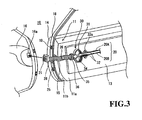
- Figs.3 to 11 show a system 10 for mounting a door harness 20.
- the door inner panel 11 has an internal face 11a facing the passenger compartment and a edge (side) face 11b facing the body panel 16 of a vehicle.
- a weather strip 18 is mounted so as to extend along a mounting line on edge face 11b.
- the door harness 20 is wired from the internal face 11 a of the door inner panel 11 to the body panel 16, along a path line that is closer to the compartment than is the mount line of the weather strip. In other words, among the weather strip 18 and the door harness 20, the door harness is the innermost.
- the internal face 11a of the door inner panel 11 is provided with a fitting portion, e.g. recessed portion 12.
- the comer portion formed by the internal face 11a and the edge face 11b is provided with a grooved (indented) portion 15.
- a weather strip 18 is mounted along a mount line traced on the edge face 11b of the door inner panel 11.
- the grooved portion 15 has a half-open base 15a that extends from the edge face of the door inner panel 11, parallel to the internal face thereof. This half-open base 15a is placed at the side of the passenger compartment, seen from the mount line of the weather strip 18.
- the door inner panel 11 is flanked from the outside of the vehicle by a metal door outer panel 14.
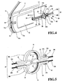
- the end portion of the door harness 20 is fitted with a grommet or duct or sheath 25 that comprises a bellows portion 26 e.g. in a cylindrical form.
- a first end portion of the grommet 25 is provided with a connector housing 28 containing a connector 21 (Fig.7B), whereas a second end portion of the grommet is provided with elastic means, e.g. a pair of expandable/compressible guide members 30 attached by fixing means e.g. a tie band 36.
- the grommet 25 is made of rubber or an elastomer.
- the connector housing 28 retains within its internal structure part of an inner frame 29 made of resin.
- the projecting part of the inner frame 29 is provided with e.g. a pair of protuberances 29a to engage with the car body.
- the pair of expandable/compressible guide members 30 (30A and 30B) is formed of a resin.
- Each guide member 30A comprises, at its central zone, elastic portions, e.g. spring portions 31, in the form of a semicircular arch.
- a grommet-fixing portion 35 having a flat shape extends from a first end of the elastic portions 31, and a panel-fixing portion 32 having a flat shape extends from a second end of the elastic portions 31.
- the panel-fixing portion 32 is further provided with a clipping portion 32a with a clip hole 32b (Figs. 8A, 8B).
- the expandable/compressible guide members 30 each comprise grooves 33 at their confronting internal faces and extending therealong. These grooves 33 define a C-shaped or U-shaped cross-section along the inside of which the door harness 20 is fitted.
- both ends of each of the elastic portions 31 are interconnected by a link member 34 e.g. in the form of X.
- the link member 34 connects: the confronting ends of the respective guide members 30A, 30B, for each of their ends, thereby forming top-bottom links, and the respective ends of each of the guide members, thereby forming longitudinal links (or left-right link in the figure).
- the door harness 20 is separated into two parts 20A and 20B, which are respectively held by the corresponding groove 33. As shown in Fig.7A, the two parts of door harness 20A and 20B are assembled into one section and led into the grommet 25.
- the grommet-fixing members 35 of the expandable/compressible guide members 30A and 30B are superposed on the second ends of the bellows portion 26 (e.g. in a cylindrical form) of the grommet 25, and fixed by the tie band 36.
- the grommet 25 is passed through the grooved portion 15 in the door inner panel 11 (Fig.3), and pulled toward the body panel 16.
- the resin protuberances 29a of the inner frame 29 are then inserted into the hole 16a of the body panel 16 and held therein, whilst the connector 21 at the first end of the grommet 25 is connected to another harness provided at the body side of the car.
- the door harness 20 and the second end of the pair of expandable/compressible guide members 30 are fixed to the compartment side of the mounting panel 13 by fitting a clip 40 through the clip hole 32b in the panel-fixing portion 32, into the mounting hole 13a in the mounting panel 13.
- the mounting panel 13 is then engaged with the door inner panel 11 through the fixing means 12 thereof.
- the compartment side of the resin panel 13 is mounted with trimming means, so as to cover the exposed portion of the door harness 20.
- the wiring path of the door harness 20 is located closer to the compartment side than is the weather strip 18.
- the door harness 20 is located closer to the compartment side than is the hinge arrangement 19 binding the door inner panel 11 to the body panel 16. Accordingly, when the door is opened or closed, the door harness is twisted or stretched or squashed.
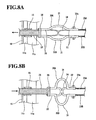
- the elastic portions 31 of the expandable/compressible guide members 30 are stretched together with the door harness 20, when the door is opened (see Fig.8A), whereas the elastic portions 31 are compressed and restored with the help of the link member 34, when the door is closed (see Fig.8B). Accordingly, the length of the door harness 20 exiting from the grooved portion 15 can be adjusted.
- the door harness 20 and the grommet 25 placed near the hinge arrangement 19 can follow smoothly the movement of the door, and the opening and shutting operations are facilitated. Further, since the door harness 20 is placed closer to the inside compartment than the weather strip 18 is, it is no longer necessary to flatten the door harness 20 and the grommet 25, or to specifically provide water-sealing means in order to secure high water sealability.
- the present invention is not limited to the embodiments disclosed above.
- the X-shaped linking member in the expandable/compressible guide members 30 is not necessarily required.
- the elastic portions in the form of a semicircular arch may be replaced by one or several curved flat plate(s). In that case, each of door harness halves 20A and 20B is arranged along the flat plates and held by tape.
- the expandable/compressible guide members may be fixed to the grommet, instead of the tie band, by any suitable linking member that does not deflect from the grommet when the above guide member is stretched or compressed.
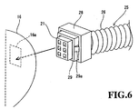
- the end portion of the door harness 20 is fitted with a grommet 25 and connected to a connector.
- the grommet 25 is made of rubber or an elastomer and integrates an elastic portion as in the first embodiment.
- the elastic portion comprises, going from the door side to the car's body side: a comparatively long looped section 41 having a cylindrical shape through which the door harness is passed, a comparatively short spring member 27 which binds both ends of the looped section 41 by forming a straight-line path between the ends, so maintaining the loop configuration, a bellows portion 26 e.g. having cylindrical shape, and a connector housing 28.
- the looping part 41a defined by the spring member 27 is passed through by the excess length portion 20a of the door harness such that the door harness 20 can expand or contract.
- the spring member 27 is in the form of a band having a rectangular cross-section, and is highly expandable and compressible. Further, as shown in Fig.6, an inner frame 29 e.g. made of resin is provided so as to project partly from the connector housing 28. This projecting portion comprises e.g. a pair of protuberances 29a with which the body panel is engaged.
- end portion of the looped section 41 that is distal from the connector housing 28, where the spring member 27 is engaged integrates a panel fixing portion 32 with a clip-fastening hole 32b.
- the mounting panel 13 is also provided with mounting hole 13a (Fig.10).
- the door harness 20 mounted with the grommet 25 passed on the internal face 11a of the door inner panel 11 and pulled out toward the body panel 16, such that the bellows portion 26 of the grommet 25 is installed in the grooved portion 15.
- the connector 21 of the pulled-out door harness 20 is then connected to a harness in the body panel 16 through a hole 16a formed therein, such that the protuberances 29a of the inner frame 29 mounted with the grommet 25 is engaged with the hole 16a.
- the end portion of the grommet 25 distal from the connector housing 28, together with the door harness 20, are bound to the surface of the mounting panel 13 facing the compartment of the vehicle, by inserting a clip 40 into the mounting hole 13a of the mounting panel 13 and the clip-fastening hole 32b in the panel-fixing portion 32 of the grommet 25 (Figs.9 and 10).
- the mounting panel 13 is then fitted into the recessed portion 12 in the door inner panel 11.
- the exposed portion of the door harness 20 is covered with a trim.
- the wiring path of the door harness 20 is located, compared to weather strip 18, closer to the passenger compartment.
- the door harness 20 is located more closely to the compartment, compared to the hinge arrangement 19 binding the door inner panel 11 to the body panel 16. Accordingly, when the door is opened or closed, the door harness is twisted, stretched or compressed. However, the spring portion 27 of the grommet 25 is stretched together with the door harness 20, when the door is opened (see Fig.12A), and conversely the spring portion 27 is shrunk and restored, when the door is closed (see Fig.12B). In this way, the length of the door harness 20 exiting from the grooved portion 15 can be regulated.
- the door harness 20 and the grommet 25 placed near the hinge arrangement 19 can follow smoothly the movement of the door, and the opening and shutting operations are improved. Further, since the door harness 20 is placed closer to the inside compartment than the weather strip 18 is, it is no longer necessary to flatten the door harness 20 and the grommet 25, or to specifically provide water-sealing means in order to secure high water sealability.
- the spring portion can be means other than the band having a rectangular cross-section.
- the means are expandable and contractable, they may be a tube or a round cable.
- the grommet (duct or sheath) 25 may be formed of an elastomer. Further, the panel-fixing portion 32 of the grommet 25 may be configured so that it can be fixed to the internal base of the recessed portion 12 of the door inner panel 11.
Landscapes
- Engineering & Computer Science (AREA)
- Mechanical Engineering (AREA)
- Installation Of Indoor Wiring (AREA)
Applications Claiming Priority (4)
| Application Number | Priority Date | Filing Date | Title |
|---|---|---|---|
| JP2003419113 | 2003-12-17 | ||
| JP2003419113A JP2005178456A (ja) | 2003-12-17 | 2003-12-17 | ドアハーネスの取付構造 |
| JP2003419473A JP2005178466A (ja) | 2003-12-17 | 2003-12-17 | ドアハーネスの取付構造 |
| JP2003419473 | 2003-12-17 |
Publications (2)
| Publication Number | Publication Date |
|---|---|
| EP1544046A1 true EP1544046A1 (fr) | 2005-06-22 |
| EP1544046B1 EP1544046B1 (fr) | 2007-02-28 |
Family
ID=34525522
Family Applications (1)
| Application Number | Title | Priority Date | Filing Date |
|---|---|---|---|
| EP04293006A Expired - Lifetime EP1544046B1 (fr) | 2003-12-17 | 2004-12-15 | Structure pour installer un faiseau de câbles de portières |
Country Status (3)
| Country | Link |
|---|---|
| US (1) | US7053304B2 (fr) |
| EP (1) | EP1544046B1 (fr) |
| DE (1) | DE602004004986T2 (fr) |
Cited By (4)
| Publication number | Priority date | Publication date | Assignee | Title |
|---|---|---|---|---|
| EP1681206A1 (fr) * | 2005-01-18 | 2006-07-19 | Volkswagen Aktiengesellschaft | Dispositif incluant un manchon d'étanchéité pour le passage entre des parties de véhicules, mobiles l'une par rapport à l'autre |
| EP2253512A1 (fr) * | 2009-05-22 | 2010-11-24 | Yazaki Corporation | Sous-unité de faisceau de câbles, unité de faisceau de câbles et procédé pour assembler l'unité de faisceau de câbles |
| EP2218612A4 (fr) * | 2007-12-12 | 2011-01-19 | Sumitomo Wiring Systems | Structure d'acheminement pour faisceau de câbles de portière |
| WO2012091175A1 (fr) * | 2010-12-28 | 2012-07-05 | Yazaki Corporation | Faisceau de câbles |
Families Citing this family (26)
| Publication number | Priority date | Publication date | Assignee | Title |
|---|---|---|---|---|
| JP4406374B2 (ja) * | 2005-01-07 | 2010-01-27 | 矢崎総業株式会社 | グロメット組立体の組付構造 |
| DE102005043177A1 (de) * | 2005-09-09 | 2007-03-29 | Johnson Controls Interiors Gmbh & Co. Kg | Innerverkleidung einer Kraftfahrzeugtür mit Kabelübergang |
| US7244894B1 (en) * | 2005-09-28 | 2007-07-17 | Yazaki North America, Inc. | Grommet for a vehicle door assembly |
| JP4306692B2 (ja) | 2006-05-15 | 2009-08-05 | 住友電装株式会社 | ワイヤハーネス分岐部へのプロテクタの外装方法およびワイヤハーネスの分岐構造 |
| JP4758850B2 (ja) * | 2006-08-14 | 2011-08-31 | 矢崎総業株式会社 | リンクへのワイヤハーネスの配索構造 |
| US7533920B2 (en) * | 2006-10-26 | 2009-05-19 | Nissan Technical Center North America, Inc. | Selectively detachable tailgate hinge assembly |
| US7615713B2 (en) * | 2006-12-05 | 2009-11-10 | Delphi Technologies, Inc. | Mounting structure for wiring harness |
| JP2008143235A (ja) * | 2006-12-06 | 2008-06-26 | Sumitomo Wiring Syst Ltd | ドア用ワイヤハーネスの配索構造 |
| US8020920B2 (en) * | 2006-12-06 | 2011-09-20 | Sumitomo Wiring Systems Ltd. | Outer protective assembly of wire harness for door and arranging structure of wire harness for door |
| JP5185536B2 (ja) * | 2007-01-17 | 2013-04-17 | 矢崎総業株式会社 | 給電装置 |
| US7749303B2 (en) * | 2007-08-30 | 2010-07-06 | The Boeing Company | Service life indicator for chemical filters |
| US7943854B1 (en) | 2008-09-19 | 2011-05-17 | Yazaki North America | Wire twist optimizing grommet |
| JP5517282B2 (ja) * | 2009-02-25 | 2014-06-11 | 矢崎総業株式会社 | ワイヤハーネスの配索構造 |
| CN102263345A (zh) * | 2010-05-24 | 2011-11-30 | 鸿富锦精密工业(深圳)有限公司 | 连接件 |
| JP5634772B2 (ja) * | 2010-07-05 | 2014-12-03 | 矢崎総業株式会社 | ワイヤハーネス配索体及びワイヤハーネス配索ユニット |
| JP5747694B2 (ja) * | 2011-07-06 | 2015-07-15 | 住友電装株式会社 | グロメット |
| JP2013091461A (ja) * | 2011-10-27 | 2013-05-16 | Sumitomo Wiring Syst Ltd | ワイヤーハーネス配索構造部 |
| US8648259B2 (en) | 2012-01-12 | 2014-02-11 | Yazaki North America, Inc. | Accordion-style grommet with shape-influencing stiffeners |
| US9365170B2 (en) * | 2012-08-23 | 2016-06-14 | Yazaki North America, Inc. | Grommet assembly |
| JP6010820B2 (ja) * | 2012-11-21 | 2016-10-19 | 矢崎総業株式会社 | 電線用外装保護チューブ |
| DE102014111901B4 (de) * | 2014-08-20 | 2019-05-23 | Snaptrack, Inc. | Duplexer |
| WO2016153045A1 (fr) * | 2015-03-26 | 2016-09-29 | 古河電気工業株式会社 | Passe-fil et faisceau de fils à passe-fil |
| JP2017099205A (ja) * | 2015-11-27 | 2017-06-01 | 住友電装株式会社 | 電線外装材およびワイヤハーネス |
| US10913407B2 (en) | 2017-02-07 | 2021-02-09 | Ford Global Technologies, Llc | Grommet with tie-strap tower |
| US10414353B2 (en) | 2017-02-07 | 2019-09-17 | Ford Global Technologies, Llc | Grommet with tie-strap tower |
| JP7491062B2 (ja) * | 2020-06-03 | 2024-05-28 | 住友電装株式会社 | 配線部材 |
Citations (6)
| Publication number | Priority date | Publication date | Assignee | Title |
|---|---|---|---|---|
| US5556059A (en) * | 1993-06-28 | 1996-09-17 | Yazaki Corporation | Device for guiding wire harness of steering column |
| EP0855312A2 (fr) * | 1996-12-25 | 1998-07-29 | Sumitomo Wiring Systems, Ltd. | Arrangement de construction d'un faisceau de cables |
| US5884961A (en) * | 1997-02-06 | 1999-03-23 | Yazaki Corporation | Door wire harness arrangement structure for vehicles |
| US6092859A (en) * | 1998-03-18 | 2000-07-25 | Yazaki Corporation | Arrangement structure of door harness for vehicle |
| EP1236599A1 (fr) * | 2001-02-21 | 2002-09-04 | Sumitomo Wiring Systems, Ltd. | Système de montage d'un faisceau de cables pour portière |
| EP1241056A1 (fr) * | 2001-03-16 | 2002-09-18 | Yazaki Corporation | Dispositif pour retenir l'éxcédent de câble dans des portes coulissantes d'automobile |
Family Cites Families (5)
| Publication number | Priority date | Publication date | Assignee | Title |
|---|---|---|---|---|
| JPH10181479A (ja) | 1996-12-26 | 1998-07-07 | Sumitomo Wiring Syst Ltd | 自動車のドアヒンジ部におけるワイヤハーネス配索構造 |
| JP3467172B2 (ja) | 1997-06-27 | 2003-11-17 | 矢崎総業株式会社 | ワイヤハーネスの取付け構造 |
| JP3319425B2 (ja) | 1999-04-02 | 2002-09-03 | 住友電装株式会社 | ドア・ハーネスの配索構造および該配索構造に用いるグロメット |
| JP2001097141A (ja) * | 1999-09-29 | 2001-04-10 | Sumitomo Wiring Syst Ltd | 可動式ワイヤハーネス |
| JP3319454B2 (ja) | 1999-12-14 | 2002-09-03 | 住友電装株式会社 | ドア用グロメット |
-
2004
- 2004-12-15 EP EP04293006A patent/EP1544046B1/fr not_active Expired - Lifetime
- 2004-12-15 DE DE602004004986T patent/DE602004004986T2/de not_active Expired - Fee Related
- 2004-12-16 US US11/012,268 patent/US7053304B2/en not_active Expired - Fee Related
Patent Citations (6)
| Publication number | Priority date | Publication date | Assignee | Title |
|---|---|---|---|---|
| US5556059A (en) * | 1993-06-28 | 1996-09-17 | Yazaki Corporation | Device for guiding wire harness of steering column |
| EP0855312A2 (fr) * | 1996-12-25 | 1998-07-29 | Sumitomo Wiring Systems, Ltd. | Arrangement de construction d'un faisceau de cables |
| US5884961A (en) * | 1997-02-06 | 1999-03-23 | Yazaki Corporation | Door wire harness arrangement structure for vehicles |
| US6092859A (en) * | 1998-03-18 | 2000-07-25 | Yazaki Corporation | Arrangement structure of door harness for vehicle |
| EP1236599A1 (fr) * | 2001-02-21 | 2002-09-04 | Sumitomo Wiring Systems, Ltd. | Système de montage d'un faisceau de cables pour portière |
| EP1241056A1 (fr) * | 2001-03-16 | 2002-09-18 | Yazaki Corporation | Dispositif pour retenir l'éxcédent de câble dans des portes coulissantes d'automobile |
Cited By (6)
| Publication number | Priority date | Publication date | Assignee | Title |
|---|---|---|---|---|
| EP1681206A1 (fr) * | 2005-01-18 | 2006-07-19 | Volkswagen Aktiengesellschaft | Dispositif incluant un manchon d'étanchéité pour le passage entre des parties de véhicules, mobiles l'une par rapport à l'autre |
| US7408115B2 (en) | 2005-01-18 | 2008-08-05 | Volkswagen Ag | Device having a sealing grommet for leads to pass through between vehicles parts that can move in relation to one another |
| EP2218612A4 (fr) * | 2007-12-12 | 2011-01-19 | Sumitomo Wiring Systems | Structure d'acheminement pour faisceau de câbles de portière |
| EP2253512A1 (fr) * | 2009-05-22 | 2010-11-24 | Yazaki Corporation | Sous-unité de faisceau de câbles, unité de faisceau de câbles et procédé pour assembler l'unité de faisceau de câbles |
| US8487182B2 (en) | 2009-05-22 | 2013-07-16 | Yazaki Corporation | Wiring harness subunit, wiring harness unit and method for assembling wiring harness unit |
| WO2012091175A1 (fr) * | 2010-12-28 | 2012-07-05 | Yazaki Corporation | Faisceau de câbles |
Also Published As
| Publication number | Publication date |
|---|---|
| US20050148212A1 (en) | 2005-07-07 |
| EP1544046B1 (fr) | 2007-02-28 |
| US7053304B2 (en) | 2006-05-30 |
| DE602004004986T2 (de) | 2007-11-08 |
| DE602004004986D1 (de) | 2007-04-12 |
Similar Documents
| Publication | Publication Date | Title |
|---|---|---|
| EP1544046A1 (fr) | Structure pour installer un faiseau de câbles de portières | |
| JP3570317B2 (ja) | 自動車用スライドドアのワイヤハーネス配索構造 | |
| US6515229B2 (en) | Structure of installing wire harness for sliding door | |
| US8182022B2 (en) | Power supply apparatus for sliding door | |
| EP2644456A1 (fr) | Structure de cheminement de câblage pour faisceau électrique, et élément protecteur | |
| EP2579406A2 (fr) | Structure d'installation de faisceau de câble et bande aplatie de faisceau de câble | |
| US7202415B2 (en) | Wire harness construction | |
| JP4746965B2 (ja) | スライド構造体用の給電装置 | |
| US7053305B2 (en) | Structure for mounting a door wire harness | |
| KR20100072073A (ko) | 도어용 와이어 하네스의 배치 구조 | |
| US7375281B2 (en) | Power-supplying apparatus for sliding structure | |
| US6481547B2 (en) | Apparatus for taking up slack of wire harness | |
| EP0812734B1 (fr) | Un arrangement d'un faisceau de câbles de véhicule automobile | |
| CN100442616C (zh) | 线束导向保护器、电线过长部分收取结构和前者固定方法 | |
| KR101029276B1 (ko) | 차량의 차체와 도어 사이로 케이블을 통과시키기 위한 시스템 및 그 시스템을 구비하는 차량 | |
| JP3260060B2 (ja) | 可動式ワイヤハーネス | |
| US5792995A (en) | Wire harness grommet with tubular section and fastener | |
| JP4412150B2 (ja) | グロメットを用いたワイヤハーネスの配索構造 | |
| US7294784B2 (en) | Electric supply apparatus | |
| JP2005178466A (ja) | ドアハーネスの取付構造 | |
| JP2005178456A (ja) | ドアハーネスの取付構造 | |
| US20230271576A1 (en) | Door component, grommet, and wiring module | |
| JP2009254218A (ja) | 可撓性チューブ及びそれを備えたスライドドアのハーネス配設構造 | |
| JPH1016670A (ja) | 自動車のドアヒンジ部におけるワイヤハーネス配索構造 | |
| KR960005866B1 (ko) | 자동차의 하니스 홀더 |
Legal Events
| Date | Code | Title | Description |
|---|---|---|---|
| PUAI | Public reference made under article 153(3) epc to a published international application that has entered the european phase |
Free format text: ORIGINAL CODE: 0009012 |
|
| AK | Designated contracting states |
Kind code of ref document: A1 Designated state(s): AT BE BG CH CY CZ DE DK EE ES FI FR GB GR HU IE IS IT LI LT LU MC NL PL PT RO SE SI SK TR |
|
| AX | Request for extension of the european patent |
Extension state: AL BA HR LV MK YU |
|
| 17P | Request for examination filed |
Effective date: 20051222 |
|
| AKX | Designation fees paid |
Designated state(s): DE FR GB IT |
|
| GRAP | Despatch of communication of intention to grant a patent |
Free format text: ORIGINAL CODE: EPIDOSNIGR1 |
|
| GRAS | Grant fee paid |
Free format text: ORIGINAL CODE: EPIDOSNIGR3 |
|
| GRAA | (expected) grant |
Free format text: ORIGINAL CODE: 0009210 |
|
| AK | Designated contracting states |
Kind code of ref document: B1 Designated state(s): DE FR GB IT |
|
| REG | Reference to a national code |
Ref country code: GB Ref legal event code: FG4D |
|
| REF | Corresponds to: |
Ref document number: 602004004986 Country of ref document: DE Date of ref document: 20070412 Kind code of ref document: P |
|
| ET | Fr: translation filed | ||
| PLBE | No opposition filed within time limit |
Free format text: ORIGINAL CODE: 0009261 |
|
| STAA | Information on the status of an ep patent application or granted ep patent |
Free format text: STATUS: NO OPPOSITION FILED WITHIN TIME LIMIT |
|
| 26N | No opposition filed |
Effective date: 20071129 |
|
| PG25 | Lapsed in a contracting state [announced via postgrant information from national office to epo] |
Ref country code: IT Free format text: LAPSE BECAUSE OF FAILURE TO SUBMIT A TRANSLATION OF THE DESCRIPTION OR TO PAY THE FEE WITHIN THE PRESCRIBED TIME-LIMIT Effective date: 20070228 |
|
| PG25 | Lapsed in a contracting state [announced via postgrant information from national office to epo] |
Ref country code: DE Free format text: LAPSE BECAUSE OF NON-PAYMENT OF DUE FEES Effective date: 20080701 |
|
| REG | Reference to a national code |
Ref country code: FR Ref legal event code: ST Effective date: 20081020 |
|
| PG25 | Lapsed in a contracting state [announced via postgrant information from national office to epo] |
Ref country code: FR Free format text: LAPSE BECAUSE OF NON-PAYMENT OF DUE FEES Effective date: 20071231 |
|
| GBPC | Gb: european patent ceased through non-payment of renewal fee |
Effective date: 20081215 |
|
| PG25 | Lapsed in a contracting state [announced via postgrant information from national office to epo] |
Ref country code: GB Free format text: LAPSE BECAUSE OF NON-PAYMENT OF DUE FEES Effective date: 20081215 |