EP1544687B1 - Appareil et méthode de formation d'images capable de transfert d'image efficace (electrographie en couleur) - Google Patents
Appareil et méthode de formation d'images capable de transfert d'image efficace (electrographie en couleur) Download PDFInfo
- Publication number
- EP1544687B1 EP1544687B1 EP04029208.8A EP04029208A EP1544687B1 EP 1544687 B1 EP1544687 B1 EP 1544687B1 EP 04029208 A EP04029208 A EP 04029208A EP 1544687 B1 EP1544687 B1 EP 1544687B1
- Authority
- EP
- European Patent Office
- Prior art keywords
- toner image
- image
- transport mechanism
- scale
- recording medium
- Prior art date
- Legal status (The legal status is an assumption and is not a legal conclusion. Google has not performed a legal analysis and makes no representation as to the accuracy of the status listed.)
- Expired - Lifetime
Links
- 238000000034 method Methods 0.000 title claims description 11
- 230000007246 mechanism Effects 0.000 claims description 27
- 239000010410 layer Substances 0.000 claims description 18
- 230000007723 transport mechanism Effects 0.000 claims description 16
- 239000011347 resin Substances 0.000 claims description 13
- 229920005989 resin Polymers 0.000 claims description 13
- 239000012790 adhesive layer Substances 0.000 claims description 8
- 239000002131 composite material Substances 0.000 description 10
- 239000011521 glass Substances 0.000 description 7
- 239000003086 colorant Substances 0.000 description 6
- 238000007599 discharging Methods 0.000 description 6
- 238000000926 separation method Methods 0.000 description 6
- 230000008901 benefit Effects 0.000 description 4
- 229920001971 elastomer Polymers 0.000 description 4
- 238000004140 cleaning Methods 0.000 description 3
- 238000001514 detection method Methods 0.000 description 3
- 239000000463 material Substances 0.000 description 3
- YCKRFDGAMUMZLT-UHFFFAOYSA-N Fluorine atom Chemical compound [F] YCKRFDGAMUMZLT-UHFFFAOYSA-N 0.000 description 2
- 239000000853 adhesive Substances 0.000 description 2
- 230000001070 adhesive effect Effects 0.000 description 2
- 229910052731 fluorine Inorganic materials 0.000 description 2
- 239000011737 fluorine Substances 0.000 description 2
- 239000002184 metal Substances 0.000 description 2
- 230000001105 regulatory effect Effects 0.000 description 2
- 238000005299 abrasion Methods 0.000 description 1
- 230000015572 biosynthetic process Effects 0.000 description 1
- 239000003575 carbonaceous material Substances 0.000 description 1
- 239000011248 coating agent Substances 0.000 description 1
- 238000000576 coating method Methods 0.000 description 1
- 239000004020 conductor Substances 0.000 description 1
- 229920001577 copolymer Polymers 0.000 description 1
- 230000001419 dependent effect Effects 0.000 description 1
- 230000006866 deterioration Effects 0.000 description 1
- 239000000428 dust Substances 0.000 description 1
- 238000005530 etching Methods 0.000 description 1
- 229920001973 fluoroelastomer Polymers 0.000 description 1
- 238000003780 insertion Methods 0.000 description 1
- 230000037431 insertion Effects 0.000 description 1
- 238000012986 modification Methods 0.000 description 1
- 230000004048 modification Effects 0.000 description 1
- 230000003287 optical effect Effects 0.000 description 1
- 230000002093 peripheral effect Effects 0.000 description 1
- 230000008569 process Effects 0.000 description 1
- 230000004044 response Effects 0.000 description 1
- 230000032258 transport Effects 0.000 description 1
Images


Classifications
-
- G—PHYSICS
- G03—PHOTOGRAPHY; CINEMATOGRAPHY; ANALOGOUS TECHNIQUES USING WAVES OTHER THAN OPTICAL WAVES; ELECTROGRAPHY; HOLOGRAPHY
- G03G—ELECTROGRAPHY; ELECTROPHOTOGRAPHY; MAGNETOGRAPHY
- G03G15/00—Apparatus for electrographic processes using a charge pattern
- G03G15/01—Apparatus for electrographic processes using a charge pattern for producing multicoloured copies
-
- G—PHYSICS
- G03—PHOTOGRAPHY; CINEMATOGRAPHY; ANALOGOUS TECHNIQUES USING WAVES OTHER THAN OPTICAL WAVES; ELECTROGRAPHY; HOLOGRAPHY
- G03G—ELECTROGRAPHY; ELECTROPHOTOGRAPHY; MAGNETOGRAPHY
- G03G15/00—Apparatus for electrographic processes using a charge pattern
- G03G15/14—Apparatus for electrographic processes using a charge pattern for transferring a pattern to a second base
- G03G15/16—Apparatus for electrographic processes using a charge pattern for transferring a pattern to a second base of a toner pattern, e.g. a powder pattern, e.g. magnetic transfer
- G03G15/1665—Apparatus for electrographic processes using a charge pattern for transferring a pattern to a second base of a toner pattern, e.g. a powder pattern, e.g. magnetic transfer by introducing the second base in the nip formed by the recording member and at least one transfer member, e.g. in combination with bias or heat
- G03G15/167—Apparatus for electrographic processes using a charge pattern for transferring a pattern to a second base of a toner pattern, e.g. a powder pattern, e.g. magnetic transfer by introducing the second base in the nip formed by the recording member and at least one transfer member, e.g. in combination with bias or heat at least one of the recording member or the transfer member being rotatable during the transfer
- G03G15/1685—Structure, details of the transfer member, e.g. chemical composition
-
- G—PHYSICS
- G03—PHOTOGRAPHY; CINEMATOGRAPHY; ANALOGOUS TECHNIQUES USING WAVES OTHER THAN OPTICAL WAVES; ELECTROGRAPHY; HOLOGRAPHY
- G03G—ELECTROGRAPHY; ELECTROPHOTOGRAPHY; MAGNETOGRAPHY
- G03G2215/00—Apparatus for electrophotographic processes
- G03G2215/16—Transferring device, details
- G03G2215/1604—Main transfer electrode
- G03G2215/1623—Transfer belt
Definitions
- the present invention relates to a method and apparatus for electrophotographic image forming.
- the present invention relates to a method and apparatus for electrophotographic image forming capable of effectively performing an image transfer operation.
- the color electrophotographic image forming apparatuses can generally be classified into two types, that is, a one drum image forming apparatus and a tandem image forming apparatus.
- the one drum image forming apparatus includes a photoconductive element having a plurality of image developing units around the photoconductive element. These image developing units electrically hold respective toners of different colors to sequentially form each of respective toner images on a surface of the photoconductive element. These respective toner images are overlaid onto a recording sheet so that a full-color image is formed.
- the tandem image forming apparatus includes a plurality of photoconductive elements and a plurality of developing units corresponding to the plurality of respective photoconductive elements.
- the plurality of developing units develop respective color toner images of different colors on the plurality of respective photoconductive elements. These color toner images are sequentially transferred on a recording sheet to form a full-color image.
- the one drum image forming apparatus has an advantage such that one photoconductive element makes a device relatively compact and inexpensive.
- one drum image forming apparatus having the one photoconductive element needs to repeat its image forming operation for several times (generally four times) to develop a full-color image. This process consumes a considerable amount of time.
- the tandem image forming apparatus has an advantage such that a plurality of photoconductive elements can reduce a time period of image forming operation.
- the plurality of photoconductive elements make an image forming apparatus larger and expensive.
- tandem image forming apparatus Since the market requires a full-color image forming apparatus performs its image forming operations at a speed equivalent to a monochrome image forming apparatus, the tandem image forming apparatus is attracting attention.
- a tandem image forming apparatus includes a direct transfer system and an indirect transfer system.
- a plurality of photoconductive elements are arranged in parallel with a surface of a sheet transfer belt that forms an endless belt, and a plurality of transfer units having respective colors of yellow (y), magenta (m), cyan (c) and black (bk) are disposed in a vicinity of the plurality of respective photoconductive elements. Respective color toner images formed on surfaces of the plurality of photoconductive elements are sequentially transferred by the plurality of transfer units onto a recording sheet that is conveyed by the sheet transfer belt.
- a plurality of photoconductive elements are arranged in parallel with a surface of an intermediate transfer member forming an endless belt. Respective color toner images formed on surfaces of the plurality of photoconductive elements are sequentially transferred and overlaid by a plurality of respective primary transfer units onto a surface of the intermediate transfer member so that an overlaid color toner image is formed. Subsequently, a secondary transfer unit transfers the overlaid color toner image onto a recording sheet.
- the secondary transfer unit may employ a transfer belt system or a roller system.
- the linear encoder performs a feedback control based on its output and uses the output to adjust the rate for writing. This system may efficiently be used to achieve accurate alignment.
- the endless belt has a surface that is clear and transparent
- encoder marks may be printed on the clear surface of the endless belt so that the linear encoder can read the encoder marks to measure a surface speed of the endless belt.
- the endless belt should include conductive materials such as carbon material, which prevents the surface of the endless belt from being clear and transparent.
- a reflective linear encoder may be provided on the endless belt.
- the reflective linear encoder generally includes a metal etching or printing layer to obtain high reflectance.
- the reflective linear encoder should be carefully positioned when it is disposed in a vicinity of a transfer unit that includes components having electrically high voltage such as a bias roller. When a creepage distance between the reflective linear encoder and the transfer unit is not sufficiently maintained, high voltage may leak from the transfer unit to the metal layer of the linear encoder, causing electromagnetic noises and deterioration in image quality.
- the above-described problems may occur in a tandem image forming apparatus and an one drum image forming apparatus, and should be solved to obtain images having higher quality.
- JP 11024507 shows a color copying machine with an endless transfer belt which is stretched over supporting rollers and a scale for detecting the moving amount of the belt which is formed at the inner peripheral surface of the transfer belt.
- a driving mode of a driving transfer belt is controlled based on the detection result of a detector for reading the scale.
- JP 2001016883 shows a turning surface of a transfer belt which is formed with a plurality of reference marks with respect to the running direction.
- the number of reference marks detected by mark detection sensor is specified from the number of the reference marks counted by a mark detection sensor and the stored data is referred to by the number of the specified mark.
- the turning position on the turning surface at the time when the specified reference mark is detected can be specified so as to control the rotating speed of the motor. This is essentially equal to a feed-forward control.
- the present invention has been made in view of the above-described circumstances.
- An object of the present invention is to provide an apparatus according to claims 1 and 8.
- Another object of the present invention is to provide a belt transfer unit included in the above-described image transferring device and capable of performing a feedback control to maintain constant reading accuracy and prevent a voltage leak of a transfer mechanism.
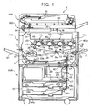
- FIG. 1 a structure of a tandem-type color image forming apparatus 1 according to an exemplary embodiment of the present invention is now described.
- the tandem-type color image forming apparatus 1 of FIG. 1 employs an indirect transfer system, and includes a color copying engine 100, a sheet feeding table 200, an image scanner 300 and an automatic document feeder (ADF) 400.
- ADF automatic document feeder
- the color copying engine 100 is disposed on the sheet feeding table 200.
- the image scanner 300 is provided on the upper surface of the color copying engine 100.
- the automatic document feeder 400 is provided on the top of the image scanner 300.
- the color copying engine 100 can include four image forming units 18y, 18c, 18m and 18bk as a tandem-type image forming mechanism 20, an intermediate transfer member 10 as a transfer mechanism, a writing unit 21 as a writing mechanism, a fixing unit 25 as an fixing mechanism, and a portion of a sheet feeding mechanism that is mainly disposed in the sheet feeding table 200.
- the four image forming units 18y, 18c, 18m and 18bk of the tandem-type image forming mechanism 20 include four photoconductive elements 40y, 40c, 40m and 40bk, respectively.
- the four photoconductive elements 40y, 40c, 40m and 40bk can have similar structures and functions, except that the toners are different colors to form magenta images, cyan images, yellow images and black images, respectively.
- the four image forming units 18y, 18c, 18m and 18bk are separately arranged at positions having horizontal heights or elevations forming the tandem-type image forming mechanism 20.
- the photoconductive elements 40y, 40c, 40m and 40bk separately receive respective light laser beams emitted by the writing unit 21, such that electrostatic latent images are formed on the surfaces of the four photoconductive elements 40y, 40c, 40m and 40bk.
- Respective charging rollers (not shown) are held in contact with the photoconductive elements 40y, 40c, 40m and 40bk to charge respective surfaces of the photoconductive elements 40y, 40c, 40m and 40bk.
- Respective developing units are separately disposed in a vicinity of or adjacent the four image forming units 18y, 18c, 18m and 18bk, respectively.
- the respective developing units store the different colored toners for the image forming units 18y, 18c, 18m and 18bk.
- the writing unit 21 is provided at a position above the tandem-type image forming mechanism 20.
- the transfer mechanism including the intermediate transfer belt 10 is located or disposed below the tandem-type image forming mechanism 20 (substantially at the center of the tandem-type color image forming apparatus 1).
- the intermediate transfer member 10 forms an endless belt and is passed over or surrounds a plurality of supporting rollers 14, 15 and 16.
- the intermediate transfer member 10 is held in contact with the photoconductive elements 40y, 40c, 40m and 40bk, and is driven to rotate clockwise as indicated by an arrow as shown in FIG. 1 .
- the intermediate transfer member 10 forms a base layer that is coated with an inextensible fluorine resin or an extensible rubber applied to an inextensible material such as a canvas.
- an elastic layer Provided on the base layer is an elastic layer.
- the elastic layer is made of, for example, a fluororubber or acrylonitrile-butadiene copolymer rubber.
- the surface of the elastic layer is covered with a smooth coat layer by coating a fluorine resin, for example.
- an intermediate transfer member cleaning unit 17 is provided in the left side of the supporting roller 15.
- the intermediate transfer member cleaning unit 17 removes a residual toner on the intermediate transfer member 10 after image formation.
- Four primary transfer units 19y, 19c, 19m and 19bk are disposed inside a loop of the intermediate transfer member 10 to face the respective photoconductive elements 40y, 40c, 40m and 40bk, which are accommodated in the image forming units 18y, 18c, 18m and 18bk.
- a secondary transfer unit 22 is located on the opposite side of the intermediate transfer member 10 from the tandem type image forming mechanism 20.
- the secondary transfer unit 22 includes a secondary transfer belt 24 that is an endless belt, and the transfer belt 24 is extended between two secondary transfer rollers 23a and 23b.
- the secondary transfer unit 22 is arranged such that a portion of the secondary transfer belt 24 close to the secondary transfer roller 23a presses the intermediate transfer member 10 against the supporting roller 16.
- an overlaid color toner image formed on the surface of the intermediate transfer member 10 is transferred onto the recording sheet.
- the fixing unit 25 is positioned at a lower left side of the color copying engine 100, in a vicinity of the secondary transfer roller 23b and below the supporting roller 15.
- the fixing unit 25 includes a fixing belt 26 and a pressure roller 27 and is configured to press a pressure roller 27 against a fixing belt 26 that is an endless belt.
- the secondary transfer unit 22 also serves as a sheet transport mechanism for transporting a recording sheet having a color toner image thereon to the fixing unit 25.
- a transfer roller or a non-contact transfer charging unit may be used as an alternative to the secondary transfer unit 22. With such a belt transport mechanism, it may be difficult to achieve a mechanism for transporting a recording sheet having a color toner image thereon to the fixing unit 25.
- the color copying engine 100 is further provided with a sheet reverse unit 28 for reversing a recording sheet on one side of which an image is formed so that another image can be formed on the other side of the recording sheet for a duplex image forming operation in a duplex copy mode.
- the sheet reverse unit 28 is arranged under the secondary transfer unit 22 and the fixing unit 25 in substantially parallel to the image forming mechanism 20.
- the color copying engine 100 includes several components, such as a sheet transporting passage 48 and a pair of registration rollers 49 serving as the sheet feeding mechanism, which will be described below, the sheet feeding mechanism is mainly arranged in the sheet feeding table 200.
- the sheet feeding table 200 serving as the sheet feeding mechanism is arranged in a lower portion of the tandem-type color image forming apparatus 1, and includes sheet feeding rollers 42a, 42b and 42c, a sheet bank 43, sheet feeding cassettes 44a, 44b and 44c, sheet separation rollers 45a, 45b and 45c, a sheet transporting passage 46 and a plurality of sheet feeding rollers 47.
- the sheet feeding cassettes 44a, 44b and 44c are provided to the sheet bank 43 and are loaded with a stack of sheets of particular size including a recording sheet S (shown in FIG. 2 ).
- the recording sheet is fed from one of the sheet feeding cassettes 44a, 44b and 44c and is conveyed toward the pair of registration rollers 49.
- the sheet feeding mechanism also includes a manual sheet feeding tray 51, a switch pawl 55, a pair of sheet discharging rollers 56 and a sheet discharging tray 57.
- the manual sheet feeding tray 51 is mounted on the right side of the color copying engine 100 of FIG. 1 , and includes sheet discharging rollers 50, sheet separation rollers 52 and a manual sheet transporting passage 53. After opening the manual sheet feeding tray 51, an operator of the tandem-type color image forming apparatus 1 may feed sheets by hand.
- the image scanner 300 includes an original document stacker 30 and a contact glass 32.
- the ADF 400 includes first and second moving units 33 and 34, an image forming lens 35 and an image reading sensor 36.
- a set of original documents are placed in a face-up orientation on the original document stacker 30 of the ADF 400.
- the set of original documents can manually be placed sheet by sheet directly on the contact glass 32 of the image scanner 300.
- an operator lifts up the ADF 400 having a shell-like openable structure.
- the operator lowers the ADF 400 to a closing position, thereby an entire surface of the original document placed on the contact glass 32 may be pressed by a lower surface of the ADF 400.
- a start button (not shown) is pressed, an uppermost sheet of the set of original documents placed on the ADF 400 is separated and is transported to the contact glass 32 of the image scanner 300 and, subsequently, the image scanner 300 is activated. That is, the first and second moving units 33 and 34 of the image scanner 300 slide in a predetermined direction.
- the image scanner 300 is immediately activated upon the press of the start button.
- the first moving unit 33 including a light source and a mirror (both not shown) causes a light beam to emit and deflects the light beam reflected by the original document placed on the contact glass 32.
- the second moving unit 34 including mirrors (not shown) receives the light beam reflected by the mirror or the first moving unit 33 and reflects the light beam to the image reading sensor 36 via the image forming lens 35.
- one of the supporting rollers 14, 15 and 16 is driven by a drive motor (not shown) to rotate the other two rollers, thereby causing the intermediate transfer member 10 to rotate.
- the image forming units 18y, 18c, 18m and 18bk are driven to rotate the corresponding photoconductive elements 40y, 40c, 40m and 40bk to form single color images in yellow, cyan, magenta and black on the respective photoconductive elements 40y, 40c, 40m and 40bk in the image forming mechanism 20.
- each of the photoconductive elements 40y, 40c, 40m and 40bk rotates in a clockwise direction in FIG. 1 and is uniformly charged with the corresponding charging rollers (not shown).
- the writing unit 21 emits the light beams corresponding to the respective color image data and irradiates the photoconductive elements 40y, 40c, 40m and 40bk of the image forming units 18y, 18c, 18m and 18bk, respectively.
- Electrostatic latent images corresponding to the respective color image data are formed on respective surfaces of the photoconductive element 40y, 40c, 40m and 40bk.
- the electrostatic latent images formed on the respective photoconductive elements 40y, 40c, 40m and 40bk are visualized by the respective developing units (not shown) containing respective color toners therein, into yellow, cyan, magenta and black toner images, respectively.
- Those color toner images are sequentially overlaid on the surface of the intermediate transfer member 10 such that a composite color image is formed on the surface of the intermediate transfer member 10.
- the sheet feeding roller 42a is started to rotate so that the recording sheet S is conveyed to the sheet separation roller 45a in the sheet feeding cassette 44a provided to the sheet bank 43.
- the sheet separation roller 45a separates the recording sheet S from the following sheets and transfers the recording sheet S to the sheet transporting passage 46.
- the recording sheet S is conveyed by the plurality of sheet feeding rollers 47 through the sheet transporting passage 48 provided in the color copying engine 100, to the pair of registration rollers 49.
- the sheet feeding roller 50 is rotated to feed a set of recording sheets placed on the manual sheet feeding tray 51 to the pair of sheet separation rollers 52. Then, the pair of sheet separation rollers 52 separate an uppermost recording sheet from the set of recording sheets placed on the manual sheet feeding tray 51 and transfers the uppermost recording sheet, which will be referred to as the recording sheet S, to the pair of registration rollers 49 through the manual sheet transporting passage 53.
- the pair of registration rollers 49 stops and feeds the recording sheet S in synchronization with a movement of the composite color image towards a transfer area formed between the intermediate transfer member 10 and the secondary transfer unit 22.
- the transfer area is formed between a portion where the intermediate transfer member 10 is supported by the supporting roller 16 and a portion where the secondary transfer unit 22 is supported by the secondary transfer roller 23a.
- the composite color image formed on the surface of the intermediate transfer member 10 is transferred on the recording sheet S at the transfer area.
- the recording sheet S that has the composite color image thereon is further conveyed and passes the fixing unit 25.
- the fixing unit 25 fixes the composite color image to the recording sheet S by applying heat and pressure.
- the recording sheet S may be headed to the sheet reverse unit 28 when the switch pawl 55 selects a sheet transporting passage (not shown) for the duplex image forming operation.
- the sheet reverse unit 28 receives the recording sheet S on one side of which an image is formed and which is fed to the sheet reverse unit 28 after the recording sheet S is switched back in the face-down orientation at the sheet transporting passage of the sheet reverse unit 28.
- the sheet reverse unit 28 then transports the recording sheet S via the sheet transporting passage 48 to the pair of registration rollers 49 to pass through the transfer area formed between the intermediate transfer member 10 and the secondary image transfer unit 22 so that a next composite color image is transferred onto the back surface of the recording sheet S.
- the recording sheet S having composite color images printed on the front and back sides is conveyed to the fixing unit 25.
- the recording sheet S passes the fixing unit 25, the recording sheet S passes through a discharging passage selected by a switch pawl 55 and is discharged to a sheet discharging tray 57 via a pair of sheet discharging rollers 56.
- the intermediate transfer member cleaning unit 17 removes residual toners remaining on the surface of the intermediate transfer member 10 for a next image forming operation.
- the pair of registration rollers 49 are generally grounded, it may be biased to remove paper dust, for example, using a conductive rubber roller (e.g., a conductive NBR rubber).
- a conductive rubber roller e.g., a conductive NBR rubber
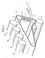
- the intermediate transfer member 10 includes a linear scale 70, a scale reading sensor 71 and a regulating member 73.
- the linear scale 70 is an optically readable scale provided in a vicinity of one end of the intermediate transfer member 10.
- the linear scale 70 is formed on an inner circumferential surface of the intermediate transfer member 10 over the entire circumference thereof.
- the scale reading sensor 71 is arranged at a portion between the supporting rollers 14 and 16, oppositely facing a surface of the linear scale 70.
- the regulating member 73 is provide on the one end of the inner surface of the intermediate transfer member 10 along the inner circumferential surface of the intermediate transfer member 10 to prevent a misalignment in a direction parallel to a rotating axis of each of the supporting rollers 14, 15 and 16.
- the linear scale 70 includes a film layer 70a and an adhesive layer 70b.
- the film layer 70a and the adhesive layer 70b include nonmetallic resin material and may be add with a color of white or yellow so that high reflectance can be obtained.
- the film layer 70a includes a plurality of pitch lines having deep color arranged on the adhesive layer 70b at predetermined intervals as shown in FIG. 3B , and is disposed facing the scale reading sensor 71 as shown in FIG. 3A .
- the scale reading sensor 71 detects light reflected by the plurality of pitch lines of the linear scale 70 to read optical signals.
- the scale 70 and the scale reading sensor 71 measure a linear velocity of the intermediate transfer member 10 to perform a feedback control to a drive source (not shown) of the supporting roller 14 of the intermediate transfer member 10, thereby driving the intermediate transfer member 10 with a high degree of positional accuracy.
- the film layer 70a and the adhesive layer 70b include nonmetallic material, and thereby are electrically isolated from the transfer unit that includes the bias roller having high voltage. That is, even if the bias roller is disposed in a vicinity of the linear scale 70, voltage of the bias roller may not leak to the linear scale 70, which may maintain electrical stability of the transfer unit.
- tandem-type color image forming apparatus 2 with a tandem-type direct transfer system is now described.
- tandem-type color image forming apparatus 2 having similar functions to those of components shown in FIG. 1 are given the same reference numerals.
- transfer units 81y, 81c, 81m and 81bk for the colors of yellow, cyan, magenta and black sequentially transfer images on respective photoconductive elements 40y, 40c, 40m and 40bk arranged horizontally to a recording sheet S that is conveyed by a sheet conveyance belt 80 in a form of endless belt as a rotatable member.
- the linear scale 70 and the scale reading sensor 71 are disposed under the sheet conveyance belt 80 for understanding both relationships clearly.
- the linear scale 70 and the scale reading sensor 71 are disposed as shown in FIGS. 3A and 3B . That is, the scale reading sensor 71 is provided in a range where the photoconductive elements 40y, 40c, 40m and 40bk and the sheet conveyance belt 80 are in contact.
- FIG. 5 a one-drum type color image forming apparatus 3 is described.
- components of the one-drum type color image forming apparatus 3 having similar functions to those of components shown in FIG. 1 are given the same reference numerals.
- the one-drum type color image forming apparatus 3 repeats four cycles of image forming operations to produce a full-color image.
- a drum-shaped photoconductive element 85 bears an electrostatic latent image of a single color on a surface thereof.
- the electrostatic latent image formed according to image data corresponding to the single color is developed as a toner image, and is transferred onto the intermediate transfer member 10 to form a composite color image.
- the composite color image on the intermediate transfer member 10 is transferred onto the recording sheet S (not shown) by the secondary transfer unit 22 to obtain a full-color image.
- the linear scale 70 and the scale reading sensor 71 are disposed between the supporting roller 16 and the photoconductive element 85 are in contact.
- the linear scale 700 includes a transparent film 700a and an adhesive layer 700b.
- the adhesive layer 700b includes a white or light colored adhesive and a deep colored adhesive, forming a plurality of pitch lines of deep color at predetermined intervals, which is similar to the linear scale 70 shown in FIG. 3B .
- the linear scale 700 of FIG. 6 With the structure of the linear scale 700 of FIG. 6 , the plurality of pitch lines on the linear scale 700 are entirely covered with the transparent film 700a, thereby the linear scale 700 may be isolated from voltage of a transfer unit having a bias roller and may be prevented from mechanical abrasion.
Landscapes
- Physics & Mathematics (AREA)
- General Physics & Mathematics (AREA)
- Electrostatic Charge, Transfer And Separation In Electrography (AREA)
- Color Electrophotography (AREA)
- Electrophotography Configuration And Component (AREA)
Claims (20)
- Appareil de formation et/ou de transfert d'image (1), comprenant :un mécanisme de transport (10) configuré pour transporter une image de toner ;une échelle (70, 700) prévue autour de tout un périmètre d'une surface du mécanisme de transport (10), l'échelle (70, 700) ayant au moins une couche de résine colorée ; etun mécanisme de lecture d'échelle (71) agencé en face de l'échelle (70, 700) et configuré pour lire l'échelle (70, 700),caractérisé en ce quela au moins une couche de résine colorée comprend une couche adhésive colorée (70b, 700b) et un film de résine transparente (70a, 700a) configuré pour isoler l'échelle (70, 700) d'une tension d'une unité de transfert.
- Appareil (1) selon la revendication 1, dans lequel la au moins une couche de résine colorée comprend un film de résine colorée.
- Appareil (1) selon l'une quelconque des revendications 1 à 2, comprenant en outre :au moins un élément de support d'image (40y, 40c, 40m, 40bk) configuré pour porter l'image de toner sur sa surface ; etun premier mécanisme de transfert configuré pour transférer l'image de toner du au moins un élément de support d'image (40y, 40c, 40m, 40bk) au mécanisme de transport.
- Appareil (1) selon la revendication 3, dans lequel le mécanisme de transport (10) comprend un élément de transfert intermédiaire agencé sous la forme d'une courroie sans fin et configuré pour recevoir l'image de toner du au moins un élément de support d'image (40y, 40c, 40m, 40bk).
- Appareil (1) selon la revendication 4, comprenant en outre :un second mécanisme de transfert (22) configuré pour transférer l'image de toner de l'élément de transfert intermédiaire sur un support d'enregistrement.
- Appareil (1) selon la revendication 3, dans lequel le mécanisme de transport comprend un élément de transport de support d'enregistrement (22) agencé sous la forme d'une courroie sans fin et configuré pour transporter un support d'enregistrement afin de recevoir directement l'image de toner du au moins un élément de support d'image (40y, 40c, 40m, 40bk).
- Appareil (1) selon l'une quelconque des revendications 1 à 6, comprenant en outre :un mécanisme d'écriture (21) configuré pour écrire optiquement une image latente électrostatique sur la surface du au moins un élément de support d'image (40y, 40c, 40m, 40bk) ; etun mécanisme de développement configuré pour développer l'image de toner basé sur l'image latente électrostatique.
- Procédé de formation d'image, comprenant les étapes consistant à :prévoir une échelle (70, 700) avec une pluralité de lignes de cercle primitif formées sur au moins une couche de résine colorée autour de tout un périmètre d'une surface d'un mécanisme de transport (10) ;faire tourner le mécanisme de transport (10) ;lire l'échelle (70, 700) selon la lumière reflétée par la pluralité de lignes de cercle primitif de l'échelle (70, 700) ; etcommander l'étape de rotation en fonction de l'information obtenue par l'étape de lecture,caractérisé en ce quel'étape de fourniture consistant à ce que la au moins une couche de résine colorée comprenne une couche adhésive colorée (70b, 700b) et un film de résine transparente (70a, 700b) pour isoler l'échelle (70, 700) d'une tension d'une unité de transfert.
- Procédé selon la revendication 8, dans lequel l'étape de fourniture comprend la au moins une couche de résine colorée comprenant un film de résine colorée.
- Procédé selon l'une des revendications 8 à 9, comprenant en outre les étapes consistant à :écrire optiquement une image latente électrostatique ;supporter l'image latente électrostatique ;développer une image de toner en fonction de l'image latente électrostatique ; ettransférer l'image de toner sur le mécanisme de transport (10).
- Procédé selon la revendication 10, dans lequel le mécanisme de transport (10) comprend un élément de transfert intermédiaire agencé sous la forme d'une courroie sans fin et configuré pour recevoir l'image de toner.
- Procédé selon la revendication 11, comprenant en outre l'étape consistant à :transférer l'image de toner de l'élément de transfert intermédiaire sur un support d'enregistrement.
- Procédé selon l'une des revendications 10 à 12, dans lequel le mécanisme de transport (10) comprend un élément de transport de support d'enregistrement (22) configuré pour transporter un support d'enregistrement afin de recevoir directement l'image de toner.
- Appareil (1) selon la revendication 1, comprenant en outre :un premier mécanisme de transfert configuré pour transférer l'image de toner du au moins un élément de support d'image (40y, 40c, 40m, 40bk) au mécanisme de transport (10).
- Appareil selon la revendication 14, dans lequel le mécanisme de transport (10) comprend un élément de transfert intermédiaire agencé sous la forme d'une courroie sans fin et configuré pour recevoir l'image de toner du au moins un élément de support d'image (40y, 40c, 40m, 40bk).
- Appareil (1) selon la revendication 17, comprenant en outre :un second mécanisme de transfert configuré pour transférer l'image de toner de l'élément de transfert intermédiaire sur un support d'enregistrement.
- Appareil (1) selon la revendication 1, dans lequel le mécanisme de transport (10) comprend un élément de transport de support d'enregistrement agencé sous la forme d'une courroie sans fin et configuré pour transporter un support d'enregistrement afin de recevoir directement l'image de toner du au moins un élément de support d'image (40y, 40c, 40m, 40bk).
- Appareil (1) selon la revendication 16, dans lequel les moyens de transport comprennent des moyens pour recevoir l'image de toner du au moins un élément de support d'image (40y, 40c, 40m, 40bk).
- Appareil selon la revendication 18, comprenant en outre :des seconds moyens pour transférer l'image de toner des moyens de réception sur un support d'enregistrement.
- Appareil selon la revendication 14, dans lequel les moyens de transport ou le mécanisme de transport comprennent des moyens pour transporter un support d'enregistrement afin de recevoir directement l'image de toner du au moins un élément de support d'image (40y, 40c, 40m, 40bk).
Applications Claiming Priority (2)
| Application Number | Priority Date | Filing Date | Title |
|---|---|---|---|
| JP2003416529A JP4350494B2 (ja) | 2003-12-15 | 2003-12-15 | 無端ベルト搬送装置および画像転写装置ならびにカラー画像形成装置 |
| JP2003416529 | 2003-12-15 |
Publications (2)
| Publication Number | Publication Date |
|---|---|
| EP1544687A1 EP1544687A1 (fr) | 2005-06-22 |
| EP1544687B1 true EP1544687B1 (fr) | 2013-06-19 |
Family
ID=34510585
Family Applications (1)
| Application Number | Title | Priority Date | Filing Date |
|---|---|---|---|
| EP04029208.8A Expired - Lifetime EP1544687B1 (fr) | 2003-12-15 | 2004-12-09 | Appareil et méthode de formation d'images capable de transfert d'image efficace (electrographie en couleur) |
Country Status (3)
| Country | Link |
|---|---|
| US (1) | US7684742B2 (fr) |
| EP (1) | EP1544687B1 (fr) |
| JP (1) | JP4350494B2 (fr) |
Families Citing this family (2)
| Publication number | Priority date | Publication date | Assignee | Title |
|---|---|---|---|---|
| JP2007024999A (ja) * | 2005-07-12 | 2007-02-01 | Fuji Xerox Co Ltd | 画像形成装置 |
| JP5553203B2 (ja) * | 2009-11-06 | 2014-07-16 | 株式会社リコー | ベルト駆動装置及びこれを用いた画像形成装置 |
Family Cites Families (25)
| Publication number | Priority date | Publication date | Assignee | Title |
|---|---|---|---|---|
| US3161521A (en) * | 1962-03-30 | 1964-12-15 | Technilith Inc | Method of making lithographic printing plates |
| JPH05134556A (ja) * | 1991-11-13 | 1993-05-28 | Sharp Corp | 画像形成装置 |
| JPH05323704A (ja) | 1992-05-21 | 1993-12-07 | Ricoh Co Ltd | 複写装置 |
| JPH10198179A (ja) * | 1996-12-28 | 1998-07-31 | Canon Inc | 転写装置及び画像形成装置 |
| JPH10232566A (ja) * | 1997-02-19 | 1998-09-02 | Canon Inc | 画像形成装置 |
| JPH1130892A (ja) * | 1997-05-13 | 1999-02-02 | Ricoh Co Ltd | カラー画像形成装置 |
| JPH1124507A (ja) | 1997-07-07 | 1999-01-29 | Ricoh Co Ltd | 画像形成装置 |
| JP2001016883A (ja) | 1999-06-29 | 2001-01-19 | Minolta Co Ltd | 回動体駆動装置、回動体駆動方法及び画像形成装置 |
| JP2001324880A (ja) * | 2000-05-15 | 2001-11-22 | Fuji Xerox Co Ltd | 中間転写体、及び画像形成装置 |
| JP2001201994A (ja) * | 2000-01-19 | 2001-07-27 | Ricoh Co Ltd | 画像形成装置 |
| JP2002108169A (ja) | 2000-07-26 | 2002-04-10 | Ricoh Co Ltd | 画像形成装置 |
| JP2002072607A (ja) | 2000-08-29 | 2002-03-12 | Ricoh Co Ltd | カラー画像形成装置 |
| JP2002072606A (ja) | 2000-08-29 | 2002-03-12 | Ricoh Co Ltd | カラー画像形成装置 |
| JP2002132009A (ja) | 2000-10-27 | 2002-05-09 | Ricoh Co Ltd | 画像形成装置 |
| JP2002244392A (ja) | 2001-02-16 | 2002-08-30 | Ricoh Co Ltd | 画像形成装置の駆動装置 |
| JP2002258574A (ja) | 2001-03-02 | 2002-09-11 | Ricoh Co Ltd | 画像形成装置、画像形成方法、画像形成方法をコンピュータに実行させるプログラム、およびそのプログラムを記録したコンピュータ読み取り可能な記録媒体 |
| JP2003057914A (ja) | 2001-08-09 | 2003-02-28 | Ricoh Co Ltd | 画像形成装置 |
| JP2003057910A (ja) | 2001-08-20 | 2003-02-28 | Ricoh Co Ltd | 画像形成装置 |
| JP3857101B2 (ja) | 2001-10-15 | 2006-12-13 | 株式会社リコー | 転写装置および画像形成装置 |
| JP2003128292A (ja) | 2001-10-30 | 2003-05-08 | Yuka Denshi Co Ltd | エンドレスベルトの位置検知マーク形成用テープ及び形成方法 |
| JP4294254B2 (ja) * | 2002-03-22 | 2009-07-08 | 株式会社リコー | 駆動制御装置及び画像形成装置 |
| JP2004061888A (ja) * | 2002-07-29 | 2004-02-26 | Ricoh Co Ltd | 画像形成装置 |
| JP2004109706A (ja) | 2002-09-19 | 2004-04-08 | Ricoh Co Ltd | ベルト駆動装置・転写駆動システム・画像形成装置 |
| JP2004198925A (ja) | 2002-12-20 | 2004-07-15 | Ricoh Co Ltd | 画像形成装置 |
| JP2004226867A (ja) | 2003-01-27 | 2004-08-12 | Ricoh Co Ltd | 画像転写装置 |
-
2003
- 2003-12-15 JP JP2003416529A patent/JP4350494B2/ja not_active Expired - Fee Related
-
2004
- 2004-12-09 EP EP04029208.8A patent/EP1544687B1/fr not_active Expired - Lifetime
- 2004-12-15 US US11/011,217 patent/US7684742B2/en not_active Expired - Lifetime
Also Published As
| Publication number | Publication date |
|---|---|
| JP2005173461A (ja) | 2005-06-30 |
| US7684742B2 (en) | 2010-03-23 |
| EP1544687A1 (fr) | 2005-06-22 |
| US20060008301A1 (en) | 2006-01-12 |
| JP4350494B2 (ja) | 2009-10-21 |
Similar Documents
| Publication | Publication Date | Title |
|---|---|---|
| US8139968B2 (en) | Image forming apparatus | |
| EP1387221B1 (fr) | Appareil de formation d'images avec un capteur de détection de la vitesse pour un élément rotatif | |
| US5394223A (en) | Apparatus for image registration | |
| US8798511B2 (en) | Image forming apparatus | |
| US8260179B2 (en) | Image forming apparatus including first and second image forming devices and first and second belt units | |
| US7657196B2 (en) | Compact image forming apparatus with a moveable optical sensor | |
| JP5790046B2 (ja) | 画像形成装置及び画像濃度制御方法 | |
| US9617108B2 (en) | Recording medium conveyor and image forming apparatus incorporating the recording medium conveyor | |
| JP5102565B2 (ja) | ベルト装置及び画像形成装置 | |
| JP5207636B2 (ja) | 画像形成装置 | |
| JP5039296B2 (ja) | 画像形成装置 | |
| US20190049889A1 (en) | Image forming apparatus | |
| US7245863B2 (en) | Method and apparatus of image forming capable of suitably controlling transfer characteristic | |
| EP1544687B1 (fr) | Appareil et méthode de formation d'images capable de transfert d'image efficace (electrographie en couleur) | |
| JP5984042B2 (ja) | ベルト駆動装置、及び画像形成装置 | |
| US20050214035A1 (en) | Electrophotographic image forming method and apparatus for preventing color shift | |
| JP2001092202A (ja) | 画像形成装置 | |
| JP2001100480A (ja) | 画像形成装置 | |
| JP2012192993A (ja) | 記録媒体収納装置および画像形成装置 | |
| JP7413830B2 (ja) | シートガイド装置、シート搬送装置、画像読取装置及び画像形成装置 | |
| JP4638994B2 (ja) | タンデム式画像形成装置 | |
| JP4820628B2 (ja) | 画像形成装置 | |
| JP2003076100A (ja) | 画像形成装置 | |
| JP2004026393A (ja) | シート材給送装置及び画像形成装置 | |
| JP2003091131A (ja) | 画像形成装置 |
Legal Events
| Date | Code | Title | Description |
|---|---|---|---|
| PUAI | Public reference made under article 153(3) epc to a published international application that has entered the european phase |
Free format text: ORIGINAL CODE: 0009012 |
|
| AK | Designated contracting states |
Kind code of ref document: A1 Designated state(s): AT BE BG CH CY CZ DE DK EE ES FI FR GB GR HU IE IS IT LI LT LU MC NL PL PT RO SE SI SK TR |
|
| AX | Request for extension of the european patent |
Extension state: AL BA HR LV MK YU |
|
| RAP1 | Party data changed (applicant data changed or rights of an application transferred) |
Owner name: RICOH COMPANY, LTD. |
|
| 17P | Request for examination filed |
Effective date: 20050713 |
|
| AKX | Designation fees paid |
Designated state(s): DE FR GB |
|
| 17Q | First examination report despatched |
Effective date: 20081128 |
|
| GRAP | Despatch of communication of intention to grant a patent |
Free format text: ORIGINAL CODE: EPIDOSNIGR1 |
|
| RIN1 | Information on inventor provided before grant (corrected) |
Inventor name: KAMIYA, TAKURO |
|
| GRAS | Grant fee paid |
Free format text: ORIGINAL CODE: EPIDOSNIGR3 |
|
| GRAA | (expected) grant |
Free format text: ORIGINAL CODE: 0009210 |
|
| AK | Designated contracting states |
Kind code of ref document: B1 Designated state(s): DE FR GB |
|
| REG | Reference to a national code |
Ref country code: GB Ref legal event code: FG4D |
|
| REG | Reference to a national code |
Ref country code: DE Ref legal event code: R096 Ref document number: 602004042452 Country of ref document: DE Effective date: 20130808 |
|
| PLBE | No opposition filed within time limit |
Free format text: ORIGINAL CODE: 0009261 |
|
| STAA | Information on the status of an ep patent application or granted ep patent |
Free format text: STATUS: NO OPPOSITION FILED WITHIN TIME LIMIT |
|
| 26N | No opposition filed |
Effective date: 20140320 |
|
| REG | Reference to a national code |
Ref country code: DE Ref legal event code: R097 Ref document number: 602004042452 Country of ref document: DE Effective date: 20140320 |
|
| PGFP | Annual fee paid to national office [announced via postgrant information from national office to epo] |
Ref country code: DE Payment date: 20141211 Year of fee payment: 11 |
|
| PGFP | Annual fee paid to national office [announced via postgrant information from national office to epo] |
Ref country code: FR Payment date: 20141219 Year of fee payment: 11 |
|
| REG | Reference to a national code |
Ref country code: DE Ref legal event code: R119 Ref document number: 602004042452 Country of ref document: DE |
|
| REG | Reference to a national code |
Ref country code: FR Ref legal event code: ST Effective date: 20160831 |
|
| PG25 | Lapsed in a contracting state [announced via postgrant information from national office to epo] |
Ref country code: DE Free format text: LAPSE BECAUSE OF NON-PAYMENT OF DUE FEES Effective date: 20160701 |
|
| PG25 | Lapsed in a contracting state [announced via postgrant information from national office to epo] |
Ref country code: FR Free format text: LAPSE BECAUSE OF NON-PAYMENT OF DUE FEES Effective date: 20151231 |
|
| PGFP | Annual fee paid to national office [announced via postgrant information from national office to epo] |
Ref country code: GB Payment date: 20161222 Year of fee payment: 13 |
|
| GBPC | Gb: european patent ceased through non-payment of renewal fee |
Effective date: 20171209 |
|
| PG25 | Lapsed in a contracting state [announced via postgrant information from national office to epo] |
Ref country code: GB Free format text: LAPSE BECAUSE OF NON-PAYMENT OF DUE FEES Effective date: 20171209 |