EP1544854A1 - Servo-commande de basculement utilisée dans un système R.O.M. - Google Patents
Servo-commande de basculement utilisée dans un système R.O.M. Download PDFInfo
- Publication number
- EP1544854A1 EP1544854A1 EP04011928A EP04011928A EP1544854A1 EP 1544854 A1 EP1544854 A1 EP 1544854A1 EP 04011928 A EP04011928 A EP 04011928A EP 04011928 A EP04011928 A EP 04011928A EP 1544854 A1 EP1544854 A1 EP 1544854A1
- Authority
- EP
- European Patent Office
- Prior art keywords
- tilt
- storage medium
- holographic
- signal
- reconstructing
- Prior art date
- Legal status (The legal status is an assumption and is not a legal conclusion. Google has not performed a legal analysis and makes no representation as to the accuracy of the status listed.)
- Granted
Links
Images

Classifications
-
- G—PHYSICS
- G11—INFORMATION STORAGE
- G11B—INFORMATION STORAGE BASED ON RELATIVE MOVEMENT BETWEEN RECORD CARRIER AND TRANSDUCER
- G11B7/00—Recording or reproducing by optical means, e.g. recording using a thermal beam of optical radiation by modifying optical properties or the physical structure, reproducing using an optical beam at lower power by sensing optical properties; Record carriers therefor
- G11B7/12—Heads, e.g. forming of the optical beam spot or modulation of the optical beam
- G11B7/135—Means for guiding the beam from the source to the record carrier or from the record carrier to the detector
- G11B7/1353—Diffractive elements, e.g. holograms or gratings
-
- G—PHYSICS
- G11—INFORMATION STORAGE
- G11B—INFORMATION STORAGE BASED ON RELATIVE MOVEMENT BETWEEN RECORD CARRIER AND TRANSDUCER
- G11B7/00—Recording or reproducing by optical means, e.g. recording using a thermal beam of optical radiation by modifying optical properties or the physical structure, reproducing using an optical beam at lower power by sensing optical properties; Record carriers therefor
- G11B7/08—Disposition or mounting of heads or light sources relatively to record carriers
- G11B7/09—Disposition or mounting of heads or light sources relatively to record carriers with provision for moving the light beam or focus plane for the purpose of maintaining alignment of the light beam relative to the record carrier during transducing operation, e.g. to compensate for surface irregularities of the latter or for track following
- G11B7/095—Disposition or mounting of heads or light sources relatively to record carriers with provision for moving the light beam or focus plane for the purpose of maintaining alignment of the light beam relative to the record carrier during transducing operation, e.g. to compensate for surface irregularities of the latter or for track following specially adapted for discs, e.g. for compensation of eccentricity or wobble
-
- G—PHYSICS
- G11—INFORMATION STORAGE
- G11B—INFORMATION STORAGE BASED ON RELATIVE MOVEMENT BETWEEN RECORD CARRIER AND TRANSDUCER
- G11B7/00—Recording or reproducing by optical means, e.g. recording using a thermal beam of optical radiation by modifying optical properties or the physical structure, reproducing using an optical beam at lower power by sensing optical properties; Record carriers therefor
- G11B7/08—Disposition or mounting of heads or light sources relatively to record carriers
- G11B7/09—Disposition or mounting of heads or light sources relatively to record carriers with provision for moving the light beam or focus plane for the purpose of maintaining alignment of the light beam relative to the record carrier during transducing operation, e.g. to compensate for surface irregularities of the latter or for track following
- G11B7/095—Disposition or mounting of heads or light sources relatively to record carriers with provision for moving the light beam or focus plane for the purpose of maintaining alignment of the light beam relative to the record carrier during transducing operation, e.g. to compensate for surface irregularities of the latter or for track following specially adapted for discs, e.g. for compensation of eccentricity or wobble
- G11B7/0956—Disposition or mounting of heads or light sources relatively to record carriers with provision for moving the light beam or focus plane for the purpose of maintaining alignment of the light beam relative to the record carrier during transducing operation, e.g. to compensate for surface irregularities of the latter or for track following specially adapted for discs, e.g. for compensation of eccentricity or wobble to compensate for tilt, skew, warp or inclination of the disc, i.e. maintain the optical axis at right angles to the disc
-
- G—PHYSICS
- G11—INFORMATION STORAGE
- G11B—INFORMATION STORAGE BASED ON RELATIVE MOVEMENT BETWEEN RECORD CARRIER AND TRANSDUCER
- G11B7/00—Recording or reproducing by optical means, e.g. recording using a thermal beam of optical radiation by modifying optical properties or the physical structure, reproducing using an optical beam at lower power by sensing optical properties; Record carriers therefor
- G11B7/004—Recording, reproducing or erasing methods; Read, write or erase circuits therefor
- G11B7/0065—Recording, reproducing or erasing by using optical interference patterns, e.g. holograms
Definitions
- the present invention relates to a tilt servo apparatus; and, more particularly, to a tilt servo apparatus for use in a ROM system for compensating a tilt phenomenon due to a wobbling of a digital storage medium by using a reflected beam obtained by a reflection from the digital storage medium and an angular selectivity of a hologram stored in a holographic plate.
- a modulated signal beam which has been modulated by digital data to be stored in the holographic storage medium and a reference beam are interfered to generate a holographic interference pattern therebetween, and such interference pattern is stored in the holographic storage medium (e.g., shaped as a disk) formed of, e.g., an optical refractive crystal.
- the optical refractive crystal is a material reacting differently according to an amplitude and a phase of the holographic interference pattern.
- a reconstructing beam which is substantially equivalent to a complex conjugate of the reference beam used in the recording mode is illuminated on the holographic interference pattern stored in the holographic storage medium, and digital data are reconstructed by picking up a reconstructed beam formed by a diffraction of the reconstructing beam by the holographic interference pattern recorded in the holographic storage medium.
- an incidence angle of the reconstructing beam must be identical to that of the reference beam or different from that of the reference beam by 180 degrees (if the reconstructing beam is the complex conjugate of the reference beam).
- the incidence angle of the reconstructing beam on the holographic storage medium must be controlled highly precisely since the holographic storage medium has an angular selectivity.
- the reconstructed beam cannot be precisely picked up from the holographic storage medium since the incidence angle of the reconstructing beam on the holographic storage medium is fluctuated by a tilt phenomenon due to a wobbling of the holographic storage medium as the disk-shaped holographic storage medium is rotated at a high speed.
- any disk rotated at a high speed is subject to the tilt phenomenon due to the wobbling of the disk
- an optical storage medium such as a digital video disk (DVD) in which digital data are read by reflecting the reconstructing beam
- the reflected beam obtained from the reconstructing beam cannot be precisely picked up by the tilt phenomenon due to the wobbling of the optical storage medium.
- an object of the present invention to provide to a tilt servo apparatus in a ROM system for compensating a tilt phenomenon due to a wobbling of a digital storage medium including a holographic and an optical storage medium by using a reflected beam obtained by a reflection from a digital storage medium and an angular selectivity of a hologram stored in a holographic plate.
- a tilt servo apparatus comprising:
- a holographic plate for use in a tilt servo apparatus in which a reconstructing beam is reflected by a digital storage medium tilted by a tilt error to generate a reflected beam of the reconstructing beam, wherein the holographic plate stores a first and a second hologram and diffracts the reflected beam with the first and the second hologram to generate a first and a second holographic diffracted beam, respectively, which are used to form a tilt servo signal for compensating the tilt error of the digital storage medium, wherein the first hologram is a holographic interference pattern between a first tile reference beam projected at a first tilt reference angle and a first tilt signal beam projected at a first tilt signal angle and the second hologram is a holographic interference pattern between a second tile reference beam projected at a second tilt reference angle and a second tilt signal beam projected at a second tilt signal angle.
- Fig. 1 shows a tilt servo apparatus in accordance with a preferred embodiment of the present invention.
- the tilt servo apparatus includes a light source 10, e.g., a laser, a mirror 12, a digital storage medium 14, a holographic plate 16, a first and a second detector 18, 20, and a tilt servo signal generator 22.
- the digital storage medium 14 in accordance with the present invention has a shape of a disk and a reconstructing beam is illuminated on the digital storage medium 14 during a rotation of the digital storage medium 14 around a center axis thereof to pick up information recorded in the digital storage medium 14.
- the digital storage medium 14 includes a holographic storage medium and an optical storage medium.
- the holographic storage medium is a storage medium which stores a holographic interference pattern formed by an interference between a modulated signal beam having information therein and a reference beam having a same wavelength and a same polarization as the modulated signal beam.
- the optical storage medium is a storage medium for recording and detecting an optical signal by using reflection characteristics of a beam.
- the optical storage medium includes a read-only disk (e.g., a compact disk read-only memory (CD-ROM) and a digital video disk (ROM)), a magneto-optical disk, or a phase change optical disk.
- the reconstructing beam R for reconstructing data is projected onto the digital storage medium 14.
- the light source 10 generates the reconstructing beam R
- the mirror 12 projects the reconstructing beam R onto the digital storage medium 14 at a predetermined angle.
- the reconstructing beam R must be a complex conjugate of the reference beam in order that the reconstructing beam R is diffracted by the holographic interference pattern stored in the holographic storage medium to generate the reconstructed beam S.
- the reconstructing beam R is projected onto the optical storage medium at a predetermined incidence angle, so that a reflected beam R * formed from the reconstructing beam R reflected by an optical recording layer may be used to extract an the optical signal recorded in the optical storage medium.
- a reflective layer for reflecting the reconstructing beam R must be formed in the holographic storage medium in order that the holographic storage medium reflects the reconstructing beam R to generate the reflected beam R* in accordance with the present invention.
- Fig. 2 shows a structure of the holographic storage medium 14 in accordance with the present invention.
- the holographic storage medium 14 includes a holographic recording layer 202 for storing a holographic interference pattern between the modulated signal beam modulated by a holographic signal and the reference beam therein, an upper and a lower protective layer 204, 206 formed on an upper and a lower surface of the holographic recording layer 202, respectively, a reflective layer 208 formed on a lower surface of the lower protective layer 206 for generating the reflected beam R * by reflecting the reconstructing beam R, and a substrate layer 210 formed on a lower surface of the reflective layer 208.
- the reflective layer of the holographic storage medium is located 0.55 to 0.65 mm (corresponding to about a half of the entire thickness (1.2 mm) of the holographic storage medium) away from a lower surface thereof. Accordingly, it is preferable that the reflective layer of the holographic storage medium is located 0.55 to 0.65 mm (corresponding to about a half of the entire thickness (1.2 mm) of the holographic storage medium) away from a lower surface thereof as located in the optical storage medium such as DVD in order to maintain a compatibility between the optical storage medium and the holographic storage medium.
- a reflection angle of the reflected beam R + formed from the reconstructing beam R reflected by the digital storage medium 14 exists within a specified range as shown in Fig. 1.
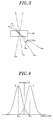
- Fig. 3 is an explanatory diagram of a principle for storing two holograms in the holographic plate 16 for implementing the tilt servo apparatus in accordance with the present invention.
- the holographic plate 16 is formed of a material, in which a hologram can be recorded, such as a photopolymer and a photorefractive crystal.
- a first tilt reference beam R TA and a first tilt signal beam S TA are projected onto the holographic plate 16 at a first tilt reference angle ⁇ TA and a first tilt signal angle, respectively, so that a holographic interference between the first tilt reference beam R TA and the first tilt signal beam S TA may be stored as a first hologram in the holographic plate 16.
- a second tilt reference beam R TB and a second tilt signal beam S TB are projected onto the holographic plate 16 at a second tilt reference angle ⁇ TB and a second tilt signal angle, respectively, so that another holographic interference between the second tilt reference beam R TB and the second tilt signal beam S TB may be stored as a second hologram in the holographic plate 16. Therefore, when a reference beam corresponding to the first tilt reference beam R TA is projected onto the holographic plate 16 at the first tilt reference angle ⁇ TA , the reference beam is diffracted to reconstruct a signal beam corresponding to the first tilt signal beam S TA at the first tilt signal angle.
- the reference beam is diffracted to reconstruct a signal beam corresponding to the second tilt signal beam S TB at the second tilt signal angle. It is preferable that all of the first tilt reference beam R TA , the second tilt reference beam R TB , the first tilt signal beam S TA and the second tilt signal beam S TB have a same wavelength as the reconstructing beam R and the reflected beam R*. Referring back to Fig.
- the first and the second tilt reference angle ⁇ TA and ⁇ TB are determined by a range of a reflection angle ⁇ of the reflected beam R * formed by a reflection of the reconstructing beam R from the digital storage medium 14 tilted within a tilt range.
- the digital storage medium 14 is tilted as the dotted dash line a so that the reflection angle ⁇ of the reflected beam R* is equal to the first tilt reference angle ⁇ TA
- the reflected beam R* is diffracted by the first hologram to generate only a first holographic diffracted beam H A * corresponding to the first tilt signal beam S TA generating no second holographic diffracted beam H B * corresponding to the second tilt signal beam S TB .
- the digital storage medium 14 is tilted as the double dotted dash line b so that the reflection angle ⁇ of the reflected beam R * is equal to the second tilt reference angle ⁇ TB , the reflected beam R * is diffracted by the second hologram to generate only the second holographic diffracted beam H B * corresponding to the second tilt signal beam S TB generating no first holographic diffracted beam H A * corresponding to the first tilt signal beam S TA . Consequently, it is preferable that the first and the second tilt reference angle ⁇ TA and ⁇ TB of the holographic plate 16 are determined according to an angular selectivity of the first and the second hologram stored in the holographic plate 16.
- Fig. 4 illustrates the angular selectivity of the first and the second hologram stored in the holographic plate 16 with respect to the reflection angle ⁇ of the reflected beam R * in accordance with the present invention.
- the second holographic diffracted beam H B * has a maximum intensity. Further, as the reflection angle ⁇ becomes greater or smaller than the second tilt reference angle ⁇ TB , the intensity of the second holographic diffracted beam H B * decreases rapidly and, in the end, if the reflection angle ⁇ is equal to the first tilt reference angle ⁇ TA , the intensity of the second holographic diffracted beam H B * becomes zero.
- both the first and the second holographic diffracted beam H A *, H B * are detected.
- the intensity of the first holographic diffracted beam H A * is equal to that of the second holographic diffracted beam H B * , it is determined that the digital storage medium 14 is in a normal state and, if not, an intensity difference between the first and the second holographic diffracted beam H A *, H B * can be used as a tilt servo signal.
- the first and the second detector 18, 20 detect the first and second holographic diffracted beam H A *, H B * generated in the holographic plate 16 to generate a first and a second detected signal, respectively.
- the first and second detected signal indicate two intensities of the first and the second holographic diffracted beam H A *, H B *, respectively.
- the tilt servo signal generator 22 generates the tilt servo signal by finding a difference between the first and the second detected signal.
- the tilt servo signal is used to adjust the mirror 12 so that an incidence angle of the reconstructing beam may be adjusted and, therefore, a tilt error of the digital storage medium 14 may be compensated.
- a rotational axis 24 of the digital storage medium 14 may be adjusted by using the tilt servo signal to compensate the tilt error of the digital storage medium 14 directly.
- a pick-up position of the reconstructed signal beam S formed by the diffraction of the reconstructing beam by the holographic interference pattern stored in the holographic storage medium may be compensated based on the tilt error of the holographic storage medium 14.
- a pick-up position of the reflected beam R * may be compensated.
- the reflected beam of the reconstructing beam used in the ROM system and the angular selectivity of the hologram are employed to detect and compensate the tilt error due to the wobbling of the digital storage medium in the ROM system and it is possible to reconstruct more reliable data.
Landscapes
- Physics & Mathematics (AREA)
- Optics & Photonics (AREA)
- Optical Recording Or Reproduction (AREA)
- Holo Graphy (AREA)
- Optical Head (AREA)
Applications Claiming Priority (2)
| Application Number | Priority Date | Filing Date | Title |
|---|---|---|---|
| KR2003091068 | 2003-12-15 | ||
| KR10-2003-0091068A KR100536721B1 (ko) | 2003-12-15 | 2003-12-15 | 홀로그래픽 롬 시스템의 디스크 틸트 제어장치 |
Publications (2)
| Publication Number | Publication Date |
|---|---|
| EP1544854A1 true EP1544854A1 (fr) | 2005-06-22 |
| EP1544854B1 EP1544854B1 (fr) | 2008-09-24 |
Family
ID=34511221
Family Applications (1)
| Application Number | Title | Priority Date | Filing Date |
|---|---|---|---|
| EP04011928A Expired - Lifetime EP1544854B1 (fr) | 2003-12-15 | 2004-05-19 | Servo-commande de basculement utilisée dans un système R.O.M. |
Country Status (6)
| Country | Link |
|---|---|
| US (1) | US7027196B2 (fr) |
| EP (1) | EP1544854B1 (fr) |
| JP (1) | JP2005182975A (fr) |
| KR (1) | KR100536721B1 (fr) |
| CN (1) | CN1296916C (fr) |
| DE (1) | DE602004016720D1 (fr) |
Cited By (2)
| Publication number | Priority date | Publication date | Assignee | Title |
|---|---|---|---|---|
| EP1843334A3 (fr) * | 2006-04-06 | 2008-05-28 | Daewoo Electronics Corporation | Appareil de reproduction d'informations optiques et procédé de reproduction d'informations optiques l'utilisant |
| EP2015295A1 (fr) * | 2007-07-10 | 2009-01-14 | Sharp Kabushiki Kaisha | Élément d'hologramme, appareil de fabrication d'élément d'hologramme, procédé de fabrication d'élément d'hologramme, et appareil de reconstruction d'hologramme utilisé pour reconstruire des informations |
Families Citing this family (7)
| Publication number | Priority date | Publication date | Assignee | Title |
|---|---|---|---|---|
| KR100676873B1 (ko) * | 2005-12-22 | 2007-02-02 | 주식회사 대우일렉트로닉스 | 광정보 재생장치, 광정보 기록재생장치, 이를 이용한 광틸팅방법 |
| KR100727779B1 (ko) * | 2006-04-06 | 2007-06-14 | 주식회사 대우일렉트로닉스 | 광정보 재생장치, 광정보 기록재생장치 및 이를 이용한광정보 재생방법 |
| JP2008097701A (ja) * | 2006-10-11 | 2008-04-24 | Sony Corp | 光ディスク装置及びディスクチルト補正方法、並びに光ディスク |
| JP4784473B2 (ja) * | 2006-10-13 | 2011-10-05 | ソニー株式会社 | 光ディスク装置及びディスクチルト補正方法、並びに光ディスク |
| JP4539766B2 (ja) * | 2008-08-13 | 2010-09-08 | ソニー株式会社 | ホログラム記録再生装置、ホログラム記録再生方法およびホログラム記録媒体 |
| KR20100135048A (ko) * | 2009-06-16 | 2010-12-24 | 삼성전자주식회사 | 경사 보상이 가능한 인코더, 이를 이용한 하드 디스크 드라이브 및 하드 디스크 드라이브를 위한 서보 트랙 기록 장치 |
| KR20130076769A (ko) * | 2011-12-28 | 2013-07-08 | 한국전자통신연구원 | 광 정보 처리장치 및 이의 제어방법 |
Citations (2)
| Publication number | Priority date | Publication date | Assignee | Title |
|---|---|---|---|---|
| EP1282119A1 (fr) * | 2000-03-29 | 2003-02-05 | Optware Corporation | Capteur optique |
| US20030198158A1 (en) * | 2002-04-17 | 2003-10-23 | Jae-Woo Roh | Apparatus and method for compensating wobble in holographic digital data storage system |
Family Cites Families (7)
| Publication number | Priority date | Publication date | Assignee | Title |
|---|---|---|---|---|
| US4478480A (en) * | 1982-12-27 | 1984-10-23 | Benson, Inc. | Holographic scanner spinner wobble correction system |
| JP3715443B2 (ja) * | 1998-08-27 | 2005-11-09 | パイオニア株式会社 | 光ピックアップ装置 |
| JP3456579B2 (ja) * | 2000-04-20 | 2003-10-14 | 日本電気株式会社 | 光ヘッド装置および光学式情報記録再生装置 |
| US6661769B2 (en) * | 2000-09-29 | 2003-12-09 | Matsushita Electric Industrial Co., Ltd. | Optical storage medium, a tilt detection apparatus, and a data recording and reproducing apparatus |
| JP2002230801A (ja) * | 2001-02-02 | 2002-08-16 | Pioneer Electronic Corp | 光ピックアップ装置 |
| JP2002216368A (ja) * | 2001-01-15 | 2002-08-02 | Sony Corp | 光ピックアップ装置及び光学ディスク装置 |
| JP4453213B2 (ja) * | 2001-03-30 | 2010-04-21 | 旭硝子株式会社 | 光ヘッド装置 |
-
2003
- 2003-12-15 KR KR10-2003-0091068A patent/KR100536721B1/ko not_active Expired - Fee Related
-
2004
- 2004-03-30 JP JP2004098390A patent/JP2005182975A/ja active Pending
- 2004-05-18 US US10/847,312 patent/US7027196B2/en not_active Expired - Fee Related
- 2004-05-19 DE DE602004016720T patent/DE602004016720D1/de not_active Expired - Lifetime
- 2004-05-19 EP EP04011928A patent/EP1544854B1/fr not_active Expired - Lifetime
- 2004-06-02 CN CNB2004100473707A patent/CN1296916C/zh not_active Expired - Fee Related
Patent Citations (2)
| Publication number | Priority date | Publication date | Assignee | Title |
|---|---|---|---|---|
| EP1282119A1 (fr) * | 2000-03-29 | 2003-02-05 | Optware Corporation | Capteur optique |
| US20030198158A1 (en) * | 2002-04-17 | 2003-10-23 | Jae-Woo Roh | Apparatus and method for compensating wobble in holographic digital data storage system |
Cited By (3)
| Publication number | Priority date | Publication date | Assignee | Title |
|---|---|---|---|---|
| EP1843334A3 (fr) * | 2006-04-06 | 2008-05-28 | Daewoo Electronics Corporation | Appareil de reproduction d'informations optiques et procédé de reproduction d'informations optiques l'utilisant |
| US7729224B2 (en) | 2006-04-06 | 2010-06-01 | Daewoo Electronics Corp. | Optical information reproducing apparatus and optical information reproducing method using the same |
| EP2015295A1 (fr) * | 2007-07-10 | 2009-01-14 | Sharp Kabushiki Kaisha | Élément d'hologramme, appareil de fabrication d'élément d'hologramme, procédé de fabrication d'élément d'hologramme, et appareil de reconstruction d'hologramme utilisé pour reconstruire des informations |
Also Published As
| Publication number | Publication date |
|---|---|
| US20050128541A1 (en) | 2005-06-16 |
| CN1296916C (zh) | 2007-01-24 |
| EP1544854B1 (fr) | 2008-09-24 |
| CN1629949A (zh) | 2005-06-22 |
| JP2005182975A (ja) | 2005-07-07 |
| US7027196B2 (en) | 2006-04-11 |
| KR100536721B1 (ko) | 2005-12-14 |
| DE602004016720D1 (de) | 2008-11-06 |
| KR20050059448A (ko) | 2005-06-21 |
Similar Documents
| Publication | Publication Date | Title |
|---|---|---|
| US5745473A (en) | Multiple data layer optical disk with recorded information identifying the type of tracking | |
| US5202875A (en) | Multiple data surface optical data storage system | |
| US6825960B2 (en) | System and method for bitwise readout holographic ROM | |
| EP1562185A1 (fr) | Appareil d'enregistrement et de reproduction d'hologrammes et support d'enregistrement holographiques | |
| WO2001073773A1 (fr) | Capteur optique | |
| JP4258029B2 (ja) | 光学記録媒体からの読み出し又は該媒体への書き込み用の装置 | |
| US7027196B2 (en) | Tilt servo apparatus for use in ROM system | |
| WO2005047988A1 (fr) | Systeme et procede de lecture bit par bit d'une rom holographique | |
| EP1531462B1 (fr) | Dispositif d'enregistrement et de reproduction d'hologrammes avec une masque | |
| JP2014026706A (ja) | ホログラフィックメモリ装置および参照光入射角度調整方法 | |
| US6584065B1 (en) | Information recording medium apparatus for forming the same and information recording and reproducing systems | |
| JP4631418B2 (ja) | ホログラム記録装置、ホログラム再生方法 | |
| EP1542215A2 (fr) | Appareil de lecture optique pour support de stockage de données digitales | |
| US8000207B2 (en) | Method for reproducing hologram | |
| US20060193024A1 (en) | Double facing double storage capacity | |
| JPH11250485A (ja) | 光ピックアップ装置 | |
| JP2008041230A (ja) | 情報記録媒体、情報記録装置および情報再生装置 | |
| JP2002140827A (ja) | 光ディスクおよび光ピックアップ調整装置 | |
| HK1008705B (en) | Multiple data surface optical medium and data storage system | |
| JP2013064810A (ja) | ホログラフィックメモリ再生装置、ホログラフィックメモリ再生方法およびホログラム記録媒体 | |
| HK1008704B (en) | Multiple data surface optical medium and data storage system | |
| WO2003091996A1 (fr) | Support double face a double capacite de |
Legal Events
| Date | Code | Title | Description |
|---|---|---|---|
| PUAI | Public reference made under article 153(3) epc to a published international application that has entered the european phase |
Free format text: ORIGINAL CODE: 0009012 |
|
| AK | Designated contracting states |
Kind code of ref document: A1 Designated state(s): AT BE BG CH CY CZ DE DK EE ES FI FR GB GR HU IE IT LI LU MC NL PL PT RO SE SI SK TR |
|
| AX | Request for extension of the european patent |
Extension state: AL HR LT LV MK |
|
| 17P | Request for examination filed |
Effective date: 20051109 |
|
| AKX | Designation fees paid |
Designated state(s): DE FR GB IT NL |
|
| 17Q | First examination report despatched |
Effective date: 20060314 |
|
| GRAP | Despatch of communication of intention to grant a patent |
Free format text: ORIGINAL CODE: EPIDOSNIGR1 |
|
| GRAC | Information related to communication of intention to grant a patent modified |
Free format text: ORIGINAL CODE: EPIDOSCIGR1 |
|
| GRAS | Grant fee paid |
Free format text: ORIGINAL CODE: EPIDOSNIGR3 |
|
| GRAA | (expected) grant |
Free format text: ORIGINAL CODE: 0009210 |
|
| AK | Designated contracting states |
Kind code of ref document: B1 Designated state(s): DE FR GB IT NL |
|
| REG | Reference to a national code |
Ref country code: GB Ref legal event code: FG4D |
|
| REF | Corresponds to: |
Ref document number: 602004016720 Country of ref document: DE Date of ref document: 20081106 Kind code of ref document: P |
|
| PLBE | No opposition filed within time limit |
Free format text: ORIGINAL CODE: 0009261 |
|
| STAA | Information on the status of an ep patent application or granted ep patent |
Free format text: STATUS: NO OPPOSITION FILED WITHIN TIME LIMIT |
|
| 26N | No opposition filed |
Effective date: 20090625 |
|
| REG | Reference to a national code |
Ref country code: DE Ref legal event code: R082 Ref document number: 602004016720 Country of ref document: DE Representative=s name: SAMSON & PARTNER, PATENTANWAELTE, DE |
|
| REG | Reference to a national code |
Ref country code: GB Ref legal event code: 732E Free format text: REGISTERED BETWEEN 20130404 AND 20130410 |
|
| REG | Reference to a national code |
Ref country code: DE Ref legal event code: R082 Ref document number: 602004016720 Country of ref document: DE Representative=s name: SAMSON & PARTNER PATENTANWAELTE MBB, DE Effective date: 20130313 Ref country code: DE Ref legal event code: R082 Ref document number: 602004016720 Country of ref document: DE Representative=s name: SAMSON & PARTNER, PATENTANWAELTE, DE Effective date: 20130313 Ref country code: DE Ref legal event code: R081 Ref document number: 602004016720 Country of ref document: DE Owner name: MAPLE VISION TECHNOLOGIES INC., CA Free format text: FORMER OWNER: DAEWOO ELECTRONICS CORP., SEOUL/SOUL, KR Effective date: 20130313 |
|
| REG | Reference to a national code |
Ref country code: FR Ref legal event code: TP Owner name: MAPLE VISION TECHNOLOGIES INC., CA Effective date: 20131226 |
|
| PGFP | Annual fee paid to national office [announced via postgrant information from national office to epo] |
Ref country code: GB Payment date: 20140514 Year of fee payment: 11 |
|
| PGFP | Annual fee paid to national office [announced via postgrant information from national office to epo] |
Ref country code: IT Payment date: 20140522 Year of fee payment: 11 Ref country code: FR Payment date: 20140509 Year of fee payment: 11 Ref country code: DE Payment date: 20140515 Year of fee payment: 11 Ref country code: NL Payment date: 20140510 Year of fee payment: 11 |
|
| REG | Reference to a national code |
Ref country code: DE Ref legal event code: R119 Ref document number: 602004016720 Country of ref document: DE |
|
| GBPC | Gb: european patent ceased through non-payment of renewal fee |
Effective date: 20150519 |
|
| PG25 | Lapsed in a contracting state [announced via postgrant information from national office to epo] |
Ref country code: IT Free format text: LAPSE BECAUSE OF NON-PAYMENT OF DUE FEES Effective date: 20150519 |
|
| REG | Reference to a national code |
Ref country code: NL Ref legal event code: MM Effective date: 20150601 |
|
| REG | Reference to a national code |
Ref country code: FR Ref legal event code: ST Effective date: 20160129 |
|
| PG25 | Lapsed in a contracting state [announced via postgrant information from national office to epo] |
Ref country code: GB Free format text: LAPSE BECAUSE OF NON-PAYMENT OF DUE FEES Effective date: 20150519 Ref country code: NL Free format text: LAPSE BECAUSE OF NON-PAYMENT OF DUE FEES Effective date: 20150601 Ref country code: DE Free format text: LAPSE BECAUSE OF NON-PAYMENT OF DUE FEES Effective date: 20151201 |
|
| PG25 | Lapsed in a contracting state [announced via postgrant information from national office to epo] |
Ref country code: FR Free format text: LAPSE BECAUSE OF NON-PAYMENT OF DUE FEES Effective date: 20150601 |