EP1544972B1 - Support de barres omnibus pour armoires électriques - Google Patents
Support de barres omnibus pour armoires électriques Download PDFInfo
- Publication number
- EP1544972B1 EP1544972B1 EP04078360A EP04078360A EP1544972B1 EP 1544972 B1 EP1544972 B1 EP 1544972B1 EP 04078360 A EP04078360 A EP 04078360A EP 04078360 A EP04078360 A EP 04078360A EP 1544972 B1 EP1544972 B1 EP 1544972B1
- Authority
- EP
- European Patent Office
- Prior art keywords
- wall
- seat
- module
- shaped
- coupling
- Prior art date
- Legal status (The legal status is an assumption and is not a legal conclusion. Google has not performed a legal analysis and makes no representation as to the accuracy of the status listed.)
- Expired - Lifetime
Links
- 230000008878 coupling Effects 0.000 claims description 39
- 238000010168 coupling process Methods 0.000 claims description 39
- 238000005859 coupling reaction Methods 0.000 claims description 39
- 239000012777 electrically insulating material Substances 0.000 claims description 6
- 230000000284 resting effect Effects 0.000 claims description 3
- 230000013011 mating Effects 0.000 claims 2
- 238000004519 manufacturing process Methods 0.000 description 4
- 230000008901 benefit Effects 0.000 description 3
- 239000000463 material Substances 0.000 description 2
- 229920001169 thermoplastic Polymers 0.000 description 2
- 229920001187 thermosetting polymer Polymers 0.000 description 2
- 239000004416 thermosoftening plastic Substances 0.000 description 2
- 230000002860 competitive effect Effects 0.000 description 1
- 239000004020 conductor Substances 0.000 description 1
- 239000000470 constituent Substances 0.000 description 1
- 230000005520 electrodynamics Effects 0.000 description 1
- 238000009434 installation Methods 0.000 description 1
- 239000002184 metal Substances 0.000 description 1
- 230000004048 modification Effects 0.000 description 1
- 238000012986 modification Methods 0.000 description 1
- 230000009467 reduction Effects 0.000 description 1
Images

Classifications
-
- H—ELECTRICITY
- H02—GENERATION; CONVERSION OR DISTRIBUTION OF ELECTRIC POWER
- H02G—INSTALLATION OF ELECTRIC CABLES OR LINES, OR OF COMBINED OPTICAL AND ELECTRIC CABLES OR LINES
- H02G5/00—Installations of bus-bars
- H02G5/02—Open installations
- H02G5/025—Supporting structures
Definitions
- the present invention relates to a supporting device for busbars in a cabinet for an electrical switchboard, said device having improved functions and characteristics.
- the bars are coupled geometrically to purposely designed devices that support the bars, insulating them electrically from one another, and enable their connection to the more resistant frame of the cabinet.
- said devices also enable the possible electrodynamic stresses produced by the flow of current in the bars to be discharged on the frame.
- Document DE 195 11 358 discloses a device according to the preamble of claim 1.
- the primary task of the present invention is to provide a supporting device for busbars in a cabinet for an electrical switchboard, which will enable the drawbacks referred to above to be overcome, and in particular which, as compared to the devices of a known type, will enable a number of configurations to be obtained, so increasing the flexibility of application.
- a purpose of the present invention is to provide a supporting device for busbars in a cabinet for an electrical switchboard, the structure of which may be obtained with an optimized number of parts that can be fitted to one another in a simplified way as compared to the devices of a known type.
- Another purpose of the present invention is to provide a supporting device for busbars in a cabinet for an electrical switchboard that is suited to a simplified assembly with the bars, as well as to fixing to the supporting structure, thus simplifying and reducing the installation steps and times.
- Not the least important purpose of the present invention is to provide a supporting device for busbars in a cabinet for an electrical switchboard that will present high reliability and be relatively easy to manufacture at competitive costs.
- a supporting device for busbars in a cabinet for an electrical switchboard comprising at least one first module having a shaped body designed to be connected to a supporting element of the cabinet, said first module being made substantially of electrically insulating material and having a first wall designed to be set resting on said supporting element and a second wall, along which there is defined at least one first coupling seat.
- the device according to the invention is characterized in that it comprises at least one second module having a shaped body made substantially of electrically insulating material having a third wall, along which there is defined at least one second coupling seat, and a fourth wall, along which there is defined at least one third coupling seat, said second module being operatively coupleable to said first module alternatively with said third or said fourth wall facing said second wall so that said first seat mates geometrically with said second or said third seat, so forming a seat for housing a busbar.
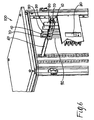
- the supporting device for busbars comprises at least one first module 1, designed to be connected to a supporting element, typically one of the elements making up the cabinet 100 of an electrical switchboard, for example a cross member 60 schematically illustrated in Figure 5 , and at least one second module 10 that is to be coupled to the first module 1 according to the modalities that will be described in detail in what follows.
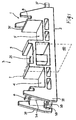
- the first module 1 has a shaped body made substantially of electrically insulating material, for example thermoplastic or thermosetting material, and has a first wall or face 2, designed to be set resting on the supporting element 60, and a second wall or face 3, along which there is defined at least one first coupling seat 4.
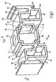
- the second module 10 also has a shaped body made substantially of electrically insulating material, for example thermoplastic or thermosetting material, and has a third wall or face 11, along which there is defined at least one second coupling seat 12, and a fourth wall or face 13, along which there is defined at least one third coupling seat 14.
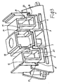
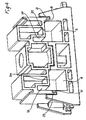
- the two modules 1 and 10 are shaped so that the second module 10 is operatively coupleable to the first module 1 or alternatively to the third wall 11 ( Figure 3 ) or to the fourth wall 13 ( Figure 4 ) facing the second wall 3 so that the first seat 4 (and corresponding boundary walls) mates geometrically with the second seat 12 (and corresponding walls) or the third seat 14 (and corresponding walls), so forming a seat for housing a busbar.
- a further fourth coupling seat 5 with the two seats 4 and 5 that are arranged substantially symmetrical to one another with respect to an imaginary middle plane of the first module 1 perpendicular to the second wall 3, designated for reasons of clarity of description in Figure 1 by the reference number 40.
- the two seats 4 and 5 have a U-shaped profile.
- the two seats could be differently configured, or else arranged along the wall 3 in different positions with respect to one another.
- both the two seats 12 and 15 defined on the wall 11 and the two seats 14 and 16 are arranged along the two corresponding walls 11 and 13 and are shaped so that, in the step of coupling of the two modules 1 and 10, each of them can be geometrically mated alternatively either with the first seat 4 or with the second seat 5, so forming in pairs two seats for housing two corresponding bars, as illustrated, for example, in Figures 3 and 4 .
- the four seats 12, 14, 15 and 16 have a U-shaped profile with the two branches of the U of lengths different from one another and profiles set two (12/14) by two (15/16) upside down with respect to one another.
- different alternatives are possible according to the needs of application, both as regards the configuration and as regards the mutual positioning.
- the two modules 1 and 10 are moreover shaped so as to present on their respective body geometrical coupling means that enable a direct reciprocal structural connection thereof, according to positions with respect to one another predefined according to desired configurations.
- the coupling means comprise first, second, and third means of connection defined, respectively, on the second wall 3, on the third wall 11, and on the fourth wall 13, and are configured so that the first means of connection will be coupleable alternatively to the second means of connection or the third means of connection.
- the first means of connection comprise at least one first step-shaped surface 6 and one first tooth 7, defined at the sides of the first seat 4 on sides opposite to one another in a position corresponding to the two edges of the first seat.
- the first means of connection moreover comprise a second step-shaped surface 8 and a second tooth 9 arranged at the sides of the fourth seat 5 on sides opposite to one another, with the first step-like surface 6 and the second step-like surface 8 that are arranged at the two ends of the second wall 3 symmetrically to one another with respect to the middle plane 40.
- the two teeth 7 and 9 are arranged preferably symmetrical to one another with respect to the middle plane 40.
- the second means of connection comprise at least one third step-shaped surface 17, defined in a position corresponding to an edge of the second seat 12 for coupling to one end of the wall 11, and at least one first U-shaped groove 18, in which the two branches of the U have, in the embodiment illustrated, lengths that are different from one another, with the longer branch connected to the seat 12 by a rectilinear stretch of wall 27.
- the second means of connection further comprise: a second groove 19, which is substantially L-shaped, is set in a position corresponding to an edge of the fifth seat 15 and is connected to the groove 18 by a rectilinear stretch of wall 28; and a fourth step-shaped surface 20, which is defined in a position corresponding to the other end of the wall 11 and is connected to the edge of the seat 15 by two rectilinear stretches of wall 29 and 30 set in an L-shaped arrangement with respect to one another.
- the third means of connection comprise: at least one fifth step-shaped surface 21, which is defined in a position corresponding to one end of the fourth wall 13 and is connected to the edge of the seat 14 by two rectilinear stretches of wall 31 and 32; and at least one sixth step-shaped surface 22, defined in a position corresponding to an edge of the third coupling seat 14.
- the third means of connection moreover comprise a seventh step-shaped surface 23, defined in a position corresponding to the other end of the fourth wall 13 in the proximity of an edge of the sixth coupling seat 16; and an eighth step-shaped surface 24, connected to the seat 16 and to the step-like surface 22 by means of two rectilinear stretches of wall, 34 and 33.
- said sixth and eighth step-shaped surfaces 22 and 24 are arranged substantially symmetrical to one another with respect to an imaginary middle plane 50 of the second module, substantially perpendicular to the walls 11-13.
- the two step-like surfaces 21 and 23 are arranged so that they are substantially symmetrical to one another with respect to the plane 50.
- first module 1 and on the second module 10 there are moreover preferably made two through channels, respectively 25 and 26, with a substantially rectilinear axis.
- Said channels are preferably defined along the directrices of, respectively, first-second walls and third-fourth walls, and are arranged in such a way as to be aligned to one another in the step of coupling of the two modules, for the purpose of receiving fixing means 70 for fixing to the supporting element 60, as illustrated in Figure 5 .
- the shaped body of the first module 1 further comprises a third side wall 35 and a fourth side wall 36 arranged transverse with respect to the first and second walls 2 and 3.
- said slotting means for coupling comprise at least one projecting tooth 37, for example with a rounded edge, defined on the wall 35, and at least one pair of projecting teeth 38 that delimit between them a U-shaped concavity.
- the device according to the invention enables various configurations to be obtained, according to the requirements of application.
- the module 10 in the assembly stage, can be coupled to the module 1 with: the step-like surfaces 17 and 20 that are coupled geometrically, respectively, to the step-like surfaces 6 and 8; the two U-shaped grooves 18 and 19, which are coupled to the two teeth 7 and 9; the two seats 4 and 5 (and corresponding boundary walls) that mate, respectively, with the seats 12 and 15 (and corresponding boundary walls), so in practice forming two L-shaped seats (of which in this case the walls 27 and 29 form a perimetral wall) inside which are housed and gripped two accordingly shaped busbars, illustrated in Figure 5 .
- the second module 10 could be coupled to the first module 1 by rotating it through 180° (in both directions of rotation indicated by the arrow 51) about an axis that lies in the middle plane 50, according to the joining walls 11-13.
- the step-like surface 20 is coupled to the step-like surface 6, the step-like surface 17 to the step-like surface 8, the groove 18 to the tooth 9, and the groove 19 to the tooth 7.
- the seat 15 (and corresponding boundary walls) is coupled to the seat 4 (and corresponding boundary walls), whilst the seat 12 (and corresponding boundary walls) is coupled to the seat 5 (and corresponding boundary walls), so forming also in this case two L-shaped housing seats (of which also in this case the walls 27 and 29 constitute a perimetral edge), but with the horizontal branches of the L oriented in a direction opposite to the configuration of Figure 3 , or to the similar configuration of Figure 5 for the pair of modules 1 and 10 on the left.
- the two modules 1 and 10 could be coupled to the module 10 rotated, starting from the position of Figure 2 , through 180° (in both directions of rotation, as indicated by the arrow 52) about an axis perpendicular to the plane of the drawing.
- the step-like surface couplings 23-6 we have: the step-like surfaces 21-8, the tooth 7-groove 19, and the tooth 9-groove 18.
- the seat 16 (and corresponding boundary walls) mates with the seat 4 (and corresponding walls), whilst the seat 14 (and corresponding boundary walls) mates with the seat 5 (and corresponding walls), so forming two seats for the housing of two bars.
- the two seats for housing the bars (of which in this case the stretches of wall 32 and 34 constitute a perimetral edge) are L-shaped but advantageously with the two branches of each L having thicknesses different from one another. This thus enables the same components to be used with bars of different thickness and hence that conduct higher currents.
- the module 10 can be rotated through 180° (in both directions of rotation, as indicated by the arrow 53) about an axis perpendicular to the middle plane 50 and directed according to the longitudinal development of the walls 11 and 13, thus bringing the seat 16 (and corresponding walls) to mate with the seat 5 (and corresponding walls) and the seat 14 (and corresponding walls) to mate with the seat 4 (and corresponding walls), forming in this way two seats for housing two L-shaped bars that are the same as the ones illustrated in Figure 4 , but with the horizontal branches of the L oriented on opposite sides.
- each pair of modules 1-10 can be coupled to a further pair of modules 1-10, by the slotting means provided on the transverse walls 31 and 32 of the module 1.
- the two modules 1, each coupled to the respective module 10 are coupled to one another by inserting the teeth 37 of one of the two modules 1 in the respective U-shaped concavities of the other, in an extremely simple and effective manner.
- fixing of the device to the cabinet 100 of the switchboard, in the example of Figure 5 to the cross member 60 is achieved using ordinary fixing means 70 inserted in the path defined by the two aligned channels 25 and 26, according to an extremely simple and effective solution.
- further fixing means 70 can be used on the sides of the modules by coupling them to the teeth 37 and/or 38 inserted in the spaces defined thereby.
- the assembly is then completed by electrically connecting the bars 90 to the apparatus or apparatuses 80 of the electrical switchboard.
- the device according to the invention fully accomplishes the task, as well as the purposes referred to in the preamble, by providing a series of advantages with respect to the known art.
- the two modules of the device by virtue of their innovative structure, enable an interchangeablity of coupling that is extremely flexible and simple, which makes possible a number of configurations, without having to resort to other components, and without even changing types or dimensions of the device itself, or of any of its constituent parts, as occurs, instead, in the devices of the known art.
- a further advantage is represented by the fact that it integrates in the structure of the two modules the mutual coupling means. In this way, there is a reduction in the number of components to be used and a simplification of the operations of assembly.
- the various means of connection could be prearranged in positions different from the ones described, or else be differently shaped, for example with the step-like surfaces rounded, or else with the teeth differently shaped, or with yet other shapes provided that they are compatible with the functions envisaged.
- each module could be modified; for example, modules with just one seat could be used, such as the portion of module 10 defined from the end on which there is defined one of the two step-like surfaces 17 or 20 as far as the part of the U-shaped grooves 19 or 20 and of the steps 24 or 22, and a corresponding portion of module 1 including a seat and the corresponding means of connection (the step-like surface 6/or 8, the tooth 7/ or 9).
- the module 1 or 10 could be made with a greater number of seats, for example by englobing in a single module the two pairs of modules 1 and 10, respectively.
Landscapes
- Patch Boards (AREA)
- Installation Of Indoor Wiring (AREA)
Claims (19)
- Dispositif de support pour barres omnibus dans une armoire d'un panneau de distribution électrique comprenant :- au moins un premier module (1) doté d'un corps profilé conçu pour être relié à un élément porteur de l'armoire, ledit premier module étant fabriqué sensiblement en un matériau isolant électriquement et présentant une première paroi (2) conçue pour être placée de manière à reposer sur ledit élément porteur, et une seconde paroi (3) le long de laquelle est défini au moins un premier siège de couplage (4),ledit dispositif de support comprenant au moins un deuxième module (10) doté d'un corps profilé fabriqué sensiblement en un matériau isolant électriquement qui présente une troisième paroi, le long de laquelle est défini au moins un deuxième siège de couplage (12, 15), et une quatrième paroi, le long de laquelle est défini au moins un troisième siège de couplage (14, 16), caractérisé par ledit deuxième module pouvant être couplé en fonctionnement audit premier module alternativement avec ladite troisième ou quatrième paroi faisant face à ladite deuxième paroi de sorte que ledit premier siège s'apparie géométriquement avec ledit deuxième ou ledit troisième siège pour former un siège pour le logement d'une barre omnibus.
- Dispositif selon la revendication 1, caractérisé en ce que lesdits premier et deuxième modules sont formés de sorte à présenter des moyens de couplage respectifs appariés ensemble géométriquement et conçus pour permettre une connexion structurelle directe dudit premier module audit deuxième module.
- Dispositif selon la revendication 2, caractérisé en ce que lesdits moyens de couplage comprennent des premiers, deuxièmes et troisièmes moyens de connexion définis respectivement sur lesdites deuxièmes, troisièmes et quatrièmes parois, lesdits premiers moyens de liaison pouvant être couplés alternativement auxdits deuxièmes ou troisièmes moyens de connexion.
- Dispositif selon la revendication 1, caractérisé en ce que sur ladite deuxième paroi, il est défini un autre quatrième siège de couplage, lesdits premiers et quatrièmes sièges étant disposés de manière sensiblement symétrique l'un à l'autre par rapport à un plan médian du premier module perpendiculairement à ladite deuxième paroi.
- Dispositif selon la revendication 4, caractérisé en ce que sur ladite troisième paroi, il est défini un cinquième siège de couplage, lesdits deuxièmes et cinquièmes sièges étant formés et disposés le long de ladite troisième paroi de sorte à permettre l'appariement géométrique de chacun alternativement avec ledit premier siège ou ledit quatrième siège pour former deux sièges pour le logement de deux barres correspondantes.
- Dispositif selon la revendication 4, caractérisé en ce que sur ladite quatrième paroi, il est défini un sixième siège de couplage, lesdits troisièmes et sixièmes sièges de couplage étant formés et disposés le long de ladite quatrième paroi de sorte à permettre l'appariement géométrique de chacun alternativement avec ledit premier ou deuxième siège pour former en paires deux sièges pour le logement de deux barres correspondantes.
- Dispositif selon la revendication 3, caractérisé en ce que lesdits premiers moyens de connexion comprennent au moins une première surface étagée et une première dent définie sur les côtés dudit premier siège sur des côtés opposés l'un à l'autre.
- Dispositif selon les revendications 4 et 7, caractérisé en ce que lesdits premiers moyens de connexion comprennent une deuxième surface étagée et une deuxième dent définie sur les côtés dudit quatrième siège sur des côtés opposés, lesdites premières et deuxièmes surfaces étagées étant placées sur les deux extrémités de ladite deuxième paroi de manière symétrique l'une à l'autre par rapport audit plan médian, lesdites premières et deuxièmes dents étant disposées de manière symétrique l'une à l'autre par rapport audit plan médian.
- Dispositif selon la revendication 3, caractérisé en ce que lesdits deuxièmes moyens de connexion comprennent au moins une troisième surface étagée définie dans une position correspondant à une arête dudit deuxième siège de couplage et au moins un premier canal en forme de U, dont les deux branches sont de longueurs différentes.
- Dispositif selon la revendication 9, caractérisé en ce que lesdits deuxièmes moyens de connexion comprennent un deuxième canal sensiblement en forme de L placé dans une position correspondant à une arête dudit cinquième siège et une quatrième surface étagée, lesdites deuxièmes et quatrièmes surfaces étagées étant définies dans des positions correspondant aux deux extrémités de ladite troisième paroi.
- Dispositif selon la revendication 3, caractérisé en ce que lesdits troisièmes moyens de connexion comprennent au moins une cinquième surface étagée définie dans une position correspondant à une extrémité de ladite quatrième paroi, et au moins une sixième surface étagée définie dans une position correspondant à une arête dudit troisième siège de couplage.
- Dispositif selon la revendication 11, caractérisé en ce que lesdits troisièmes moyens de connexion comprennent de plus une septième surface étagée définie dans une position correspondant à une extrémité de ladite quatrième paroi à proximité d'une arête dudit sixième siège de couplage.
- Dispositif selon la revendication 11, caractérisé en ce que lesdits troisièmes moyens de connexion comprennent au moins une huitième surface étagée, lesdites sixièmes et huitièmes surfaces étagées étant disposées de manière sensiblement symétrique par rapport à un plan médian du deuxième module sensiblement perpendiculairement à ladite quatrième paroi.
- Dispositif selon la revendication 1, caractérisé en ce que sur ledit premier module, il est défini un premier canal traversant avec un axe sensiblement rectiligne, ledit premier canal étant défini le long de la directrice des première et deuxième parois et étant conçu pour recevoir des moyens de fixation audit élément porteur.
- Dispositif selon la revendication 14, caractérisé en ce que sur ledit deuxième module, il est défini un deuxième canal traversant avec un axe sensiblement rectiligne, ledit deuxième canal traversant étant défini le long de la directrice des troisièmes et quatrièmes parois de sorte à être aligné avec ledit premier canal et recevoir lesdits moyens de fixation.
- Dispositif selon l'une ou plusieurs quelconques des revendications précédentes, caractérisé en ce que le corps profilé du premier module comprend des troisièmes et quatrièmes parois placées transversalement auxdites premières et deuxièmes parois, desquelles s'étendent, sur des côtés opposés l'un à l'autre, des moyens de rainurage respectifs pour le couplage à au moins un autre module.
- Dispositif selon la revendication 16, caractérisé en ce que lesdits moyens de rainurage pour le couplage comprennent au moins une dent en saillie avec une arête arrondie définie sur ladite troisième paroi transversale et au moins une paire de dents en saillie qui délimitent entre elles un siège en forme de U sur ladite quatrième paroi transversale.
- Dispositif selon l'une ou plusieurs quelconques des revendications précédentes, caractérisé en ce qu'il comprend une paire de premiers modules disposés à côté et reliés l'un à l'autre à l'aide de dits moyens de rainurage pour le couplage, et une paire de deuxièmes modules couplés chacun à un premier module correspondant.
- Panneau de distribution électrique comprenant une armoire, au moins un appareil électrique et une pluralité de barres omnibus, caractérisé en ce qu'il comprend au moins un dispositif de support pour lesdites barres omnibus selon l'une ou plusieurs quelconques des revendications précédentes.
Applications Claiming Priority (2)
| Application Number | Priority Date | Filing Date | Title |
|---|---|---|---|
| ITBG20030060 | 2003-12-17 | ||
| IT000060A ITBG20030060A1 (it) | 2003-12-17 | 2003-12-17 | Dispositivo di supporto per barre conduttrici in armadi per quadri elettrici. |
Publications (2)
| Publication Number | Publication Date |
|---|---|
| EP1544972A1 EP1544972A1 (fr) | 2005-06-22 |
| EP1544972B1 true EP1544972B1 (fr) | 2013-02-27 |
Family
ID=34509412
Family Applications (1)
| Application Number | Title | Priority Date | Filing Date |
|---|---|---|---|
| EP04078360A Expired - Lifetime EP1544972B1 (fr) | 2003-12-17 | 2004-12-10 | Support de barres omnibus pour armoires électriques |
Country Status (5)
| Country | Link |
|---|---|
| US (1) | US7433205B2 (fr) |
| EP (1) | EP1544972B1 (fr) |
| CN (1) | CN100595986C (fr) |
| ES (1) | ES2408120T3 (fr) |
| IT (1) | ITBG20030060A1 (fr) |
Cited By (1)
| Publication number | Priority date | Publication date | Assignee | Title |
|---|---|---|---|---|
| EP4597764A1 (fr) | 2024-01-31 | 2025-08-06 | ABB Schweiz AG | Agencement pour supporter et fixer des barres omnibus |
Families Citing this family (7)
| Publication number | Priority date | Publication date | Assignee | Title |
|---|---|---|---|---|
| DE102006031763A1 (de) | 2006-07-05 | 2008-01-10 | Siemens Ag | Stromschienenhalter und Stromverteilereinheit mit einem Stromschienenhalter |
| US7616431B2 (en) * | 2007-11-02 | 2009-11-10 | Eaton Corporation | Electrical enclosure and support assembly therefor |
| US8087621B2 (en) * | 2007-12-20 | 2012-01-03 | Airbus Deutschland Gmbh | Holder for fixing components, in particular lines, inside an aircraft without using holes |
| DE102008026507A1 (de) * | 2008-05-23 | 2009-11-26 | August Schmid | Geschlossenes Sammelschienensystem zur Niederspannungsverteilung |
| DE102013103441A1 (de) * | 2013-04-05 | 2014-10-09 | Eaton Industries (Austria) Gmbh | Modulare halterung fuer elektrische leiter |
| DE102022125430A1 (de) * | 2022-09-30 | 2024-04-04 | Webasto SE | Stromschienenanordnung, Fahrzeugbatterie und Herstellverfahren einer Stromschienenanordnung |
| DE202024102941U1 (de) | 2024-06-05 | 2024-06-11 | Abn Gmbh | Sammelschienenträger |
Family Cites Families (7)
| Publication number | Priority date | Publication date | Assignee | Title |
|---|---|---|---|---|
| FR2719718B1 (fr) * | 1994-05-06 | 1996-06-07 | Schneider Electric Sa | Dispositif de jeu de barres, notamment pour une armoire de distribution électrique. |
| DE19511358A1 (de) * | 1995-03-28 | 1996-10-02 | Kloeckner Moeller Gmbh | Stromschienenträger für Niederspannungs-Energieverteiler |
| DE19712363C1 (de) * | 1997-03-25 | 1998-06-10 | Loh Kg Rittal Werk | Halter für Stromsammelschienen eines Sammelschienensystems |
| FR2775542B1 (fr) * | 1998-02-27 | 2000-05-19 | Legrand Sa | Support de barre(s) a logement(s) pouvant recevoir des barres de sections transversales differentes |
| WO2000027008A1 (fr) * | 1998-10-30 | 2000-05-11 | Abb Ricerca S.P.A. | Dispositif de support et de fixation de barres-omnibus |
| EP1215789A1 (fr) * | 2000-12-18 | 2002-06-19 | GE Power Controls Belgium, besloten vennootschap met beperkte aansprakelijkheid | Système de barres omnibus pour distribution électrique |
| DE20315711U1 (de) * | 2003-10-13 | 2003-12-11 | Wöhner GmbH & Co. KG Elektrotechnische Systeme | Sammelschienenträger |
-
2003
- 2003-12-17 IT IT000060A patent/ITBG20030060A1/it unknown
-
2004
- 2004-12-10 ES ES04078360T patent/ES2408120T3/es not_active Expired - Lifetime
- 2004-12-10 EP EP04078360A patent/EP1544972B1/fr not_active Expired - Lifetime
- 2004-12-17 CN CN200410104679A patent/CN100595986C/zh not_active Expired - Fee Related
- 2004-12-17 US US11/013,806 patent/US7433205B2/en not_active Expired - Fee Related
Cited By (1)
| Publication number | Priority date | Publication date | Assignee | Title |
|---|---|---|---|---|
| EP4597764A1 (fr) | 2024-01-31 | 2025-08-06 | ABB Schweiz AG | Agencement pour supporter et fixer des barres omnibus |
Also Published As
| Publication number | Publication date |
|---|---|
| ES2408120T3 (es) | 2013-06-18 |
| US20050133679A1 (en) | 2005-06-23 |
| ITBG20030060A1 (it) | 2005-06-18 |
| EP1544972A1 (fr) | 2005-06-22 |
| CN100595986C (zh) | 2010-03-24 |
| US7433205B2 (en) | 2008-10-07 |
| CN1638221A (zh) | 2005-07-13 |
Similar Documents
| Publication | Publication Date | Title |
|---|---|---|
| US7104832B2 (en) | Modular electrical connector and method of using | |
| EP3066903B1 (fr) | Système d'assemblage de composants | |
| US20160285216A1 (en) | Bridging module for a profiled mounting rail | |
| US7090544B2 (en) | Modular electrical connector and method of using | |
| EP1956688B1 (fr) | Raccordement électrique dissimulé et de préférence étanche pour un rail d'un système de distribution électrique, prémonté avec un de ces rails. | |
| WO2013052366A1 (fr) | Bloc de bornes comprenant un ensemble de barre omnibus à combinateur/tableau de distribution à fusible | |
| US9691581B2 (en) | Fuse arrangement | |
| CN104518385B (zh) | 用于构造成共享至少一个电源轨的装置的连接器 | |
| US7433205B2 (en) | Supporting device for busbars in cabinets for electrical switchboards | |
| EP3164915B1 (fr) | Module d'interconnexion et d'isolation pour barres omnibus | |
| JP6425623B2 (ja) | 回路遮断器 | |
| KR101625153B1 (ko) | 멀티 부스바 시스템을 적용한 전동기 제어반 | |
| CN111211020B (zh) | 配电盘的触头组件 | |
| KR102146064B1 (ko) | 분전반용 연결 브라켓 및 이를 구비한 분전반 | |
| KR20080003842U (ko) | 배전반 | |
| FI72622C (fi) | Stroemanslutningsanordning foer aostadkommande av elektrisk anslutning mellan ledningar. | |
| US7121856B2 (en) | Device for connection of busbars to equipment of an electrical switchboard | |
| CN217692559U (zh) | 轨道式母线槽 | |
| WO2012114081A2 (fr) | Unité de connexion électrique modulaire | |
| JP2004328841A (ja) | ブスバー間の位置決め構造及び電気接続箱 | |
| EP1389816B2 (fr) | Boitier d'installation pour appareils électriques | |
| KR102879809B1 (ko) | 친환경 1/2 하프(Half) 인출형 유니트 기술을 적용한 모듈형 MCC | |
| WO2017183175A1 (fr) | Tableau de distribution d'alimentation en courant continu | |
| KR102528616B1 (ko) | 인터락 프리 몰드를 이용한 통합형 분배기 | |
| KR20170029878A (ko) | 부스바용 분기형 절연블록 |
Legal Events
| Date | Code | Title | Description |
|---|---|---|---|
| PUAI | Public reference made under article 153(3) epc to a published international application that has entered the european phase |
Free format text: ORIGINAL CODE: 0009012 |
|
| AK | Designated contracting states |
Kind code of ref document: A1 Designated state(s): AT BE BG CH CY CZ DE DK EE ES FI FR GB GR HU IE IS IT LI LT LU MC NL PL PT RO SE SI SK TR |
|
| AX | Request for extension of the european patent |
Extension state: AL BA HR LV MK YU |
|
| 17P | Request for examination filed |
Effective date: 20051010 |
|
| AKX | Designation fees paid |
Designated state(s): AT BE BG CH CY CZ DE DK EE ES FI FR GB GR HU IE IS IT LI LT LU MC NL PL PT RO SE SI SK TR |
|
| RAP1 | Party data changed (applicant data changed or rights of an application transferred) |
Owner name: ABB S.P.A. |
|
| GRAP | Despatch of communication of intention to grant a patent |
Free format text: ORIGINAL CODE: EPIDOSNIGR1 |
|
| GRAS | Grant fee paid |
Free format text: ORIGINAL CODE: EPIDOSNIGR3 |
|
| GRAA | (expected) grant |
Free format text: ORIGINAL CODE: 0009210 |
|
| AK | Designated contracting states |
Kind code of ref document: B1 Designated state(s): AT BE BG CH CY CZ DE DK EE ES FI FR GB GR HU IE IS IT LI LT LU MC NL PL PT RO SE SI SK TR |
|
| REG | Reference to a national code |
Ref country code: GB Ref legal event code: FG4D |
|
| REG | Reference to a national code |
Ref country code: CH Ref legal event code: EP |
|
| REG | Reference to a national code |
Ref country code: AT Ref legal event code: REF Ref document number: 598928 Country of ref document: AT Kind code of ref document: T Effective date: 20130315 |
|
| REG | Reference to a national code |
Ref country code: IE Ref legal event code: FG4D |
|
| REG | Reference to a national code |
Ref country code: DE Ref legal event code: R096 Ref document number: 602004041116 Country of ref document: DE Effective date: 20130425 |
|
| REG | Reference to a national code |
Ref country code: CH Ref legal event code: NV Representative=s name: ISLER AND PEDRAZZINI AG, CH |
|
| REG | Reference to a national code |
Ref country code: ES Ref legal event code: FG2A Ref document number: 2408120 Country of ref document: ES Kind code of ref document: T3 Effective date: 20130618 |
|
| REG | Reference to a national code |
Ref country code: AT Ref legal event code: MK05 Ref document number: 598928 Country of ref document: AT Kind code of ref document: T Effective date: 20130227 |
|
| REG | Reference to a national code |
Ref country code: LT Ref legal event code: MG4D |
|
| PG25 | Lapsed in a contracting state [announced via postgrant information from national office to epo] |
Ref country code: SE Free format text: LAPSE BECAUSE OF FAILURE TO SUBMIT A TRANSLATION OF THE DESCRIPTION OR TO PAY THE FEE WITHIN THE PRESCRIBED TIME-LIMIT Effective date: 20130227 Ref country code: BG Free format text: LAPSE BECAUSE OF FAILURE TO SUBMIT A TRANSLATION OF THE DESCRIPTION OR TO PAY THE FEE WITHIN THE PRESCRIBED TIME-LIMIT Effective date: 20130527 Ref country code: IS Free format text: LAPSE BECAUSE OF FAILURE TO SUBMIT A TRANSLATION OF THE DESCRIPTION OR TO PAY THE FEE WITHIN THE PRESCRIBED TIME-LIMIT Effective date: 20130627 Ref country code: LT Free format text: LAPSE BECAUSE OF FAILURE TO SUBMIT A TRANSLATION OF THE DESCRIPTION OR TO PAY THE FEE WITHIN THE PRESCRIBED TIME-LIMIT Effective date: 20130227 Ref country code: AT Free format text: LAPSE BECAUSE OF FAILURE TO SUBMIT A TRANSLATION OF THE DESCRIPTION OR TO PAY THE FEE WITHIN THE PRESCRIBED TIME-LIMIT Effective date: 20130227 |
|
| REG | Reference to a national code |
Ref country code: NL Ref legal event code: VDEP Effective date: 20130227 |
|
| PG25 | Lapsed in a contracting state [announced via postgrant information from national office to epo] |
Ref country code: SI Free format text: LAPSE BECAUSE OF FAILURE TO SUBMIT A TRANSLATION OF THE DESCRIPTION OR TO PAY THE FEE WITHIN THE PRESCRIBED TIME-LIMIT Effective date: 20130227 Ref country code: PL Free format text: LAPSE BECAUSE OF FAILURE TO SUBMIT A TRANSLATION OF THE DESCRIPTION OR TO PAY THE FEE WITHIN THE PRESCRIBED TIME-LIMIT Effective date: 20130227 Ref country code: PT Free format text: LAPSE BECAUSE OF FAILURE TO SUBMIT A TRANSLATION OF THE DESCRIPTION OR TO PAY THE FEE WITHIN THE PRESCRIBED TIME-LIMIT Effective date: 20130627 Ref country code: FI Free format text: LAPSE BECAUSE OF FAILURE TO SUBMIT A TRANSLATION OF THE DESCRIPTION OR TO PAY THE FEE WITHIN THE PRESCRIBED TIME-LIMIT Effective date: 20130227 Ref country code: GR Free format text: LAPSE BECAUSE OF FAILURE TO SUBMIT A TRANSLATION OF THE DESCRIPTION OR TO PAY THE FEE WITHIN THE PRESCRIBED TIME-LIMIT Effective date: 20130528 Ref country code: BE Free format text: LAPSE BECAUSE OF FAILURE TO SUBMIT A TRANSLATION OF THE DESCRIPTION OR TO PAY THE FEE WITHIN THE PRESCRIBED TIME-LIMIT Effective date: 20130227 |
|
| PG25 | Lapsed in a contracting state [announced via postgrant information from national office to epo] |
Ref country code: CZ Free format text: LAPSE BECAUSE OF FAILURE TO SUBMIT A TRANSLATION OF THE DESCRIPTION OR TO PAY THE FEE WITHIN THE PRESCRIBED TIME-LIMIT Effective date: 20130227 Ref country code: RO Free format text: LAPSE BECAUSE OF FAILURE TO SUBMIT A TRANSLATION OF THE DESCRIPTION OR TO PAY THE FEE WITHIN THE PRESCRIBED TIME-LIMIT Effective date: 20130227 Ref country code: SK Free format text: LAPSE BECAUSE OF FAILURE TO SUBMIT A TRANSLATION OF THE DESCRIPTION OR TO PAY THE FEE WITHIN THE PRESCRIBED TIME-LIMIT Effective date: 20130227 Ref country code: EE Free format text: LAPSE BECAUSE OF FAILURE TO SUBMIT A TRANSLATION OF THE DESCRIPTION OR TO PAY THE FEE WITHIN THE PRESCRIBED TIME-LIMIT Effective date: 20130227 Ref country code: NL Free format text: LAPSE BECAUSE OF FAILURE TO SUBMIT A TRANSLATION OF THE DESCRIPTION OR TO PAY THE FEE WITHIN THE PRESCRIBED TIME-LIMIT Effective date: 20130227 Ref country code: DK Free format text: LAPSE BECAUSE OF FAILURE TO SUBMIT A TRANSLATION OF THE DESCRIPTION OR TO PAY THE FEE WITHIN THE PRESCRIBED TIME-LIMIT Effective date: 20130227 |
|
| PG25 | Lapsed in a contracting state [announced via postgrant information from national office to epo] |
Ref country code: CY Free format text: LAPSE BECAUSE OF FAILURE TO SUBMIT A TRANSLATION OF THE DESCRIPTION OR TO PAY THE FEE WITHIN THE PRESCRIBED TIME-LIMIT Effective date: 20130227 |
|
| PLBE | No opposition filed within time limit |
Free format text: ORIGINAL CODE: 0009261 |
|
| STAA | Information on the status of an ep patent application or granted ep patent |
Free format text: STATUS: NO OPPOSITION FILED WITHIN TIME LIMIT |
|
| 26N | No opposition filed |
Effective date: 20131128 |
|
| PGFP | Annual fee paid to national office [announced via postgrant information from national office to epo] |
Ref country code: TR Payment date: 20131128 Year of fee payment: 10 |
|
| REG | Reference to a national code |
Ref country code: DE Ref legal event code: R097 Ref document number: 602004041116 Country of ref document: DE Effective date: 20131128 |
|
| PG25 | Lapsed in a contracting state [announced via postgrant information from national office to epo] |
Ref country code: MC Free format text: LAPSE BECAUSE OF FAILURE TO SUBMIT A TRANSLATION OF THE DESCRIPTION OR TO PAY THE FEE WITHIN THE PRESCRIBED TIME-LIMIT Effective date: 20130227 Ref country code: LU Free format text: LAPSE BECAUSE OF FAILURE TO SUBMIT A TRANSLATION OF THE DESCRIPTION OR TO PAY THE FEE WITHIN THE PRESCRIBED TIME-LIMIT Effective date: 20131210 |
|
| REG | Reference to a national code |
Ref country code: IE Ref legal event code: MM4A |
|
| PG25 | Lapsed in a contracting state [announced via postgrant information from national office to epo] |
Ref country code: IE Free format text: LAPSE BECAUSE OF NON-PAYMENT OF DUE FEES Effective date: 20131210 |
|
| PGFP | Annual fee paid to national office [announced via postgrant information from national office to epo] |
Ref country code: GB Payment date: 20141219 Year of fee payment: 11 Ref country code: ES Payment date: 20141226 Year of fee payment: 11 Ref country code: DE Payment date: 20141211 Year of fee payment: 11 |
|
| PGFP | Annual fee paid to national office [announced via postgrant information from national office to epo] |
Ref country code: FR Payment date: 20141219 Year of fee payment: 11 |
|
| PG25 | Lapsed in a contracting state [announced via postgrant information from national office to epo] |
Ref country code: HU Free format text: LAPSE BECAUSE OF FAILURE TO SUBMIT A TRANSLATION OF THE DESCRIPTION OR TO PAY THE FEE WITHIN THE PRESCRIBED TIME-LIMIT; INVALID AB INITIO Effective date: 20041210 |
|
| REG | Reference to a national code |
Ref country code: DE Ref legal event code: R119 Ref document number: 602004041116 Country of ref document: DE |
|
| GBPC | Gb: european patent ceased through non-payment of renewal fee |
Effective date: 20151210 |
|
| REG | Reference to a national code |
Ref country code: FR Ref legal event code: ST Effective date: 20160831 |
|
| PG25 | Lapsed in a contracting state [announced via postgrant information from national office to epo] |
Ref country code: GB Free format text: LAPSE BECAUSE OF NON-PAYMENT OF DUE FEES Effective date: 20151210 Ref country code: DE Free format text: LAPSE BECAUSE OF NON-PAYMENT OF DUE FEES Effective date: 20160701 |
|
| PG25 | Lapsed in a contracting state [announced via postgrant information from national office to epo] |
Ref country code: FR Free format text: LAPSE BECAUSE OF NON-PAYMENT OF DUE FEES Effective date: 20151231 |
|
| REG | Reference to a national code |
Ref country code: ES Ref legal event code: FD2A Effective date: 20170127 |
|
| PG25 | Lapsed in a contracting state [announced via postgrant information from national office to epo] |
Ref country code: ES Free format text: LAPSE BECAUSE OF NON-PAYMENT OF DUE FEES Effective date: 20151211 |
|
| PG25 | Lapsed in a contracting state [announced via postgrant information from national office to epo] |
Ref country code: TR Free format text: LAPSE BECAUSE OF NON-PAYMENT OF DUE FEES Effective date: 20151210 |
|
| PGFP | Annual fee paid to national office [announced via postgrant information from national office to epo] |
Ref country code: CH Payment date: 20181218 Year of fee payment: 15 |
|
| PGFP | Annual fee paid to national office [announced via postgrant information from national office to epo] |
Ref country code: IT Payment date: 20181220 Year of fee payment: 15 |
|
| REG | Reference to a national code |
Ref country code: CH Ref legal event code: PL |
|
| PG25 | Lapsed in a contracting state [announced via postgrant information from national office to epo] |
Ref country code: IT Free format text: LAPSE BECAUSE OF NON-PAYMENT OF DUE FEES Effective date: 20191210 |
|
| PG25 | Lapsed in a contracting state [announced via postgrant information from national office to epo] |
Ref country code: LI Free format text: LAPSE BECAUSE OF NON-PAYMENT OF DUE FEES Effective date: 20191231 Ref country code: CH Free format text: LAPSE BECAUSE OF NON-PAYMENT OF DUE FEES Effective date: 20191231 |