EP1545855B1 - Verfahren und anlage zur herstellung von längen vorisolierter rohre - Google Patents
Verfahren und anlage zur herstellung von längen vorisolierter rohre Download PDFInfo
- Publication number
- EP1545855B1 EP1545855B1 EP02758190A EP02758190A EP1545855B1 EP 1545855 B1 EP1545855 B1 EP 1545855B1 EP 02758190 A EP02758190 A EP 02758190A EP 02758190 A EP02758190 A EP 02758190A EP 1545855 B1 EP1545855 B1 EP 1545855B1
- Authority
- EP
- European Patent Office
- Prior art keywords
- pipe
- casing
- mixer head
- foam
- foaming
- Prior art date
- Legal status (The legal status is an assumption and is not a legal conclusion. Google has not performed a legal analysis and makes no representation as to the accuracy of the status listed.)
- Expired - Lifetime
Links
- 238000000034 method Methods 0.000 title claims abstract description 61
- 238000004519 manufacturing process Methods 0.000 title claims abstract description 15
- 239000006260 foam Substances 0.000 claims abstract description 69
- 238000005187 foaming Methods 0.000 claims abstract description 45
- 239000006261 foam material Substances 0.000 claims abstract description 10
- 238000005452 bending Methods 0.000 claims abstract description 4
- 230000001681 protective effect Effects 0.000 claims abstract description 4
- 239000004604 Blowing Agent Substances 0.000 claims description 12
- 239000007795 chemical reaction product Substances 0.000 claims description 11
- 239000012948 isocyanate Substances 0.000 claims description 5
- 150000002513 isocyanates Chemical class 0.000 claims description 5
- 229920005862 polyol Polymers 0.000 claims description 5
- 150000003077 polyols Chemical class 0.000 claims description 5
- 238000010438 heat treatment Methods 0.000 description 8
- 229920002635 polyurethane Polymers 0.000 description 7
- 239000004814 polyurethane Substances 0.000 description 7
- 125000006850 spacer group Chemical group 0.000 description 5
- 239000000463 material Substances 0.000 description 4
- 239000000203 mixture Substances 0.000 description 4
- XLYOFNOQVPJJNP-UHFFFAOYSA-N water Substances O XLYOFNOQVPJJNP-UHFFFAOYSA-N 0.000 description 4
- 239000012530 fluid Substances 0.000 description 3
- 239000004698 Polyethylene Substances 0.000 description 2
- 229910000831 Steel Inorganic materials 0.000 description 2
- 230000002349 favourable effect Effects 0.000 description 2
- 210000000497 foam cell Anatomy 0.000 description 2
- 238000009413 insulation Methods 0.000 description 2
- 238000012986 modification Methods 0.000 description 2
- 230000004048 modification Effects 0.000 description 2
- 229920000573 polyethylene Polymers 0.000 description 2
- 239000010959 steel Substances 0.000 description 2
- 230000032683 aging Effects 0.000 description 1
- 238000004140 cleaning Methods 0.000 description 1
- 230000001419 dependent effect Effects 0.000 description 1
- 230000000694 effects Effects 0.000 description 1
- 239000011810 insulating material Substances 0.000 description 1
- 239000012774 insulation material Substances 0.000 description 1
- 230000005923 long-lasting effect Effects 0.000 description 1
- -1 polyethylene Polymers 0.000 description 1
- 230000002250 progressing effect Effects 0.000 description 1
- 239000002689 soil Substances 0.000 description 1
Images
Classifications
-
- B—PERFORMING OPERATIONS; TRANSPORTING
- B29—WORKING OF PLASTICS; WORKING OF SUBSTANCES IN A PLASTIC STATE IN GENERAL
- B29C—SHAPING OR JOINING OF PLASTICS; SHAPING OF MATERIAL IN A PLASTIC STATE, NOT OTHERWISE PROVIDED FOR; AFTER-TREATMENT OF THE SHAPED PRODUCTS, e.g. REPAIRING
- B29C44/00—Shaping by internal pressure generated in the material, e.g. swelling or foaming ; Producing porous or cellular expanded plastics articles
- B29C44/02—Shaping by internal pressure generated in the material, e.g. swelling or foaming ; Producing porous or cellular expanded plastics articles for articles of definite length, i.e. discrete articles
- B29C44/12—Incorporating or moulding on preformed parts, e.g. inserts or reinforcements
- B29C44/18—Filling preformed cavities
-
- B—PERFORMING OPERATIONS; TRANSPORTING
- B29—WORKING OF PLASTICS; WORKING OF SUBSTANCES IN A PLASTIC STATE IN GENERAL
- B29C—SHAPING OR JOINING OF PLASTICS; SHAPING OF MATERIAL IN A PLASTIC STATE, NOT OTHERWISE PROVIDED FOR; AFTER-TREATMENT OF THE SHAPED PRODUCTS, e.g. REPAIRING
- B29C44/00—Shaping by internal pressure generated in the material, e.g. swelling or foaming ; Producing porous or cellular expanded plastics articles
- B29C44/02—Shaping by internal pressure generated in the material, e.g. swelling or foaming ; Producing porous or cellular expanded plastics articles for articles of definite length, i.e. discrete articles
- B29C44/10—Applying counter-pressure during expanding
- B29C44/105—Applying counter-pressure during expanding the counterpressure being exerted by a fluid
-
- B—PERFORMING OPERATIONS; TRANSPORTING
- B29—WORKING OF PLASTICS; WORKING OF SUBSTANCES IN A PLASTIC STATE IN GENERAL
- B29C—SHAPING OR JOINING OF PLASTICS; SHAPING OF MATERIAL IN A PLASTIC STATE, NOT OTHERWISE PROVIDED FOR; AFTER-TREATMENT OF THE SHAPED PRODUCTS, e.g. REPAIRING
- B29C44/00—Shaping by internal pressure generated in the material, e.g. swelling or foaming ; Producing porous or cellular expanded plastics articles
- B29C44/02—Shaping by internal pressure generated in the material, e.g. swelling or foaming ; Producing porous or cellular expanded plastics articles for articles of definite length, i.e. discrete articles
- B29C44/12—Incorporating or moulding on preformed parts, e.g. inserts or reinforcements
- B29C44/1228—Joining preformed parts by the expanding material
- B29C44/1242—Joining preformed parts by the expanding material the preformed parts being concentric
-
- B—PERFORMING OPERATIONS; TRANSPORTING
- B29—WORKING OF PLASTICS; WORKING OF SUBSTANCES IN A PLASTIC STATE IN GENERAL
- B29C—SHAPING OR JOINING OF PLASTICS; SHAPING OF MATERIAL IN A PLASTIC STATE, NOT OTHERWISE PROVIDED FOR; AFTER-TREATMENT OF THE SHAPED PRODUCTS, e.g. REPAIRING
- B29C44/00—Shaping by internal pressure generated in the material, e.g. swelling or foaming ; Producing porous or cellular expanded plastics articles
- B29C44/20—Shaping by internal pressure generated in the material, e.g. swelling or foaming ; Producing porous or cellular expanded plastics articles for articles of indefinite length
- B29C44/32—Incorporating or moulding on preformed parts, e.g. linings, inserts or reinforcements
- B29C44/322—Incorporating or moulding on preformed parts, e.g. linings, inserts or reinforcements the preformed parts being elongated inserts, e.g. cables
-
- F—MECHANICAL ENGINEERING; LIGHTING; HEATING; WEAPONS; BLASTING
- F16—ENGINEERING ELEMENTS AND UNITS; GENERAL MEASURES FOR PRODUCING AND MAINTAINING EFFECTIVE FUNCTIONING OF MACHINES OR INSTALLATIONS; THERMAL INSULATION IN GENERAL
- F16L—PIPES; JOINTS OR FITTINGS FOR PIPES; SUPPORTS FOR PIPES, CABLES OR PROTECTIVE TUBING; MEANS FOR THERMAL INSULATION IN GENERAL
- F16L59/00—Thermal insulation in general
- F16L59/14—Arrangements for the insulation of pipes or pipe systems
- F16L59/143—Pre-insulated pipes
Definitions
- the present invention relates to a method and plant for manufacturing lengths of pre-insulated pipes which are widely used to transport hot or cold fluids with the main object of doing so while maintaining the temperature of the fluid essentially constant.
- insulated pipes are being used to transport the hot water from a central heating plant to the individual households, and the pipes are usually placed directly in the soil or in underground ducts, which implies that a protective casing is normally required to encase the service pipe(s) and the insulating foam in order to make the insulated pipe tamperproof and impervious to water and gas.
- the district heating pipes shall comply with the requirements for at least 30 years of service lifetime; preferably at least 50 years.
- insulated pipes with uniform foam thickness and density are essential for the economy of district heating systems, and the foam cells should contain gas with as low thermal conductivity as possible.
- the mix-pull technique - or Misch-Ziehkopf-Technik - is known from e.g. WO 00/47387 in the name of Bayer Aktiengesellschaft and Hennecke GmbH.
- WO 00/47387 describes a method for manufacturing pre-insulated pipes comprising an inner pipe and an outer pipe and between them an intermediate annular space being filled with insulating polyurethane (PUR) foam, while the inner and outer pipes are being mechanically held in a tight grip securing the pipes in a stretched, concentric position to each other during the foaming process.
- the foaming process is making use of the mix-pull technique according to which foaming of the insulating foam material is carried out in the space between the inner and outer pipes concurrently with a lance with the mixer head being moved in axial direction relative to the pipe in a controllable manner.
- WO 00/47387 describes a way to avoid thermal bridges in the pre-insulated pipes by introducing a spacer of same material as the insulating foam around the pipe and midways between the end supports in order to compensate possible bending of the pipe due to own weight and the progressively injected foam.
- the spacers used were made of other materials with less favorable thermal conductivity.
- the process can also involve use of two mixer heads being withdrawn in opposite directions away from a central annular spacer member of PUR foam which becomes embedded in the injected foam.
- the said method makes it possible to manufacture an insulated pipe, wherein spacer members are not needed, because the section of pipe situated at the active foaming space is continuously being supported at the one end by the first closure member or the progressing front of cured foam material and in the other end is slidably supported by the mixer head. This means that an almost constant, short length of pipe and casing with little chance to bend will stay unsupported in the zone of still flowing foam mixture in front of the mixer head.
- the finished pipe can shortly after be removed so that a new pipe can advantageously be produced by means of the production plant and thereby a good capacity is secured.
- a method is provided, wherein a very efficient mixing of foam components into a reaction product is obtained by the characterizing features of claim 1.
- the insulating foam is a PUR foam provided by thorough mixing of an isocyanate and a polyol containing a blowing agent, e.g. cyclopenthane or a CFC gas.
- a blowing agent e.g. cyclopenthane or a CFC gas.
- the insulating foam is a PIR foam provided by thorough mixing of an isocyanate and a polyol containing a blowing agent, e.g. cyclopenthane or a CFC gas.
- PIR foam has usually a bad flowability but given the short flow path this foam can be used, and it is a very useful material by accepting even very high temperatures.
- an initial tension is exerted on the pipe thereby providing it with a slightly curved shape in order to counterbalance the foam pressure between service pipe and casing, or said tension can be exerted on the casing.
- the method according to the invention can let an initial torque be exerted on the mixer head or a part thereof thereby maintaining the pipe and the casing in a cylindrical shape during the foaming process.
- At least one piping is provided for supplying a blowing agent e.g. cyclopenthane or a CFC gas, which gas enters the mixing chamber and intermixes with the foam components coming from the nozzles.
- a blowing agent e.g. cyclopenthane or a CFC gas
- At least one piping is provided for supplying a gas of low thermal conductivity e.g. Ar into the foaming space thereby exerting a counterpressure on the foaming process
- a gas of low thermal conductivity e.g. Ar
- the counterpressure also provides for the reaction product to flow from the mixing chamber in a laminar flow, which hinders air becoming confined in the foam as cured.
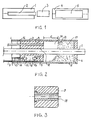
- the method according to the invention makes use of the mix-pull technique - also called Mischkopf-Zieh-Technik (MZT) - whereby a length of a pre-insulated pipe comprising at least one inner service pipe 2 with a surrounding protective casing 5 and an intermediary layer of insulating foam material, e.g. a PUR or PIR foam material, is manufactured and wherein the foaming of the insulating foam material is carried out in the space between the at least one pipe 2 and the surrounding casing 5 concurrently with the mixer head 3 being moved in axial direction relative to the pipe 2 in a controllable manner, and the casing 5 is supported centrally about the pipe 2.
- MZT Mischkopf-Zieh-Technik
- a length of a usually preheated pipe 2 is delivered to the first slide 1 while at the same time a corresponding casing 5 is delivered to the preheated fixture slide 4 and is axially aligned with the pipe 2.
- the pipe 2 is gripped by a carrier on a transportation device of common design (not shown) bringing the pipe axially forward through an opening in the mixer head 3, which is situated between the pipe 2 and the casing 5, and there the mixer head 3 is by optional means (not shown) locked or clamped on the pipe at a suitable distance from the front end and together they are moved into the casing 5.
- the casing 5 itself is fixed in the fixture slide 5 and a first closure member 6 or lid is moved into and held in engagement with the one end of the pipe 2 and casing 5 providing a tight closure of the opening between the pipe 2 and the casing 5 while also supporting said casing 5.
- the mixer head 3 is released from the pipe 2 and the foaming process can begin.
- the mixer head 3 is shown in details but out of scale in figure 2, where the head 3 is attached to a lance 7 for being pushed or pulled in axial directions. Further the head 3 is in the shape of an annular house in which is contained at least one mixing chamber 8 with one or more channels 9 connecting the mixer chamber 8 and the foaming space 10, the annular house having same rotational axis as the pipe 2 and the casing 5 and essentially showing the same cross section as exists between the pipe 2 and the casing 5.
- An axial opening 11 in the mixer head 3 fits around the pipe 2 and the mixer head 3 acts as a first support A for the casing 5, while the end of the casing 5 adjacent to the closure member 6 is initially supported by said member 6.
- the mixing chamber 8 In the mixing chamber 8 are provided axially oriented nozzles 12, 13 ejecting towards each other the foam components, a polyol and an isocyanate, respectively.
- the foam components are fed to the nozzles 12, 13 from high-pressure pumps (not shown) through respective piping 14, 15 and flow as a reaction product through the channel 9 into the foaming space 10, where the exoterm foaming process occurs developing the insulating foam 17.
- An advantageous feature according to the invention is the provision of piping 16 passing through the mixer head 3 and opening into the foaming space 10 and supplying a compressed gas, preferably a gas of low thermal conductivity e.g. Ar in said space 10.
- a compressed gas preferably a gas with low thermal conductivity e.g. Ar, is supplied to the foaming space 10 through the piping 16, thereby providing a counterpressure to control the foaming and making it possible to supply even more blowing agent, so the foam 17 can be produced with more of the preferred gas in the foam cells than normally permitted.
- a compressed gas preferably a gas with low thermal conductivity e.g. Ar
- the mixer head 3 As the mixer head 3 reaches the trailing end of the pipe 2, it will be fixed to the pipe and shortly after the delivery of reaction product into the foaming chamber 10 is shut off, and after a preset curing time the mixer head 3 is released from the pipe 2 and the pre-insulated pipe as formed is removed from the plant and a new production cycle can begin.
- an initial tension can be exerted on the pipe 2, thereby providing it with a slightly curved shape in order to counterbalance the foam pressure between service pipe and casing.
- an initial tension can be exerted on the casing 5, thereby providing it with a slightly curved shape in order to counterbalance the foam pressure between service pipe and casing.
- a preferred modification shows the radially inner surface of the mixer head 3 being provided with a separate guiding sleeve 18 as shown in figure 3, which sleeve 18 constitutes the sliding centering support for the pipe 2, wherein the inner diameter of the sleeve 18 is selected corresponding to the outer diameter of the chosen pipe and said sleeve 18 is exchangeable.
- pumps (not shown) and rigid pipings 14, 15, 16 for delivering gas and foam components to the foaming process, which pumps and pipings 14, 15, 16 are connected to the mixer head 3 and lance 7 such that they are slidable as one unit along the service pipe 2.
- This embodiment prevents to a large degree entanglement of machine parts with each other or neighbor parts and also cleaning will become easier.
Landscapes
- Engineering & Computer Science (AREA)
- General Engineering & Computer Science (AREA)
- Mechanical Engineering (AREA)
- Casting Or Compression Moulding Of Plastics Or The Like (AREA)
- Metal Extraction Processes (AREA)
- Thermal Insulation (AREA)
- Extrusion Moulding Of Plastics Or The Like (AREA)
- Processing And Handling Of Plastics And Other Materials For Molding In General (AREA)
Claims (15)
- Verfahren zur Herstellung einer Länge von vorisoliertem Rohr nach der Mischkopf-Zieh-Technik (MZT) und umfassend mindestens ein Dienstrohr (2) mit einem umgebenden schützenden Gehäuse (5) und einer zwischenliegenden Schicht von isolierendem Schaummaterial (17), wobei das Schäumen des isolierenden Schaummaterials (17) in dem Raum (10) zwischen dem mindestens einen Rohr (2) und dem umgebenden Gehäuse (5) durchgeführt wird, wobei gleichzeitig der Mischkopf (3) in axialer Richtung relativ zum Rohr (2) auf eine kontrollierte Weise bewegt wird und das Gehäuse (5) mittig um das Rohr (2) gestützt wird, wobei• das Rohr (2) zusammen mit dem Mischkopf (3) in ein Gehäuse (5) platziert wird,• ein erstes Verschlusselement (6) mit dem Ende des Rohrs (2) in Kontakt bewegt wird und einen Verschluss zum Öffnen zwischen dem Rohr (2) und dem Gehäuse (5) bereitstellt,• das Rohr (2) in einer festen Position gehalten wird,• der Mischkopf (3) die Schaumbestandteile in den axial vom ersten Verschlusselement (6) und dem Mischkopf (3) begrenzten Raum ausstößt,• wobei der Mischkopf (3) mit einer solchen Geschwindigkeit während des Schäumungsvorgangs axial weg von dem Verschlusselement (6) gezogen wird, dass der Schaum (17) durchgehend aushärtet, wodurch eine Stütze (B) für das Gehäuse in einem im Wesentlichen konstanten Abstand (C) vom Mischkopf (3) bereitgestellt wird und dadurch das vorisolierte Rohr am Biegen hindert,dadurch gekennzeichnet, dass• eine weitere Stütze (A) von dem Mischkopf (3) bereitgestellt wird, der in das Gehäuse (5) mit geringfügig größerem Innendurchmesser als dem Außendurchmesser des Mischkopfs (3) platziert wird, und die isolierenden Schaumbestandteile durch Leitungen (14, 15) in mindestens eine Mischkammer (8) im Mischkopf (3) geführt werden, um sie vor dem Ausstoß in den Schäumungsraum (10) vorzumischen.
- Verfahren nach Anspruch 1, dadurch gekennzeichnet, dass ein Gegendruck auf den Schäumungsvorgang ausgeübt wird, indem ein komprimiertes Gas in den Raum (10) eingeführt wird, in welchem der Schäumvorgang ausgeführt wird.
- Verfahren nach Anspruch 2, dadurch gekennzeichnet, dass das zugeführte Gas ein Gas geringer Wärmeleitfähigkeit ist, z.B. Argon.
- Verfahren nach einem der vorangegangenen Ansprüche, dadurch gekennzeichnet, dass ein Treibmittel, z.B. Cyclopenthan oder ein FCKW-Gas dem Reaktionsprodukt in der Mischkammer (8) zugeführt wird.
- Verfahren nach einem der vorangegangenen Ansprüche, dadurch gekennzeichnet, dass der Isolierschaum (17) ein PUR-Schaum ist, der durch gründliches Mischen eines Isocyanats und eines Polyols bereitgestellt wird, welches ein Treibmittel, z.B. Cyclopenthan oder ein FCKW-Gas, enthält.
- Verfahren nach einem der vorangegangenen Ansprüche, dadurch gekennzeichnet, dass der Isolierschaum (17) ein PIR-Schaum ist, der durch gründliches Mischen eines Isocyanats und eines Polyols bereitgestellt wird, welches ein Treibmittel, z.B. Cyclopenthan oder ein FCKW-Gas enthält.
- Verfahren nach einem der vorangegangenen Ansprüche, dadurch gekennzeichnet, dass eine anfängliche Spannung auf das Rohr (2) ausgeübt wird, wodurch es mit einer leichten Kurvenform versehen wird, um den Schaumdruck zwischen dem Dienstrohr und dem Gehäuse auszugleichen.
- Verfahren nach einem der vorangegangenen Ansprüche, dadurch gekennzeichnet, dass eine anfängliche Spannung auf das Gehäuse (5) ausgeübt wird, wodurch es mit einer leichten Kurvenform versehen wird, um den Schaumdruck zwischen dem Dienstrohr und dem Gehäuse auszugleichen.
- Verfahren nach einem der vorangegangenen Ansprüche, dadurch gekennzeichnet, dass ein anfängliches Drehmoment auf den Mischkopf (3) oder einen Teil davon ausgeübt wird, wodurch das Rohr (2) und das Gehäuse (5) während des Schäumungsvorgangs in einem gleichmäßigen radialen Abstand voneinander gehalten werden.
- Anlage zur Verwendung mit dem Verfahren entsprechend einem der vorangegangenen Ansprüche, wobei die Anlage eine erste längliche Gleitführung (1) für das zu einem Mischziehkopf (3) zu bewegende Rohr (2) und eine zweite längliche Gleitführung (4) umfasst, die geeignet ist, um ein Gehäuse (5) mit einem größeren Innendurchmesser als dem Außendurchmesser des Mischkopfes (3) aufzunehmen, wobei der Mischkopf (3) mindestens zwei Düsen (12, 13) aufweist und jede eine Schaumkomponente in eine Mischkammer (8) liefert, wobei vor dem Beginn des Schäumungsvorgangs das Reaktionsprodukt in der Mischkammer (8) in den mit Schaum zu füllenden Raum (10) eingeführt wird, dadurch gekennzeichnet, dass die Düsen (12, 13) in der Mischkammer (8) in der axialen Richtung des Rohrs (2) und des Gehäuses (5) aufeinander zu gerichtet sind, und dass das Reaktionsprodukt als laminarer Fluss durch einen Kanal (9) zugeführt wird, der die Mischkammer (8) und den Schäumungsraum (10) verbindet.
- Anlage nach Anspruch 10, dadurch gekennzeichnet, dass der Mischkopf (3) eine Mischkammer (8) umfasst und im Wesentlichen denselben Querschnitt zeigt, der zwischen dem Rohr (2) und dem Gehäuse (5) besteht, und dass die radial innere Oberfläche (11) des Mischkopfs (3) für die Dauer des Schäumungsvorgangs als Gleitzentrierstütze für das Gehäuse (5) relativ zum Rohr (2) dient.
- Anlage nach Anspruch 11, dadurch gekennzeichnet, dass die radial innere Oberfläche (11) des Mischkopfs mit einer separaten Führungshülse (18) versehen ist, die die Gleitzentrierstütze auf dem Rohr (2) darstellt, wobei der Innendurchmesser der Führungshülse (18) entsprechend dem Außendurchmesser des gewählten Rohrs (2) ausgewählt wird und die zentrierende Führungshülse (18) austauschbar ist.
- Anlage nach einem der Ansprüche 10 bis 12, dadurch gekennzeichnet, dass mindestens eine Leitung für die Zufuhr eines Treibmittels, z.B. Cyclopenthan oder eines FCKW-Gases, vorgesehen ist, wobei das Gas in die Mischkammer (8) eintritt und sich mit den von den Düsen (12, 13) kommenden Schaumbestandteilen vermischt.
- Anlage nach einem der Ansprüche 10 bis 13, dadurch gekennzeichnet, dass zumindestens eine Leitung (16) für die Zufuhr eines Gases niedriger Wärmeleitfähgigkeit, z.B. Argon, in den Schäumungsraum (10) vorgesehen ist, wodurch ein Gegendruck auf den Schäumungsvorgang ausgeübt wird.
- Anlage nach Ansprüchen 10 bis 14, und weiter Pumpen für die Zufuhr der Schaumbestandteile zu den jeweiligen Düsen (12, 13) im Mischkopf (3) umfassend, dadurch gekennzeichnet, dass die Pumpen mit dem Mischkopf (3) durch steife Leitungen (14, 15, 16) verbunden sind, und der Mischkopf (3) zusammen mit den Pumpen und den Leitungen für die Zufuhr der Schaumbestandteile als eine Einheit entlang des Dienstrohrs (2) verschiebbar ist.
Applications Claiming Priority (1)
| Application Number | Priority Date | Filing Date | Title |
|---|---|---|---|
| PCT/DK2002/000590 WO2004024411A1 (en) | 2002-09-11 | 2002-09-11 | Method and plant for manufacturing lengths of pre-insulated pipes |
Publications (2)
| Publication Number | Publication Date |
|---|---|
| EP1545855A1 EP1545855A1 (de) | 2005-06-29 |
| EP1545855B1 true EP1545855B1 (de) | 2007-03-14 |
Family
ID=31984945
Family Applications (1)
| Application Number | Title | Priority Date | Filing Date |
|---|---|---|---|
| EP02758190A Expired - Lifetime EP1545855B1 (de) | 2002-09-11 | 2002-09-11 | Verfahren und anlage zur herstellung von längen vorisolierter rohre |
Country Status (6)
| Country | Link |
|---|---|
| EP (1) | EP1545855B1 (de) |
| AT (1) | ATE356706T1 (de) |
| AU (1) | AU2002325208A1 (de) |
| DE (2) | DE02758190T1 (de) |
| DK (1) | DK1545855T3 (de) |
| WO (1) | WO2004024411A1 (de) |
Cited By (1)
| Publication number | Priority date | Publication date | Assignee | Title |
|---|---|---|---|---|
| EP4035855A1 (de) * | 2021-01-28 | 2022-08-03 | Sauerländer Spanplatten GmbH & Co. KG | Verfahren zum ausschäumen von röhrenspanplatten sowie eine röhrenspanplatte |
Families Citing this family (10)
| Publication number | Priority date | Publication date | Assignee | Title |
|---|---|---|---|---|
| DE102005050412A1 (de) * | 2005-10-19 | 2007-04-26 | Basf Ag | Polyurethanschaumstoffe zur Rohrdämmung |
| DE102005050413A1 (de) * | 2005-10-19 | 2007-04-26 | Basf Ag | Polyurethanschaumstoffe zur Rohrdämmung |
| DE102005050410A1 (de) * | 2005-10-19 | 2007-04-26 | Basf Ag | Polyurethanschaumstoffe zur Rohrdämmung |
| CN102962940A (zh) * | 2012-12-10 | 2013-03-13 | 孟扬 | 保温管均匀发泡装置 |
| CN105313256A (zh) * | 2014-07-13 | 2016-02-10 | 齐克先 | 一种保温管发泡工艺及聚氨酯料 |
| US10960588B2 (en) | 2016-06-08 | 2021-03-30 | Bayou Holdco, Inc. | System and method for applying moldable material to a pipe |
| US10357907B2 (en) | 2016-06-08 | 2019-07-23 | Bayou Holdco, Inc. | System and method for applying moldable material to a pipe by injecting moldable material from a movable support |
| US11999089B2 (en) | 2020-10-20 | 2024-06-04 | Bayou Holdco, Inc. | Transportable molding system for forming insulation on long pipes and related methods |
| US12338941B2 (en) | 2020-12-04 | 2025-06-24 | Bayou Holdco, Inc. | Molding system for insulated pipe |
| CN116572454A (zh) * | 2023-06-16 | 2023-08-11 | 山东庆达管业有限公司 | 一种绿色环保高效的氯化聚氯乙烯管道发泡工艺 |
Family Cites Families (5)
| Publication number | Priority date | Publication date | Assignee | Title |
|---|---|---|---|---|
| FR1396851A (fr) * | 1963-08-30 | 1965-04-23 | Tuyau isolant et son procédé de fabrication | |
| GB8901478D0 (en) * | 1989-01-24 | 1989-03-15 | Shell Int Research | Method for thermally insulating a pipeline |
| US6199593B1 (en) * | 1997-03-17 | 2001-03-13 | Basf Aktiengesellschaft | Production of pipes insulated with foams |
| DE19905275A1 (de) * | 1999-02-09 | 2000-08-10 | Hennecke Gmbh | Verfahren zur Herstellung wärmegedämmter Rohre |
| DE29903721U1 (de) * | 1999-03-02 | 1999-07-22 | Hartung, Matthias, Dipl.-Ing., 36124 Eichenzell | Vorrichtung zum Umschäumen von Rohren mit Außenrohr |
-
2002
- 2002-09-11 DK DK02758190T patent/DK1545855T3/da active
- 2002-09-11 WO PCT/DK2002/000590 patent/WO2004024411A1/en not_active Ceased
- 2002-09-11 DE DE02758190T patent/DE02758190T1/de active Pending
- 2002-09-11 AU AU2002325208A patent/AU2002325208A1/en not_active Abandoned
- 2002-09-11 DE DE60218907T patent/DE60218907T2/de not_active Expired - Fee Related
- 2002-09-11 EP EP02758190A patent/EP1545855B1/de not_active Expired - Lifetime
- 2002-09-11 AT AT02758190T patent/ATE356706T1/de not_active IP Right Cessation
Cited By (1)
| Publication number | Priority date | Publication date | Assignee | Title |
|---|---|---|---|---|
| EP4035855A1 (de) * | 2021-01-28 | 2022-08-03 | Sauerländer Spanplatten GmbH & Co. KG | Verfahren zum ausschäumen von röhrenspanplatten sowie eine röhrenspanplatte |
Also Published As
| Publication number | Publication date |
|---|---|
| ATE356706T1 (de) | 2007-04-15 |
| DK1545855T3 (da) | 2007-09-17 |
| DE60218907T2 (de) | 2007-11-29 |
| DE02758190T1 (de) | 2005-10-20 |
| EP1545855A1 (de) | 2005-06-29 |
| DE60218907D1 (de) | 2007-04-26 |
| WO2004024411A1 (en) | 2004-03-25 |
| AU2002325208A1 (en) | 2004-04-30 |
Similar Documents
| Publication | Publication Date | Title |
|---|---|---|
| EP1545855A1 (de) | Verfahren und anlage zur herstellung von längen vorisolierter rohre | |
| US4522578A (en) | Apparatus for introducing a foamable plastic insulation into the space defined by an inner core pipe and an outer casing pipe while maintaining the spacing of the pipes | |
| RU2187433C2 (ru) | Способ получения теплоизоляционного материала на основе синтактной пены, теплоизолированная труба и способ нанесения теплоизоляционного покрытия на внешнюю поверхность трубы | |
| EP2379933B1 (de) | Wickelbare styrolisolierung für ein rohr | |
| CA2115257C (en) | Foam-generating process and device | |
| EP2318749B1 (de) | Hochtemperaturfeste rohrisolierung | |
| JP5303115B2 (ja) | 熱絶縁された導管用の外筒を製造するための方法 | |
| JP2005238232A (ja) | スタティックミキサ及びその使用方法 | |
| US3444279A (en) | Method and apparatus for the insulation of conduit | |
| WO2014131127A1 (en) | High temperature resistant polysulfone insulation for pipe | |
| SE426039B (sv) | Sett att kontinuerligt framstella vermeisolerade ledningsror | |
| JP2011516621A5 (de) | ||
| US6010650A (en) | Production of pipes insulated with foams | |
| CN104067044A (zh) | 在连续制备过程中制备隔热套管的方法 | |
| RS59542B1 (sr) | Provodne cevi toplotno izolovane ćelijskim gasom koji sadrži hfo | |
| EP3023684B1 (de) | Wärmegedämmtes rohr sowie rohrleitungsabschnitt mit feuchtigkeitsschutz entlang der aussenfläche sowie entlang der enden | |
| KR101604609B1 (ko) | 폴리우레아 또는 폴리우레탄 코팅에 의한 코팅층을 형성하는 이중보온관의 제조장치 및 제조방법 | |
| JP4885480B2 (ja) | 発泡重合体の製造方法 | |
| US6199593B1 (en) | Production of pipes insulated with foams | |
| US11472152B2 (en) | Method for producing insulated pipes | |
| JPS6340995B2 (de) | ||
| CN210266339U (zh) | 一种ppr平行保温顺水三通 | |
| CN219442185U (zh) | 一种方便定心进行内填充的聚氨酯保温管生产工装 | |
| RU2172889C1 (ru) | Способ нанесения защитного покрытия на трубу | |
| CN119974460B (zh) | 超临界流体辅助高分子材料挤出成型机 |
Legal Events
| Date | Code | Title | Description |
|---|---|---|---|
| PUAI | Public reference made under article 153(3) epc to a published international application that has entered the european phase |
Free format text: ORIGINAL CODE: 0009012 |
|
| 17P | Request for examination filed |
Effective date: 20050411 |
|
| AK | Designated contracting states |
Kind code of ref document: A1 Designated state(s): AT BE BG CH CY CZ DE DK EE ES FI FR GB GR IE IT LI LU MC NL PT SE SK TR |
|
| AX | Request for extension of the european patent |
Extension state: AL LT LV MK RO SI |
|
| DET | De: translation of patent claims | ||
| DAX | Request for extension of the european patent (deleted) | ||
| GRAP | Despatch of communication of intention to grant a patent |
Free format text: ORIGINAL CODE: EPIDOSNIGR1 |
|
| GRAS | Grant fee paid |
Free format text: ORIGINAL CODE: EPIDOSNIGR3 |
|
| GRAA | (expected) grant |
Free format text: ORIGINAL CODE: 0009210 |
|
| AK | Designated contracting states |
Kind code of ref document: B1 Designated state(s): AT BE BG CH CY CZ DE DK EE ES FI FR GB GR IE IT LI LU MC NL PT SE SK TR |
|
| PG25 | Lapsed in a contracting state [announced via postgrant information from national office to epo] |
Ref country code: BE Free format text: LAPSE BECAUSE OF FAILURE TO SUBMIT A TRANSLATION OF THE DESCRIPTION OR TO PAY THE FEE WITHIN THE PRESCRIBED TIME-LIMIT Effective date: 20070314 Ref country code: LI Free format text: LAPSE BECAUSE OF FAILURE TO SUBMIT A TRANSLATION OF THE DESCRIPTION OR TO PAY THE FEE WITHIN THE PRESCRIBED TIME-LIMIT Effective date: 20070314 Ref country code: NL Free format text: LAPSE BECAUSE OF FAILURE TO SUBMIT A TRANSLATION OF THE DESCRIPTION OR TO PAY THE FEE WITHIN THE PRESCRIBED TIME-LIMIT Effective date: 20070314 Ref country code: CH Free format text: LAPSE BECAUSE OF FAILURE TO SUBMIT A TRANSLATION OF THE DESCRIPTION OR TO PAY THE FEE WITHIN THE PRESCRIBED TIME-LIMIT Effective date: 20070314 Ref country code: FI Free format text: LAPSE BECAUSE OF FAILURE TO SUBMIT A TRANSLATION OF THE DESCRIPTION OR TO PAY THE FEE WITHIN THE PRESCRIBED TIME-LIMIT Effective date: 20070314 |
|
| REG | Reference to a national code |
Ref country code: GB Ref legal event code: FG4D |
|
| REG | Reference to a national code |
Ref country code: CH Ref legal event code: EP |
|
| REF | Corresponds to: |
Ref document number: 60218907 Country of ref document: DE Date of ref document: 20070426 Kind code of ref document: P |
|
| REG | Reference to a national code |
Ref country code: IE Ref legal event code: FG4D |
|
| REG | Reference to a national code |
Ref country code: SE Ref legal event code: TRGR |
|
| PG25 | Lapsed in a contracting state [announced via postgrant information from national office to epo] |
Ref country code: ES Free format text: LAPSE BECAUSE OF FAILURE TO SUBMIT A TRANSLATION OF THE DESCRIPTION OR TO PAY THE FEE WITHIN THE PRESCRIBED TIME-LIMIT Effective date: 20070625 |
|
| PG25 | Lapsed in a contracting state [announced via postgrant information from national office to epo] |
Ref country code: PT Free format text: LAPSE BECAUSE OF FAILURE TO SUBMIT A TRANSLATION OF THE DESCRIPTION OR TO PAY THE FEE WITHIN THE PRESCRIBED TIME-LIMIT Effective date: 20070814 |
|
| NLV1 | Nl: lapsed or annulled due to failure to fulfill the requirements of art. 29p and 29m of the patents act | ||
| REG | Reference to a national code |
Ref country code: DK Ref legal event code: T3 |
|
| REG | Reference to a national code |
Ref country code: CH Ref legal event code: PL |
|
| EN | Fr: translation not filed | ||
| EN | Fr: translation not filed | ||
| PG25 | Lapsed in a contracting state [announced via postgrant information from national office to epo] |
Ref country code: SK Free format text: LAPSE BECAUSE OF FAILURE TO SUBMIT A TRANSLATION OF THE DESCRIPTION OR TO PAY THE FEE WITHIN THE PRESCRIBED TIME-LIMIT Effective date: 20070314 |
|
| PG25 | Lapsed in a contracting state [announced via postgrant information from national office to epo] |
Ref country code: CZ Free format text: LAPSE BECAUSE OF FAILURE TO SUBMIT A TRANSLATION OF THE DESCRIPTION OR TO PAY THE FEE WITHIN THE PRESCRIBED TIME-LIMIT Effective date: 20070314 |
|
| PLBE | No opposition filed within time limit |
Free format text: ORIGINAL CODE: 0009261 |
|
| STAA | Information on the status of an ep patent application or granted ep patent |
Free format text: STATUS: NO OPPOSITION FILED WITHIN TIME LIMIT |
|
| 26N | No opposition filed |
Effective date: 20071217 |
|
| PG25 | Lapsed in a contracting state [announced via postgrant information from national office to epo] |
Ref country code: MC Free format text: LAPSE BECAUSE OF NON-PAYMENT OF DUE FEES Effective date: 20070930 Ref country code: GR Free format text: LAPSE BECAUSE OF FAILURE TO SUBMIT A TRANSLATION OF THE DESCRIPTION OR TO PAY THE FEE WITHIN THE PRESCRIBED TIME-LIMIT Effective date: 20070615 Ref country code: IT Free format text: LAPSE BECAUSE OF FAILURE TO SUBMIT A TRANSLATION OF THE DESCRIPTION OR TO PAY THE FEE WITHIN THE PRESCRIBED TIME-LIMIT Effective date: 20070314 Ref country code: FR Free format text: LAPSE BECAUSE OF FAILURE TO SUBMIT A TRANSLATION OF THE DESCRIPTION OR TO PAY THE FEE WITHIN THE PRESCRIBED TIME-LIMIT Effective date: 20071102 |
|
| GBPC | Gb: european patent ceased through non-payment of renewal fee |
Effective date: 20070911 |
|
| PG25 | Lapsed in a contracting state [announced via postgrant information from national office to epo] |
Ref country code: IE Free format text: LAPSE BECAUSE OF NON-PAYMENT OF DUE FEES Effective date: 20070911 |
|
| PGFP | Annual fee paid to national office [announced via postgrant information from national office to epo] |
Ref country code: DK Payment date: 20080930 Year of fee payment: 7 |
|
| PG25 | Lapsed in a contracting state [announced via postgrant information from national office to epo] |
Ref country code: GB Free format text: LAPSE BECAUSE OF NON-PAYMENT OF DUE FEES Effective date: 20070911 Ref country code: FR Free format text: LAPSE BECAUSE OF FAILURE TO SUBMIT A TRANSLATION OF THE DESCRIPTION OR TO PAY THE FEE WITHIN THE PRESCRIBED TIME-LIMIT Effective date: 20070314 |
|
| PGFP | Annual fee paid to national office [announced via postgrant information from national office to epo] |
Ref country code: AT Payment date: 20080924 Year of fee payment: 7 |
|
| PG25 | Lapsed in a contracting state [announced via postgrant information from national office to epo] |
Ref country code: EE Free format text: LAPSE BECAUSE OF FAILURE TO SUBMIT A TRANSLATION OF THE DESCRIPTION OR TO PAY THE FEE WITHIN THE PRESCRIBED TIME-LIMIT Effective date: 20070314 |
|
| PGFP | Annual fee paid to national office [announced via postgrant information from national office to epo] |
Ref country code: DE Payment date: 20080930 Year of fee payment: 7 |
|
| PGFP | Annual fee paid to national office [announced via postgrant information from national office to epo] |
Ref country code: SE Payment date: 20080829 Year of fee payment: 7 |
|
| PG25 | Lapsed in a contracting state [announced via postgrant information from national office to epo] |
Ref country code: CY Free format text: LAPSE BECAUSE OF FAILURE TO SUBMIT A TRANSLATION OF THE DESCRIPTION OR TO PAY THE FEE WITHIN THE PRESCRIBED TIME-LIMIT Effective date: 20070314 |
|
| PG25 | Lapsed in a contracting state [announced via postgrant information from national office to epo] |
Ref country code: BG Free format text: LAPSE BECAUSE OF FAILURE TO SUBMIT A TRANSLATION OF THE DESCRIPTION OR TO PAY THE FEE WITHIN THE PRESCRIBED TIME-LIMIT Effective date: 20070614 Ref country code: LU Free format text: LAPSE BECAUSE OF NON-PAYMENT OF DUE FEES Effective date: 20070911 |
|
| PG25 | Lapsed in a contracting state [announced via postgrant information from national office to epo] |
Ref country code: TR Free format text: LAPSE BECAUSE OF FAILURE TO SUBMIT A TRANSLATION OF THE DESCRIPTION OR TO PAY THE FEE WITHIN THE PRESCRIBED TIME-LIMIT Effective date: 20070314 |
|
| EUG | Se: european patent has lapsed | ||
| PG25 | Lapsed in a contracting state [announced via postgrant information from national office to epo] |
Ref country code: AT Free format text: LAPSE BECAUSE OF NON-PAYMENT OF DUE FEES Effective date: 20090911 |
|
| PG25 | Lapsed in a contracting state [announced via postgrant information from national office to epo] |
Ref country code: DE Free format text: LAPSE BECAUSE OF NON-PAYMENT OF DUE FEES Effective date: 20100401 |
|
| REG | Reference to a national code |
Ref country code: DK Ref legal event code: EBP |
|
| PG25 | Lapsed in a contracting state [announced via postgrant information from national office to epo] |
Ref country code: DK Free format text: LAPSE BECAUSE OF NON-PAYMENT OF DUE FEES Effective date: 20090930 |
|
| PG25 | Lapsed in a contracting state [announced via postgrant information from national office to epo] |
Ref country code: SE Free format text: LAPSE BECAUSE OF NON-PAYMENT OF DUE FEES Effective date: 20090912 |
|
| PG25 | Lapsed in a contracting state [announced via postgrant information from national office to epo] |
Ref country code: DK Free format text: LAPSE BECAUSE OF NON-PAYMENT OF DUE FEES Effective date: 20110307 |