EP1545919B1 - Carrosserie de vehicule automobile et vehicule automobile - Google Patents
Carrosserie de vehicule automobile et vehicule automobile Download PDFInfo
- Publication number
- EP1545919B1 EP1545919B1 EP03776857A EP03776857A EP1545919B1 EP 1545919 B1 EP1545919 B1 EP 1545919B1 EP 03776857 A EP03776857 A EP 03776857A EP 03776857 A EP03776857 A EP 03776857A EP 1545919 B1 EP1545919 B1 EP 1545919B1
- Authority
- EP
- European Patent Office
- Prior art keywords
- door
- motor vehicle
- vehicle body
- pillar
- column
- Prior art date
- Legal status (The legal status is an assumption and is not a legal conclusion. Google has not performed a legal analysis and makes no representation as to the accuracy of the status listed.)
- Expired - Lifetime
Links
- 230000006835 compression Effects 0.000 claims 1
- 238000007906 compression Methods 0.000 claims 1
- 238000010276 construction Methods 0.000 description 1
- 238000006073 displacement reaction Methods 0.000 description 1
- 238000000034 method Methods 0.000 description 1
- 238000009420 retrofitting Methods 0.000 description 1
- 238000007789 sealing Methods 0.000 description 1
- 230000001960 triggered effect Effects 0.000 description 1
Images



Classifications
-
- B—PERFORMING OPERATIONS; TRANSPORTING
- B60—VEHICLES IN GENERAL
- B60J—WINDOWS, WINDSCREENS, NON-FIXED ROOFS, DOORS, OR SIMILAR DEVICES FOR VEHICLES; REMOVABLE EXTERNAL PROTECTIVE COVERINGS SPECIALLY ADAPTED FOR VEHICLES
- B60J5/00—Doors
- B60J5/04—Doors arranged at the vehicle sides
- B60J5/047—Doors arranged at the vehicle sides characterised by the opening or closing movement
-
- B—PERFORMING OPERATIONS; TRANSPORTING
- B60—VEHICLES IN GENERAL
- B60J—WINDOWS, WINDSCREENS, NON-FIXED ROOFS, DOORS, OR SIMILAR DEVICES FOR VEHICLES; REMOVABLE EXTERNAL PROTECTIVE COVERINGS SPECIALLY ADAPTED FOR VEHICLES
- B60J5/00—Doors
- B60J5/04—Doors arranged at the vehicle sides
- B60J5/047—Doors arranged at the vehicle sides characterised by the opening or closing movement
- B60J5/0477—Doors arranged at the vehicle sides characterised by the opening or closing movement with two doors opening in opposite direction
-
- B—PERFORMING OPERATIONS; TRANSPORTING
- B60—VEHICLES IN GENERAL
- B60J—WINDOWS, WINDSCREENS, NON-FIXED ROOFS, DOORS, OR SIMILAR DEVICES FOR VEHICLES; REMOVABLE EXTERNAL PROTECTIVE COVERINGS SPECIALLY ADAPTED FOR VEHICLES
- B60J5/00—Doors
- B60J5/04—Doors arranged at the vehicle sides
- B60J5/047—Doors arranged at the vehicle sides characterised by the opening or closing movement
- B60J5/0477—Doors arranged at the vehicle sides characterised by the opening or closing movement with two doors opening in opposite direction
- B60J5/0479—Doors arranged at the vehicle sides characterised by the opening or closing movement with two doors opening in opposite direction without B-pillar or releasable B-pillar, i.e. the pillar is moving with door
-
- E—FIXED CONSTRUCTIONS
- E05—LOCKS; KEYS; WINDOW OR DOOR FITTINGS; SAFES
- E05D—HINGES OR SUSPENSION DEVICES FOR DOORS, WINDOWS OR WINGS
- E05D15/00—Suspension arrangements for wings
- E05D15/48—Suspension arrangements for wings allowing alternative movements
- E05D15/50—Suspension arrangements for wings allowing alternative movements for opening at either of two opposite edges
- E05D15/507—Suspension arrangements for wings allowing alternative movements for opening at either of two opposite edges by detachment of the hinge from the wing or the frame
-
- E—FIXED CONSTRUCTIONS
- E05—LOCKS; KEYS; WINDOW OR DOOR FITTINGS; SAFES
- E05Y—INDEXING SCHEME ASSOCIATED WITH SUBCLASSES E05D AND E05F, RELATING TO CONSTRUCTION ELEMENTS, ELECTRIC CONTROL, POWER SUPPLY, POWER SIGNAL OR TRANSMISSION, USER INTERFACES, MOUNTING OR COUPLING, DETAILS, ACCESSORIES, AUXILIARY OPERATIONS NOT OTHERWISE PROVIDED FOR, APPLICATION THEREOF
- E05Y2900/00—Application of doors, windows, wings or fittings thereof
- E05Y2900/50—Application of doors, windows, wings or fittings thereof for vehicles
- E05Y2900/53—Type of wing
- E05Y2900/531—Doors
Definitions
- the invention relates to a motor vehicle body according to the preamble of claim 1.
- a motor vehicle body is known for example from US 5 367 828 A.
- the invention also relates to a motor vehicle having a motor vehicle body according to the invention.
- German Patent 464 139 a motor vehicle with a motor vehicle body with two arranged on one side of the vehicle doors and a detachable body B-pillar is known.
- the body B-pillar is located in a body-mounted position on the vehicle side between the two doors.
- the body B-pillar is attached to the rear of the two doors.
- the B-pillar may be provided with bolts at the top and bottom, which are engaged in the roof and base frames of the carbody.
- the front door is hinged to an A-pillar and opens against the normal forward direction of travel.
- the rear of the two doors, to which the B-pillar is attached, is hinged to a C-pillar and opens in the direction of travel.
- a detachable body B-pillar is known.
- the B-pillar is hung in a vehicle floor by means of a hook and attached to the roof frame by means of a locking lever.
- German patent application DE 38 10 762 A1 discloses a motor vehicle body in which a B-pillar in a rear, opposite to the direction of travel opening door is integrated.
- the B-pillar integrated into the rear door comprises locking devices, such as bolts, which can interact with a roof frame and a floor frame.
- a flexible vehicle body is to be created, which offers the vehicle occupants protection on the one hand and on the other hand is easy to load even with bulky items.
- a motor vehicle body is provided for this purpose, which has the features of claim 1.
- the opening of the doors is flexible and the first trajectory can be provided, for example, for a normal opening against the forward direction of travel. Characterized the known disadvantages of opening in the direction of travel doors are avoided while driving.
- the second movement path can be designed for a maximum possible door opening in order to be able to invite bulky goods while removing the B-pillar.
- the first trajectory is a conventional pivoting of the door and the second movement path can cause a pivoting or displacement, possibly parallelogram-like and in common with the B-pillar.
- a normal opening of the door opposite to the direction of travel is achieved and compared to a conventional, modern vehicle, no change of the opening operation in normal operation is required.
- the B-pillar stiffens the vehicle body, so that on the one hand, the lack of structural rigidity and sealing problem B-pillarless vehicles is avoided and on the other hand given an impact protection and easy seat belt attachment to the B-pillar is possible.
- the second articulation means for the alternative, second movement path for opening the door in the sense of easy loading bulky goods may be provided for example in the rear door frame area or on the roof frame.
- the B-pillar may be removed or pivoted together with the first door.
- multi-joint hinges could be used for more freedom in the choice of the trajectory.
- the first hinge means are designed as at least one door hinge, which connects the first door with the B-pillar.
- the second hinge means are designed as at least one swivel bracket and means are provided to the first door either by means of Swivel bracket pivotally connected to the body structure or release in the area of the swivel bracket.
- the second trajectory of the door can be designed more freely and yet a stable, simple structure can be realized.
- the swivel bracket is pivotally connected to the body structure and can selectively engage by means of a door lock on the first door.
- the door lock of the first door can engage a locking eye, which is connected by means of the lockable pivoting bracket pivotally connected to the body structure.
- the first door in the region of a front door edge is pivotally connected to the B-pillar and is selectively pivotally connected to the body structure in the region of an opposite rear door edge.
- An opening angle of the first, rear door and the second, front door is then expediently at least 90 °.
- means are provided for the controlled connection of the second articulation means to the first door or the body structure and for the subsequent release of the B pillar from the body structure.
- a controlled, successive unlocking of the B-pillar from the rest of the body structure, the locking of the door lock on the locking eye and the release of the swivel bracket can be done.
- the B-pillar is connected on the one hand with a roof frame and on the other hand with a sill by means of tie rods, push rods and / or fishing hooks.
- the problem underlying the invention is also solved by a motor vehicle having a motor vehicle body according to the invention.
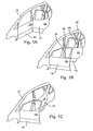
- FIGS. 1A, 1B and 1C a side part 10 of a motor vehicle body according to the invention with a first, rear door 12, a second, front door 14 and a detachable B-pillar 16 is shown.
- the front door 14 is struck by means of conventional door hinges on the side part 10 in the region of an A-pillar and a door lock of the front door 14 engages in a locking eye 18 on the B-pillar 16 a.
- the rear door 12 is struck in a conventional manner by means of two door hinges on the B-pillar 16 and opens as a result, as the front door 14, against the forward direction of travel.
- Such an opening counter to the direction of travel has the advantage during driving that the doors 12, 14 are closed by the wind and consequently can not spring open unexpectedly.
- the door lock of the rear door 12 engages in a closing eye 20, which is arranged in the region of a C-pillar of the side part 10.
- the doors are opened in the normal operation shown in a completely conventional manner and opening of the front door 14 and the rear door 12 is possible independently of one another.
- the roof frame of the side part 10 is supported against the sill area and as a result, the vehicle body has a relation to conventional bodies undiminished rigidity and offers protection in the event of an impact.
- a safety belt can be attached to the B-pillar 16.
- the B-pillar 16 as well as the rear door 12 and a rear fender of the side part 10 can be seen in each case.
- the rear door 12 is hinged by means of conventional door hinges 22 on the B-pillar 16.
- a door lock 24 of the rear door 12 engages in a known manner to a closing eye 26, which is arranged on the rear edge of the door frame in the side part 10.
- the locking eye 26 is connected to a swivel bracket 28, which in turn is pivotally connected to the side part 10 at a pivot point 30.
- a swivel bracket 28 which in turn is pivotally connected to the side part 10 at a pivot point 30.
- the locking eye 26 and / or the swivel bracket 28 is locked, so that no relative movement between the rear edge of the door frame of the side part 10 and the locking eye 26 can occur.
- the door 12 is securely held in the closed position shown in FIG. 2A on the side part 10. Since the B-pillar 16 in the normal operation shown securely connected to the side part 10 and, for example, is locked, the vehicle body according to the invention behaves in a vehicle collision in the same way as a conventional motor vehicle body without releasable B-pillar.
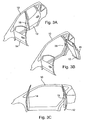
- FIGS. 3A, 3B and 3C show the side panel 10 with the doors 12 and 14 and the B pillar 16 of the vehicle body of Figs. 1A, 1B and 1C upon opening the doors 12 and 14 for maximum door opening.
- the front door 14 is opened up to an opening angle of approximately 90 °.
- the locks of the B-pillar 16 on the sill and the roof frame of the side part 10 are released, provided that the door lock of the rear door 12 is locked with the locking eye.
- the locking of the locking eye and / or the swivel bracket on the side part 10 are released, so that, as can be seen in Fig. 3B, the rear door 12 together with the B-pillar 16 by means of the pivot bracket 28 to the C-pillar of the side part 10 can be pivoted.
- the B-pillar 16 is held by means of conventional door hinges on the door 12.
- the rear door 12 can also be opened by means of the pivoting bracket 28 at an angle of 90 °, so that for loading bulky objects or, for example, an expansion of the seats, the entire, maximum door opening in the side part 10 is available without the B-pillar 16 could impede a loading process.
- FIGS. 4A and 4B show the B-pillar 16, the rear door 12, and the rear fender of the side member 10 when the rear door 12 is opened for maximum door opening against normal Forward direction of the motor vehicle.
- FIG. 4A shows the closed state of the rear door 12, which has already been shown in Fig. 2A.
- the Locking the B-pillar 16 are solved on the side part 10 and a locking of the locking eye 26 and / or the pivot bracket 28 on the side part 10 is released.
- the locks of the B-pillar 16 may only be solved when the door lock 24 of the rear door 12 is engaged in the locking eye 26.
- the rear door 12 can be pivoted about the pivot point 30 of the pivot bracket 28 to an opening angle of about 90 °.
- the B-pillar 16 is held by the conventional door hinges 22 on the door 12.
- the locking eye 26 can be further provided in Fig. 4A only dashed lines indicated support members 32 to keep the rear door 12 when opening securely on the swivel bracket 28.
- the B-pillar 16 has recesses 34 and 36 which can be pushed onto matching projections on the side part of the vehicle body and ensure a secure hold of the B-pillar 16 on the side part.
- a catch hook 38 is provided in the region of the upper recess, which can engage in a matching opening on the side part 10.
- the catch hook 38 is connected by means of a pull rod with a lever 40. By operating the lever 40, similar to the locking of a convertible roof, the catch hook 38 and thus the B-pillar 16 can be clamped against the side part.
- a latch 42 is provided, which is also connected by means of an actuating rod to the lever 40.
- the catch hook 38 is pulled in Fig. 5 down and at the same time the latch 42 is pushed down.
- the actuation of the lever 40 can take place either manually or by means of an electrically activatable device, for example a lifting magnet 44.
- a central control unit 46 contains as inputs a command to prepare the opening of the rear door 12 for maximum door opening. Such a command can be triggered, for example, by a driver. Furthermore, the control unit 46 receives input signals about the driving state of the vehicle. For example, the unlocking of the B-pillar 16 can only take place when the vehicle is stationary and the ignition is switched off. The control unit 46 also receives an input signal as to whether the door lock 24 of the rear door 12 is securely locked to the locking eye 26 on the side part.
- the control unit 46 Given the required conditions for opening the rear door 12 for a maximum door opening, the control unit 46 first issues a command to the lifting magnet 44, which thereupon, as shown schematically in FIG. 5, the locks of the B-pillar 16th on the side part of the vehicle body triggers. At the same time, the control unit 46 can release the locking of the swivel bracket 28 shown in FIGS. 4A and 4B and / or the closing eye 26 with the vehicle body. After releasing the locks of the B-pillar 16 and the pivoting bracket and / or the locking eye 26, the rear door 12 can then be opened to the rear around the swivel bracket, as shown in Fig. 3B.
- the control unit 46 expediently blocks the locking of the door lock 24 with the locking eye 26 as soon as the locks of the B-pillar with the side part of the vehicle body are released. In this way it can be prevented that the rear door 12 accidentally is released by pressing a door handles of the locking eye 26 and the swivel bracket.
- the control unit 46 After the door 12 is closed again and the B-pillar 16 is disposed at the intended position between the roof frame and sill of the side part, the control unit 46 provides a corresponding request command for the locking of the B-pillar 16 on the side part and the lock of Swivel bracket and / or the locking eye 26 on the door frame of the side part. Thereafter, the lock of the door lock 24 can be released and the rear door 12 can be opened again in a normal, conventional manner. At the same time, for example, the ignition of the motor vehicle can be released again for driving.
Landscapes
- Engineering & Computer Science (AREA)
- Mechanical Engineering (AREA)
- Body Structure For Vehicles (AREA)
- Lock And Its Accessories (AREA)
Claims (9)
- Carrosserie de véhicule automobile comprenant au moins deux portières (12, 14) disposées sur un côté de véhicule et une colonne B de carrosserie (16) disposée dans une position solidaire de la carrosserie sur le côté de véhicule entre les deux portières (12, 14), dans laquelle une première des deux portières (12, 14) peut être ouverte soit au moyen de premiers moyens d'articulation (22) suivant une première trajectoire soit au moyen de deuxièmes moyens d'articulation (28) suivant une deuxième trajectoire, les premiers moyens d'articulation (22) étant prévus sur la colonne B (16) pour l'articulation pivotante de la première portière (12), et les deuxièmes moyens d'articulation (28) étant prévus au niveau d'un point de la carrosserie différent de la colonne B (16) pour l'articulation pivotante de la première portière (12), caractérisée en ce que la colonne B de carrosserie (16) est déblocable et pivotante, à l'état débloqué, conjointement avec la première portière (12) .
- Carrosserie de véhicule automobile selon la revendication 1, caractérisée en ce que les premiers moyens d'articulation présentent la forme d'au moins une charnière de portière (22) qui relie la première portière (12) à la colonne B (16).
- Carrosserie de véhicule automobile selon la revendication 1 ou 2, caractérisée en ce que les deuxièmes moyens d'articulation présentent la forme d'au moins un arceau pivotant (28), et des moyens (24, 26) sont prévus pour au choix relier en pivotement la première portière (12) au moyen de l'arceau pivotant (28) à la structure de carrosserie (10) ou pour la débloquer dans la zone de l'arceau pivotant.
- Carrosserie de véhicule automobile selon la revendication 3, caractérisée en ce que l'arceau pivotant (28) est relié en pivotement à la structure de carrosserie (10) et peut intervenir sur la première portière (12) au moyen d'une serrure de portière (24).
- Carrosserie de véhicule automobile selon la revendication 4, caractérisée en ce que la serrure de portière (24) de la première portière (12) peut intervenir sur un oeillet de fermeture (26) qui est relié en pivotement à la structure de carrosserie (10) au moyen de l'arceau pivotant (28) blocable.
- Carrosserie de véhicule automobile selon l'une quelconque des revendications précédentes, caractérisée en ce que la première portière (12), dans la zone d'une arête de portière avant, est reliée en pivotement à la colonne B (16) et, dans la zone d'une arête de portière arrière située en face, peut être reliée au choix en pivotement à la carrosserie de véhicule (10) .
- Carrosserie de véhicule automobile selon l'une quelconque des revendications précédentes, caractérisée en ce que des moyens (44, 46, 48) sont prévus pour relier de manière commandée les deuxièmes moyens d'articulation (28) à la première portière (12) ou à la structure de carrosserie et pour ensuite débloquer la colonne B (16) de la structure de carrosserie (10).
- Carrosserie de véhicule automobile selon l'une quelconque des revendications précédentes, caractérisée en ce que la colonne B (16) peut être reliée d'une part à un cadre de toit et d'autre part à un seuil de porte au moyen de tirants, de tiges de compression et/ou de crochets d'attache (38).
- Véhicule automobile, caractérisé par une carrosserie de véhicule automobile selon l'une quelconque des revendications précédentes.
Applications Claiming Priority (3)
| Application Number | Priority Date | Filing Date | Title |
|---|---|---|---|
| DE10243898A DE10243898B4 (de) | 2002-09-21 | 2002-09-21 | Türanordnung bei einer Kraftfahrzeugkarosserie |
| DE10243898 | 2002-09-21 | ||
| PCT/EP2003/009608 WO2004028884A2 (fr) | 2002-09-21 | 2003-08-29 | Carrosserie de vehicule automobile et vehicule automobile |
Publications (2)
| Publication Number | Publication Date |
|---|---|
| EP1545919A2 EP1545919A2 (fr) | 2005-06-29 |
| EP1545919B1 true EP1545919B1 (fr) | 2006-03-15 |
Family
ID=31983966
Family Applications (1)
| Application Number | Title | Priority Date | Filing Date |
|---|---|---|---|
| EP03776857A Expired - Lifetime EP1545919B1 (fr) | 2002-09-21 | 2003-08-29 | Carrosserie de vehicule automobile et vehicule automobile |
Country Status (6)
| Country | Link |
|---|---|
| US (1) | US20060125284A1 (fr) |
| EP (1) | EP1545919B1 (fr) |
| JP (1) | JP2005538896A (fr) |
| DE (2) | DE10243898B4 (fr) |
| ES (1) | ES2258737T3 (fr) |
| WO (1) | WO2004028884A2 (fr) |
Cited By (1)
| Publication number | Priority date | Publication date | Assignee | Title |
|---|---|---|---|---|
| DE102007033929B4 (de) | 2006-09-20 | 2022-01-05 | Volkswagen Ag | Kraftfahrzeugkarosserie |
Families Citing this family (23)
| Publication number | Priority date | Publication date | Assignee | Title |
|---|---|---|---|---|
| DE10346707B3 (de) * | 2003-10-08 | 2004-12-02 | Daimlerchrysler Ag | Türanordnung für Kraftfahrzeuge |
| DE102004054760B4 (de) * | 2004-11-12 | 2014-03-13 | Bayerische Motoren Werke Aktiengesellschaft | Kraftfahrzeug mit einer vorderen und einer hinteren Seitentür |
| DE102005004575A1 (de) * | 2005-02-01 | 2006-08-10 | Bayerische Motoren Werke Ag | Kraftfahrzeug mit einer vorderen und einer hinteren Seitentür |
| DE202005005476U1 (de) * | 2005-04-06 | 2006-08-17 | Brose Schließsysteme GmbH & Co.KG | Seitentüranordnung eines Kraftfahrzeugs |
| US7401832B2 (en) * | 2005-09-14 | 2008-07-22 | Mitsubishi Jidosha Engineering Kabushiki Kaisha | Opening and closing apparatus of vehicle |
| DE102007016074A1 (de) * | 2007-04-03 | 2008-10-09 | BSH Bosch und Siemens Hausgeräte GmbH | Verfahren und Vorrichtung zum Reinigen eines Bauteiles, insbesondere eines Verdampfers einer Kondensatoreinrichtung sowie Wasch- oder Wäschetrockner mit einer solchen Vorrichtung |
| DE102007049061A1 (de) * | 2007-10-12 | 2009-04-16 | BSH Bosch und Siemens Hausgeräte GmbH | Verfahren und Vorrichtung zum Reinigen eines Bauteiles, insbesondere eines Verdampfers einer Kondensatoreinrichtung sowie Wasch- oder Wäschetrockner mit einer solchen Vorrichtung |
| DE102008005490B4 (de) * | 2008-01-22 | 2017-03-23 | Bayerische Motoren Werke Aktiengesellschaft | Kfz mit einer vorderen u. einer hinteren Seitentür zum Verschließen einer seitlichen durchgehenden Türausschnittsöffnung |
| DE102008032800A1 (de) * | 2008-07-11 | 2010-01-14 | BSH Bosch und Siemens Hausgeräte GmbH | Vorrichtung zum Reinigen eines Bauteiles, insbesondere eines Verdampfers einer Kondensatoreinrichtung |
| DE102009001548A1 (de) | 2009-03-13 | 2010-09-16 | BSH Bosch und Siemens Hausgeräte GmbH | Wäschetrocknungsgerät mit einem innerhalb eines Prozessluftkreislaufs angeordneten Flusensieb und Verfahren zum Betreiben des Wäschetrocknungsgeräts |
| US20120049579A1 (en) * | 2010-09-01 | 2012-03-01 | Gm Global Technology Operations, Inc. | Articulating door hinge |
| US8328268B2 (en) * | 2010-10-14 | 2012-12-11 | GM Global Technology Operations LLC | System for controlling an access opening in a body of a vehicle |
| DE102010055442A1 (de) * | 2010-12-21 | 2012-06-21 | GM Global Technology Operations LLC | Mehrfach-betätigbare Kraftfahrzeugtüranordnung |
| CN105083309A (zh) * | 2014-05-19 | 2015-11-25 | 王文林 | 轨道交通全自动对开门上下车系统 |
| US9869119B2 (en) * | 2016-02-29 | 2018-01-16 | Faraday&Future Inc. | Systems and methods for operating vehicle doors |
| US10286761B1 (en) | 2016-06-06 | 2019-05-14 | Apple Inc. | Passenger vehicle door and window |
| US10309132B1 (en) * | 2016-06-16 | 2019-06-04 | Apple Inc. | Passenger vehicle and door structure |
| KR102474607B1 (ko) * | 2017-09-11 | 2022-12-06 | 현대자동차주식회사 | 순서에 상관없이 개폐가능한 차량의 대향식 스윙도어 |
| DE102017011891B3 (de) | 2017-12-21 | 2019-03-28 | Audi Ag | Fahrzeugkarosserie mit einem mit einer Fahrzeugtür verbundenen Schwellerabschnitt |
| US11807084B1 (en) * | 2022-06-27 | 2023-11-07 | Ford Global Technologies, Llc | Detachable pillar assembly for vehicle |
| CN116714680B (zh) * | 2023-05-26 | 2026-01-20 | 小米汽车科技有限公司 | 车身后部结构和对开门式车辆 |
| DE102024115159A1 (de) * | 2024-05-30 | 2025-12-04 | Dr. Ing. H.C. F. Porsche Aktiengesellschaft | Fahrzeug mit einer Türstruktur mit Schmetterlingstüren und einem in der Ebene der Türen schwenkbeweglich angeordneten Versteifungselement |
| DE102025114252A1 (de) * | 2025-04-10 | 2026-01-22 | Audi Aktiengesellschaft | Türanordnung für ein Fahrzeug |
Family Cites Families (9)
| Publication number | Priority date | Publication date | Assignee | Title |
|---|---|---|---|---|
| DE464139C (de) * | 1928-08-10 | Daimler Benz Akt Ges | Geschlossener Wagenkasten fuer Personenkraftfahrzeuge | |
| US1639037A (en) * | 1926-06-17 | 1927-08-16 | Arthur J Hollingshead | Automobile body construction |
| US1869274A (en) * | 1931-07-21 | 1932-07-26 | Frank F Phillips | Automobile door lock and post |
| US2212674A (en) * | 1938-06-29 | 1940-08-27 | Stanley H Swift | Removable post construction for automobile bodies and the like |
| DE3810762A1 (de) * | 1988-03-30 | 1989-10-12 | Porsche Ag | Aufbau fuer personenwagen |
| US5367828A (en) * | 1993-08-17 | 1994-11-29 | Hashemnia; Ali N. | Two-way vehicle door |
| IT239754Y1 (it) * | 1996-05-29 | 2001-03-13 | Fioravanti Srl | Autoveicolo a tre porte |
| US6851743B2 (en) * | 2002-05-01 | 2005-02-08 | Toto Tech, Inc. | Slide mechanism for door and structural member assembly |
| FR2842143B1 (fr) * | 2002-07-11 | 2005-11-11 | Renault Sa | Ouvrant pour vehicule automobile et vehicule automobile equipe d'un tel ouvrant |
-
2002
- 2002-09-21 DE DE10243898A patent/DE10243898B4/de not_active Expired - Fee Related
-
2003
- 2003-08-29 ES ES03776857T patent/ES2258737T3/es not_active Expired - Lifetime
- 2003-08-29 US US10/528,578 patent/US20060125284A1/en not_active Abandoned
- 2003-08-29 EP EP03776857A patent/EP1545919B1/fr not_active Expired - Lifetime
- 2003-08-29 JP JP2004538850A patent/JP2005538896A/ja not_active Abandoned
- 2003-08-29 DE DE50302679T patent/DE50302679D1/de not_active Expired - Lifetime
- 2003-08-29 WO PCT/EP2003/009608 patent/WO2004028884A2/fr not_active Ceased
Cited By (1)
| Publication number | Priority date | Publication date | Assignee | Title |
|---|---|---|---|---|
| DE102007033929B4 (de) | 2006-09-20 | 2022-01-05 | Volkswagen Ag | Kraftfahrzeugkarosserie |
Also Published As
| Publication number | Publication date |
|---|---|
| DE10243898A1 (de) | 2004-04-08 |
| DE50302679D1 (de) | 2006-05-11 |
| US20060125284A1 (en) | 2006-06-15 |
| JP2005538896A (ja) | 2005-12-22 |
| EP1545919A2 (fr) | 2005-06-29 |
| WO2004028884A2 (fr) | 2004-04-08 |
| ES2258737T3 (es) | 2006-09-01 |
| DE10243898B4 (de) | 2006-03-16 |
| WO2004028884A3 (fr) | 2004-05-13 |
Similar Documents
| Publication | Publication Date | Title |
|---|---|---|
| DE10243898B4 (de) | Türanordnung bei einer Kraftfahrzeugkarosserie | |
| EP0826539B1 (fr) | Construction de toit mobile pour voiture automobile transformable | |
| DE60009986T2 (de) | Seitentürstruktur für Kraftfahrzeug | |
| EP1717392B1 (fr) | Arrangement de serrure supplémentaire pour porte coulissante de véhicule automobile | |
| EP0747553B1 (fr) | Poignée d'un véhicule à moteur | |
| DE19910763C1 (de) | Vorrichtung zum Öffnen und Schließen einer Heckklappe | |
| DE3444898C1 (de) | Fahrzeugtüre | |
| DE10155220C1 (de) | Türanordnung für Kraftfahrzeuge | |
| EP0778386A1 (fr) | Dispositif d'actionnement pour déverrouiller au moins un couvercle pivotant d'un véhicule, en particulier d'un véhicule automobile | |
| DE102004039885B4 (de) | Scharniersystem für eine Schiebetür | |
| DE69818970T2 (de) | Fahrzeug | |
| EP4137341A1 (fr) | Véhicule | |
| DE102022105900A1 (de) | Mechanisches notentriegelungssystem für fahrzeugtüren und verfahren | |
| DE10038530B4 (de) | Cabriolet-Fahrzeug mit einem unter einem Deckelteil ablegbaren Dach | |
| EP1907230B1 (fr) | Dispositif de support pour un couvercle de logement de capote d'une voiture decapotable | |
| EP1920962A2 (fr) | Capote pour un véhicule automobile, en particulier pour un véhicule de type cabriolet, avec un toit pliant | |
| DE102008039731A1 (de) | Haubenverschlussvorrichtung | |
| DE102004059501B3 (de) | Fahrzeugtür für Kraftfahrzeuge | |
| DE19853821B4 (de) | Personenkraftwagen mit Flügeltüren | |
| DE102006005367B9 (de) | Verdeck für ein Cabriolet-Fahrzeug | |
| DE10353515B3 (de) | Traggestell mit einem Tragrahmen für einen Heckdeckel eines Personenkraftwagens | |
| DE102006043817A1 (de) | Bewegungsmechanismus für eine Stauraumklappe eines Omnibusses | |
| DE102007021839A1 (de) | Vorrichtung zur lösbaren Verriegelung eines verschwenkbaren Fahrzeugteils an einer karosserieseitigen Befestigungsstelle | |
| DE10336848B4 (de) | Karosserie mit einer Verriegelung für ein verschiebbares Karosserieelement | |
| DE10248349A1 (de) | Cabriolet-Fahrzeug |
Legal Events
| Date | Code | Title | Description |
|---|---|---|---|
| PUAI | Public reference made under article 153(3) epc to a published international application that has entered the european phase |
Free format text: ORIGINAL CODE: 0009012 |
|
| 17P | Request for examination filed |
Effective date: 20050317 |
|
| AK | Designated contracting states |
Kind code of ref document: A2 Designated state(s): AT BE BG CH CY CZ DE DK EE ES FI FR GB GR HU IE IT LI LU MC NL PT RO SE SI SK TR |
|
| GRAP | Despatch of communication of intention to grant a patent |
Free format text: ORIGINAL CODE: EPIDOSNIGR1 |
|
| RBV | Designated contracting states (corrected) |
Designated state(s): DE ES FR GB IT |
|
| GRAS | Grant fee paid |
Free format text: ORIGINAL CODE: EPIDOSNIGR3 |
|
| GRAA | (expected) grant |
Free format text: ORIGINAL CODE: 0009210 |
|
| AK | Designated contracting states |
Kind code of ref document: B1 Designated state(s): DE ES FR GB IT |
|
| REG | Reference to a national code |
Ref country code: GB Ref legal event code: FG4D Free format text: NOT ENGLISH |
|
| GBT | Gb: translation of ep patent filed (gb section 77(6)(a)/1977) |
Effective date: 20060315 |
|
| REF | Corresponds to: |
Ref document number: 50302679 Country of ref document: DE Date of ref document: 20060511 Kind code of ref document: P |
|
| PGFP | Annual fee paid to national office [announced via postgrant information from national office to epo] |
Ref country code: FR Payment date: 20060817 Year of fee payment: 4 |
|
| PGFP | Annual fee paid to national office [announced via postgrant information from national office to epo] |
Ref country code: ES Payment date: 20060830 Year of fee payment: 4 |
|
| PGFP | Annual fee paid to national office [announced via postgrant information from national office to epo] |
Ref country code: IT Payment date: 20060831 Year of fee payment: 4 |
|
| REG | Reference to a national code |
Ref country code: ES Ref legal event code: FG2A Ref document number: 2258737 Country of ref document: ES Kind code of ref document: T3 |
|
| ET | Fr: translation filed | ||
| PLBE | No opposition filed within time limit |
Free format text: ORIGINAL CODE: 0009261 |
|
| STAA | Information on the status of an ep patent application or granted ep patent |
Free format text: STATUS: NO OPPOSITION FILED WITHIN TIME LIMIT |
|
| 26N | No opposition filed |
Effective date: 20061218 |
|
| GBPC | Gb: european patent ceased through non-payment of renewal fee |
Effective date: 20070829 |
|
| REG | Reference to a national code |
Ref country code: FR Ref legal event code: ST Effective date: 20080430 |
|
| PG25 | Lapsed in a contracting state [announced via postgrant information from national office to epo] |
Ref country code: FR Free format text: LAPSE BECAUSE OF NON-PAYMENT OF DUE FEES Effective date: 20070831 |
|
| REG | Reference to a national code |
Ref country code: ES Ref legal event code: FD2A Effective date: 20070830 |
|
| PG25 | Lapsed in a contracting state [announced via postgrant information from national office to epo] |
Ref country code: GB Free format text: LAPSE BECAUSE OF NON-PAYMENT OF DUE FEES Effective date: 20070829 |
|
| PG25 | Lapsed in a contracting state [announced via postgrant information from national office to epo] |
Ref country code: ES Free format text: LAPSE BECAUSE OF NON-PAYMENT OF DUE FEES Effective date: 20070830 |
|
| PG25 | Lapsed in a contracting state [announced via postgrant information from national office to epo] |
Ref country code: IT Free format text: LAPSE BECAUSE OF NON-PAYMENT OF DUE FEES Effective date: 20070829 |
|
| REG | Reference to a national code |
Ref country code: FR Ref legal event code: CA Ref country code: FR Ref legal event code: CD |
|
| PGFP | Annual fee paid to national office [announced via postgrant information from national office to epo] |
Ref country code: DE Payment date: 20100823 Year of fee payment: 8 |
|
| REG | Reference to a national code |
Ref country code: DE Ref legal event code: R119 Ref document number: 50302679 Country of ref document: DE Effective date: 20120301 |
|
| PG25 | Lapsed in a contracting state [announced via postgrant information from national office to epo] |
Ref country code: DE Free format text: LAPSE BECAUSE OF NON-PAYMENT OF DUE FEES Effective date: 20120301 |