EP1546593B1 - Procede de production d'un joint multicouches et joint multicouches ainsi obtenu - Google Patents
Procede de production d'un joint multicouches et joint multicouches ainsi obtenu Download PDFInfo
- Publication number
- EP1546593B1 EP1546593B1 EP03730405A EP03730405A EP1546593B1 EP 1546593 B1 EP1546593 B1 EP 1546593B1 EP 03730405 A EP03730405 A EP 03730405A EP 03730405 A EP03730405 A EP 03730405A EP 1546593 B1 EP1546593 B1 EP 1546593B1
- Authority
- EP
- European Patent Office
- Prior art keywords
- seal
- layers
- volume
- sheets
- channels
- Prior art date
- Legal status (The legal status is an assumption and is not a legal conclusion. Google has not performed a legal analysis and makes no representation as to the accuracy of the status listed.)
- Expired - Lifetime
Links
- 238000004519 manufacturing process Methods 0.000 title abstract description 9
- 238000000034 method Methods 0.000 claims abstract description 44
- 239000012530 fluid Substances 0.000 claims description 27
- 239000002184 metal Substances 0.000 claims description 24
- 229910052751 metal Inorganic materials 0.000 claims description 24
- 239000000463 material Substances 0.000 claims description 15
- 238000007789 sealing Methods 0.000 claims description 6
- 238000003466 welding Methods 0.000 claims description 6
- 230000007797 corrosion Effects 0.000 claims description 5
- 238000005260 corrosion Methods 0.000 claims description 5
- WYTGDNHDOZPMIW-RCBQFDQVSA-N alstonine Natural products C1=CC2=C3C=CC=CC3=NC2=C2N1C[C@H]1[C@H](C)OC=C(C(=O)OC)[C@H]1C2 WYTGDNHDOZPMIW-RCBQFDQVSA-N 0.000 claims description 3
- 230000008569 process Effects 0.000 claims description 3
- 230000008021 deposition Effects 0.000 claims description 2
- 125000006850 spacer group Chemical group 0.000 claims description 2
- 239000000126 substance Substances 0.000 claims description 2
- 238000007493 shaping process Methods 0.000 claims 3
- 230000006835 compression Effects 0.000 claims 1
- 238000007906 compression Methods 0.000 claims 1
- 238000005516 engineering process Methods 0.000 claims 1
- 239000012528 membrane Substances 0.000 description 12
- 230000004044 response Effects 0.000 description 5
- 230000015572 biosynthetic process Effects 0.000 description 4
- 238000004891 communication Methods 0.000 description 4
- 238000009826 distribution Methods 0.000 description 4
- 238000005192 partition Methods 0.000 description 3
- 230000004888 barrier function Effects 0.000 description 2
- 150000002739 metals Chemical class 0.000 description 2
- 230000000717 retained effect Effects 0.000 description 2
- 230000011664 signaling Effects 0.000 description 2
- 230000003321 amplification Effects 0.000 description 1
- 230000005540 biological transmission Effects 0.000 description 1
- 239000002775 capsule Substances 0.000 description 1
- 230000008859 change Effects 0.000 description 1
- 230000003247 decreasing effect Effects 0.000 description 1
- 238000006073 displacement reaction Methods 0.000 description 1
- 230000000694 effects Effects 0.000 description 1
- 230000002349 favourable effect Effects 0.000 description 1
- 238000009533 lab test Methods 0.000 description 1
- 238000005259 measurement Methods 0.000 description 1
- 238000002844 melting Methods 0.000 description 1
- 238000012986 modification Methods 0.000 description 1
- 230000004048 modification Effects 0.000 description 1
- 238000003199 nucleic acid amplification method Methods 0.000 description 1
- 230000035515 penetration Effects 0.000 description 1
- 238000005086 pumping Methods 0.000 description 1
- 230000035945 sensitivity Effects 0.000 description 1
- 238000013179 statistical model Methods 0.000 description 1
Images


Classifications
-
- F—MECHANICAL ENGINEERING; LIGHTING; HEATING; WEAPONS; BLASTING
- F16—ENGINEERING ELEMENTS AND UNITS; GENERAL MEASURES FOR PRODUCING AND MAINTAINING EFFECTIVE FUNCTIONING OF MACHINES OR INSTALLATIONS; THERMAL INSULATION IN GENERAL
- F16K—VALVES; TAPS; COCKS; ACTUATING-FLOATS; DEVICES FOR VENTING OR AERATING
- F16K41/00—Spindle sealings
- F16K41/10—Spindle sealings with diaphragm, e.g. shaped as bellows or tube
Definitions
- the present invention concerns a method for producing a multilayer seal.
- the invention concerns a method for making multilayer sealing members of different shapes, use of which is particularly suitable in applications where avoiding any fluid leak, even of minimum amount, is important, either for the fluid harmfulness or dangerousness, or for its high economic value.
- sealing members with cylindrical geometry that can be manufactured by the method of the invention are multilayer bellows seals for valves (e.g. of the plug type), or bellows to be used as expansion joints or as flexible joints for power transmission.
- sealing membranes of partitions used on a fluid distribution line e.g. of a corrosive fluid
- measuring instruments such as the pressure gauges
- seals are preferably made of metal, even if different materials can be employed for particular applications.
- EP 945,658 discloses a multilayer bellows seal in which the volume created in the gap between the layers of the multilayer seal bellows is sealed and put in communication with a pressure detector signalling pressure changes, if any, due to leaks in the inner or the outer layers. To this end, the pressure inside the gap is previously increased or decreased relative to atmospheric pressure.
- gaps have thicknesses of the same order of magnitude, or of a greater order of magnitude, than the metal layers in the seal.
- Such gaps can be made, for instance, by alternating said layers with layers of a low-melting filling material and bringing then the whole to high temperature, so as to melt and remove the filling material, thereby leaving empty spaces, as disclosed in JP 59-232627.
- the presence of gaps between the different layers implies a non-homogeneous effort distribution and an amplification of the vibrations (generated by the system itself or externally induced), with a consequent increase of the risk of breakage and a decrease in the operating life.
- a further drawback of the known seals and of the methods employed for manufacturing same is the difficulty of manufacturing seals according to the prior art teaching, in which the layers are made of different materials meeting different requirements.
- Another object of the present invention is to provide a method of producing a multilayer seal, which is compact, robust and has improved performance in terms of resistance to vibrations and fatigue.
- a further object of the present invention is to provide a simple and cheap method of producing multilayer seals.
- the method of the invention comprises forming channels on the surfaces of the faces that will be used as layers of the multilayer seal.
- the method of the invention comprises bringing the pressure in the volume confined between said layers to a preset value, and then connecting such a volume to a system signalling pressure changes.
- said pressure is brought to a value lower than the surrounding pressure, i.e. that a vacuum is created between the layers, so as to increase adhesion between said layers, thus improving the structural characteristics of the seal, more particularly the stress distribution, and increasing the operating life duration.
- the volume between the layers is preferably brought to a pressure above the surrounding pressure.
- pressurisation allows using a tracing fluid to fill the volume confined between the seal layers, so that a further means is available to signal the possible loss of integrity of the seal.
- the method of the invention does not aim at providing gaps between the seal layers; on the contrary, it aims at obtaining the adhesion between the different layers conferring improved structural characteristics to the seal.
- layer adhesion allows using non-homogeneous materials and metals, while still obtaining a compact structure.
- the materials for the different layers will thus be chosen only depending upon their performance.
- corrosion-resistant metals possibly with low mechanical qualities and with greatly reduced thicknesses, can be used for the innermost and outermost layers, whereas the intermediate layers could be made of materials with optimum elastic properties and tenacity, even if said materials are possibly less corrosion-resistant and less expensive.
- the channels initially formed on the seal faces form the only interstices between the different layers and form a conducting system for the pressurised fluid or the vacuum within the multilayer seal.
- a pressure detector can be connected to said channel net to signal a possible loss of integrity of the seal with consequent leak risk.
- the depth of said channels depends on the density or viscosity of the fluids to be retained by the seal and of course it must increase as the fluid density and viscosity increase. Yet, in general, said depth is lower by at least one order of magnitude than the seal layer thicknesses.
- the volume where pressure is to be brought to a predetermined level is a minimum volume. That feature affords considerable advantages over the known solutions where a gap is provided between the different seal layers.
- a gap is provided between the different seal layers.
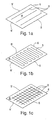
- the method according to the invention for producing a multilayer bellows seal includes a step of preparing a set of substantially rectangular and preferably planar metal sheets A on which at least one channel 3 is formed.
- said channels 3 may be substantially parallel to two sides of metal sheet A, as shown in fig. 1a, or they may form a serpentine, as shown in fig. 1b, or yet they may form a grid, as shown in fig. 1c.
- Said channels 3 are formed on at least one of the faces of metal sheet A and they may be obtained by different working techniques, depending on the material of sheet A: for instance, mechanical deformation, removal by means of a tool, removal by means of a laser, chemical corrosion, deposition of material on the whole of the metal sheet face except in correspondence of the desired channels, etc., can be used.
- metal spacers e. g., thin tubes or a grid
- metal sheet A could be applied to metal sheet A.
- the cross section of channels 3 can be chosen depending on the specific user's requirements: e.g. the cross section may be half-circular, as shown in Fig. 4, or rectangular or triangular.
- Fig. 2 shows the subsequent step of the method according to the invention applied to this first embodiment: here metal sheet A, after having been curved so as to form a hollow cylindrical body 1 and to cause the two major parallel sides to fit together, is welded along edges 5, 5'.
- channels 3 in the embodiment shown, lie on the inner face of said cylindrical body 1.
- a pair of metal cylindrical bodies 1, 1' which have been preferably obtained by the previous steps and at least one of which is provided with channels on one face, are placed inside one another, so that the face with the channels lies between the two cylinders, as clearly shown in Fig. 4.
- inner cylindrical body 1 will be slightly smaller than that of outer cylindrical body 1', and yet it will be such as to ensure the perfect adhesion of both cylindrical bodies by minimising volume 23 (here enlarged for sake of clarity of the description) provided between the faces of cylindrical bodies 1, 1'.
- the only interstices existing between said cylindrical bodies substantially consist of channels 3 initially formed on metal sheets A.
- Said channels 3 can be used as a conducting system, of which the overall volume will advantageously be extremely small.
- multilayer structure 11 thus obtained will be submitted to pot die forming to obtain a corrugated bellows structure, as shown in Fig. 3.
- cylindrical bodies 1, 1' Once cylindrical bodies 1, 1' have been deformed, they are sealed at their edges 6, 6' by means of a first ring insert 7 and a second disc insert 9, respectively, to which said cylindrical bodies 1, 1' are welded.
- volume 23 defined between the faces of said cylindrical bodies 1, 1' is hermetically isolated from the surrounding environment.
- outer and inner cylindrical bodies 1' and 1 are welded on lower edge 13 of ring 7, along line 15, and on inner edge 17 of ring 7, along line 19, respectively.
- inner cylindrical body 1 will be slightly longer than outer body 1'.
- Ring 7 has, on its inner surface, an annular groove 21, allowing channels 3 to communicate with a leak detecting system.
- lower edges 6' of outer and inner cylindrical bodies 1' and 1 are welded to cover 9 along line 25.
- both rings 7 could be provided with an annular groove 21.
- part of channels 3 could communicate with groove 21 of one ring 7, while the remaining channels communicate with the other ring 7.
- said ring 7 is further provided, in correspondence with groove 21, with a radial bore 27 putting said groove 21 in communication with a capillary 29 connected to a pressure detector 31 consisting of a deformable membrane capsule.
- said detector 31 is further connected, through a suitable duct 33, to a vacuum pump 35 allowing creating the desired vacuum conditions inside volume 23 confined between inner and outer cylindrical bodies 1 and 1'.
- said detector 31 is connected, through duct 33, to a pump 35 allowing pumping a fluid into said volume 23 between inner and outer cylindrical bodies 1 and 1', until attaining the desired pressure.
- volume 33 is pressurised, the adhesion between the different layers of multilayer structure 11 is maintained. Indeed the effect of the pressure, which would tend to separate said layers, is contrasted by the mechanical interference between the layers, related with the minimum diameter difference of cylindrical bodies 1, 1'.
- Fig. 6 shows a variant embodiment of the multilayer seal shown in Fig. 5, where said multilayer seal includes free layers.
- One or more cylindrical bodies 1" of intermediate diameters, each having channels on at least one face, are arranged between innermost cylindrical body 1 and outermost cylindrical body 1'.
- extreme cylindrical bodies 1, 1' may be made of a valuable, highly corrosion-resistant material
- intermediate cylindrical bodies 1" may be made of less valuable materials, simply having good elastic characteristics and tenacity, without need to cope with the problem of welding together materials of different nature.
- Fig. 7 shows the bellows seal when vacuum has been created in the volume between the layers. Depression detector 31 is disconnected from vacuum pump 35 and membrane 32 is flexed inwards because of the vacuum created between cylindrical bodies 1, 1', that is between the layers of the multilayer bellows seal.
- Duct 33 is hermetically sealed by a suitable seal 36 and vacuum pump 35 is removed.
- membrane 32 of pressure detector 31 is flexed outwards, and any loss of integrity of the bellows seal would be indicated by membrane 32 passing from the outwards flexed to the inwards flexed position.
- the overall volume of channels 3, which substantially form the only interstices between the seal layers, is extremely small and consequently the seal manufactured by the method described above is extremely responsive to fluid leaks, even of minimum amount.
- detector 31 will be very fast, contrary to the present seals that, as known, suffer from inertia in the response because of the time required to cause a detectable pressure change throughout the volume of the whole gap.
- channels 3 while they do not reduce the mechanical resistance of the seal, form a network of predetermined breaking points which make checks on the seal integrity easier.
- Fig. 8 shows an exemplary application of a bellows seal 37 manufactured by the method of the invention to a plug valve 39.
- valve 39 passes through chamber 41 containing bellows seal 37 by entering through inlet duct 43 and going out through outlet duct 45.
- Control stem 47 by acting onto cover 39, controls opening and closing of inlet duct 43.
- Bellows seal 27 is connected to pressure detector 31, which signals a loss of integrity of the seal, if any, and the consequent risk of fluid penetration into the seal.
- Figs. 9 and 10 refer to another embodiment of the invention, concerning manufacturing of a planar seal.
- Fig. 9 shows the starting step of the method of the invention, concerning channel formation.
- the method of the invention comprises preparing a set (usually a pair) of substantially disc-shaped and preferably planar metal sheets B, on which at least one channel 3 is formed.
- At least two metal sheets B which preferably have been obtained according to the previous steps and of which at least one has channels 3 on one face, are superimposed to form a multilayer structure, so that the face with the channels lies between the two sheets and said sheets are in close mutual contact.
- the seal can be submitted to pot die forming or similar working to impart it a profile with concentric corrugations.
- seal layers 101, 101' are welded at their circumferential edges to a ring 107, along lines 115 and 119.
- Said ring 107 has an annular groove 121, arranged to put channels 3 in communication with one another, and a radial bore 127 to put the volume confined between the layers in communication with a pressure detector 131 through a capillary 129.
- the last method step is connecting pressure detector 131 with a pump and bringing the pressure of the volume confined between the layers to a preset value.
- Fig. 10 shows the application of a multilayer planar seal thus obtained as a membrane 49 of a partition associated with a pressure gauge 57.
- Said partitions are used, for instance, along fluid distribution lines to protect measuring instruments, such as the pressure gauges, when the fluids flowing along said lines have such chemical-physical properties that they could damage said measuring instruments.
- pressure gauge 57 measures the pressure of the fluid flowing in pipe 51.
- a chamber 55 containing a multilayer membrane 49, is connected between said pressure gauge 57 and said pipe 51.
- Said membrane 49 divides said chamber 55 into a portion 55a, into which the fluid flowing in the pipe 51 penetrates when valve 53 is opened, and a portion 55b, containing the measurement fluid used by pressure gauge 57.
- the pressure in the volume confined between the layers of multilayer membrane 49 is brought to a preset value and said volume is connected to a pressure detector 31.
Landscapes
- Engineering & Computer Science (AREA)
- General Engineering & Computer Science (AREA)
- Mechanical Engineering (AREA)
- Gasket Seals (AREA)
- Laminated Bodies (AREA)
- Lining Or Joining Of Plastics Or The Like (AREA)
- Measuring Fluid Pressure (AREA)
Claims (30)
- Procédé de production d'un joint multicouches, comprenant les étapes consistant à :- préparer une pluralité de tôles essentiellement planes (A, B) ;- obtenir au moins un canal (3) sur au moins une face d'au moins l'une desdites tôles (A) ;- placer au moins une première et une seconde desdites tôles (A, B) en contact mutuel étroit de sorte que ladite (lesdites) face (s) dotée (s) dudit canal (3) dans ladite première tôle soit en face de ladite seconde tôle ;- fermer hermétiquement les bords (5, 5', 6, 6', 106) desdites première et seconde tôles de façon que le volume (23) confiné entre lesdites première et seconde tôles soit hermétiquement isolé de l'environnement extérieur ;- amener ledit volume isolé hermétiquement (23) à une valeur de pression préétablie.
- Procédé selon la revendication 1, dans lequel ledit volume (23) est connecté à un détecteur de pression (31, 131).
- Procédé selon la revendication 1, dans lequel une pluralité de canaux (3), disposés parallèlement l'un à l'autre ou suivant une relation en serpentin, en grille ou disposés radialement, est obtenue sur au moins une face d'au moins l'une desdites tôles (A).
- Procédé selon la revendication 1, dans lequel lesdites tôles (A) formant les couches (1, 1') du joint multicouches sont essentiellement des tôles métalliques rectangulaires.
- Procédé selon l'une quelconque des revendications précédentes, dans lequel après obtention desdits canaux (3), lesdites tôles sont soumises à une étape de configuration pour obtenir des corps cylindriques creux correspondants (1, 1'), et dans lequel lesdites tôles sont superposées en plaçant les cylindres obtenus (1, 1') l'un à l'intérieur de l'autre.
- Procédé selon la revendication 5, dans lequel ladite étape de configuration est obtenue au moyen d'un processus d'incurvation suivi d'une soudure le long de deux bords contigus (5, 5', 6, 6').
- Procédé selon la revendication 5 ou 6, dans lequel après ladite configuration, lesdits cylindres (1, 1') sont soumis à une étape de déformation pour obtenir un profil ondulé.
- Procédé selon la revendication 6, dans lequel lesdits bords (5, 5', 6, 6') sont fermés hermétiquement par soudure par l'intermédiaire de l'interposition d'une première et d'une seconde pièces d'insertion correspondantes (7, 9).
- Procédé selon la revendication 1, dans lequel lesdites tôles constituant les couches (1, 1') du joint multicouches sont des tôles métalliques configurées essentiellement en forme de disque (B).
- Procédé selon la revendication 9, dans lequel lesdits disques (101, 101') sont liés ensemble le long de leurs bordures circonférentielles (106) par soudure par l'intermédiaire de l'interposition d'une pièce d'insertion correspondante (127).
- Procédé selon la revendication 9 dans lequel après obtention desdits canaux (3), lesdits disques (101, 101') sont soumis à une étape de déformation pour obtenir un profil ondulé.
- Procédé selon la revendication 9 dans lequel ladite étape de déformation est obtenue par l'intermédiaire d'un processus de formage de profilés ou d'un processus de formage dans une matrice en pot.
- Procédé selon l'une quelconque des revendications précédentes dans lequel lesdits canaux (3) sont obtenus par déformation mécanique, technologie laser, corrosion chimique, dépôt de matériau ou application de pièces d'écartement sur la surface de ladite tôle.
- Procédé selon l'une quelconque des revendications précédentes dans lequel lesdits canaux présentent des configurations de section transversale semi-circulaire, rectangulaire ou triangulaire.
- Procédé selon l'une quelconque des revendications précédentes dans lequel ledit volume (23) est amené à une pression supérieure/inférieure à la pression extérieure au moyen d'un dispositif de compression/aspiration (35).
- Joint multicouches comprenant au moins une première couche et une seconde couche superposées, en contact mutuel étroit et fermé hermétiquement le long des bords (5, 5', 6, 6', 106) de façon à définir entre lesdites couches (1, 1', 101, 101') un volume correspondant (23), lequel est isolé hermétiquement de l'environnement voisin et dans lequel la pression est établie à une valeur préétablie, caractérisé en ce qu'au moins une face desdites couches (1, 1', 101, 101') faisant face audit volume (23) est dotée d'au moins un canal (3).
- Joint selon la revendication 16, dans lequel ledit joint comprend un détecteur de pression (31, 131) connecté avec ledit volume (23).
- Joint selon la revendication 16, dans lequel une pluralité de canaux (3), disposés parallèlement l'un à l'autre ou en serpentin ou en grille ou radialement, est obtenue sur au moins une face d'au moins l'une desdites couches (A).
- Joint selon la revendication 16, dans lequel lesdites couches sont des corps cylindriques creux (1, 1') de tôle métallique.
- Joint selon la revendication 19, dans lequel lesdits corps cylindriques creux (1, 1') sont fermés hermétiquement le long de leurs bords (5, 5', 6, 6') par soudure par l'intermédiaire de l'interposition d'une première pièce et d'une seconde pièce d'insertion correspondantes (7, 9).
- Joint selon la revendication 20, dans lequel ladite première pièce d'insertion est un anneau métallique (7), ledit cylindre intérieur (1, 1') et ledit cylindre extérieur (1, 1') étant soudés, respectivement, à la paroi intérieure et au bord inférieur dudit anneau métallique (7).
- Joint selon la revendication 20, dans lequel ladite seconde pièce d'insertion est un couvercle métallique (9), ledit cylindre intérieur (1, 1') et ledit cylindre extérieur (1, 1') étant soudés au bord latéral dudit couvercle métallique (9).
- Joint selon la revendication 16, dans lequel lesdites couches sont des éléments de tôle métallique configurés en disque (101, 101').
- Joint selon la revendication 23, dans lequel lesdits disques (101, 101') sont fermés hermétiquement le long de leurs bords par soudure par l'intermédiaire de l'interposition d'une pièce d'insertion métallique correspondante configurée en anneau (7, 9).
- Joint selon la revendication 21 ou 24, dans lequel ledit anneau (7, 107) présente, sur sa paroi interne, une gorge annulaire (21, 121) communiquant avec ledit canal (lesdits canaux) (3).
- Joint selon la revendication 25, dans lequel ladite gorge annulaire (7, 107) communique avec l'extérieur par un trou radial (27, 127) formé dans ledit anneau (7, 107).
- Joint selon la revendication 26, dans lequel ledit trou radial (27, 127) est connecté, à l'extérieur dudit anneau (7, 107), avec un capteur de pression (31, 131) à travers un capillaire (29, 129).
- Joint selon l'une quelconque des revendications 16 à 27, dans lequel ledit volume (23) est amené à une pression supérieure/inférieure à la pression externe.
- Joint selon l'une quelconque des revendications 16 à 28, dans lequel au moins une couche libre (1") est fournie dans ledit volume (23).
- Vanne destinée à des fluides, caractérisée en ce qu'elle comporte un joint multicouches selon l'une quelconque des revendications 16 à 22 ou 25 à 29.
Applications Claiming Priority (3)
| Application Number | Priority Date | Filing Date | Title |
|---|---|---|---|
| ITTO20020503 | 2002-06-14 | ||
| IT2002TO000503A ITTO20020503A1 (it) | 2002-06-14 | 2002-06-14 | Metodo per la produzione di una tenuta multistrato e tenuta multistrato cosi' ottenuta |
| PCT/IB2003/002267 WO2003106874A1 (fr) | 2002-06-14 | 2003-06-13 | Procede de production d'un joint multicouches et joint multicouches ainsi obtenu |
Publications (2)
| Publication Number | Publication Date |
|---|---|
| EP1546593A1 EP1546593A1 (fr) | 2005-06-29 |
| EP1546593B1 true EP1546593B1 (fr) | 2007-02-14 |
Family
ID=11459399
Family Applications (1)
| Application Number | Title | Priority Date | Filing Date |
|---|---|---|---|
| EP03730405A Expired - Lifetime EP1546593B1 (fr) | 2002-06-14 | 2003-06-13 | Procede de production d'un joint multicouches et joint multicouches ainsi obtenu |
Country Status (8)
| Country | Link |
|---|---|
| US (1) | US20050230924A1 (fr) |
| EP (1) | EP1546593B1 (fr) |
| CN (1) | CN1668868A (fr) |
| AT (1) | ATE354049T1 (fr) |
| AU (1) | AU2003241085A1 (fr) |
| DE (1) | DE60311842D1 (fr) |
| IT (1) | ITTO20020503A1 (fr) |
| WO (1) | WO2003106874A1 (fr) |
Families Citing this family (3)
| Publication number | Priority date | Publication date | Assignee | Title |
|---|---|---|---|---|
| US9541197B2 (en) * | 2011-06-01 | 2017-01-10 | General Electric Company | Seal system and method of manufacture |
| EP2864748B1 (fr) * | 2012-06-26 | 2018-10-03 | GE Oil & Gas UK Limited | Ensemble et test de joint |
| US10788148B2 (en) * | 2018-12-20 | 2020-09-29 | The Boeing Company | Conduits for transporting fluids |
Family Cites Families (16)
| Publication number | Priority date | Publication date | Assignee | Title |
|---|---|---|---|---|
| US2170015A (en) * | 1938-06-09 | 1939-08-22 | Ford Motor Co | Internal combustion engine |
| US2691773A (en) * | 1951-07-23 | 1954-10-12 | Harold V Lichtenberger | Valve leak detector |
| CH404321A (de) * | 1961-11-11 | 1965-12-15 | Rheinisches Metallwerk Gmbh | Rückflussverhinderndes Absperrventil |
| GB1039515A (en) * | 1962-07-24 | 1966-08-17 | Power Aux Ies Ltd | Improvements in or relating to flexible pressure tubes and ducts |
| US3472062A (en) * | 1967-09-13 | 1969-10-14 | Pathway Bellows Inc | Testable and pressurized multiple ply bellows |
| US3927818A (en) * | 1972-12-14 | 1975-12-23 | Chemetron Corp | Method of installing cylindrical bellows |
| US3831498A (en) * | 1973-04-26 | 1974-08-27 | Chemetron Corp | Multiple-ply bellows |
| DE3114620A1 (de) * | 1981-04-10 | 1982-10-28 | Interatom Internationale Atomreaktorbau Gmbh, 5060 Bergisch Gladbach | Mehrlagiger kompensator mit zwischen den lagen angeordneten abstandshaltern |
| US4511162A (en) * | 1983-02-02 | 1985-04-16 | Pathway Bellows, Inc. | Leak indicating conduit |
| JPS59232627A (ja) | 1983-06-16 | 1984-12-27 | Toshiba Corp | 多層ベロ−ズの製造方法 |
| US5072622A (en) * | 1990-06-04 | 1991-12-17 | Roach Max J | Pipeline monitoring and leak containment system and apparatus therefor |
| US6032960A (en) * | 1997-06-06 | 2000-03-07 | Wendl; Manfred | Multi-layered sealing element |
| ATE232944T1 (de) | 1998-03-25 | 2003-03-15 | Aseptomag Mts Ag | Prozessventil, insbesondere für die sterile verfahrenstechnik |
| US6220079B1 (en) * | 1998-07-22 | 2001-04-24 | Safety Liner Systems, L.L.C. | Annular fluid manipulation in lined tubular systems |
| US6634388B1 (en) * | 1998-07-22 | 2003-10-21 | Safetyliner Systems, Llc | Annular fluid manipulation in lined tubular systems |
| US6935376B1 (en) * | 1998-07-28 | 2005-08-30 | Safetyliner Systems, Llc | Enhancement of profiled tubular lining systems by channel augmentation |
-
2002
- 2002-06-14 IT IT2002TO000503A patent/ITTO20020503A1/it unknown
-
2003
- 2003-06-13 EP EP03730405A patent/EP1546593B1/fr not_active Expired - Lifetime
- 2003-06-13 AU AU2003241085A patent/AU2003241085A1/en not_active Abandoned
- 2003-06-13 DE DE60311842T patent/DE60311842D1/de not_active Expired - Lifetime
- 2003-06-13 CN CNA038168235A patent/CN1668868A/zh active Pending
- 2003-06-13 AT AT03730405T patent/ATE354049T1/de not_active IP Right Cessation
- 2003-06-13 WO PCT/IB2003/002267 patent/WO2003106874A1/fr not_active Ceased
- 2003-06-13 US US10/516,305 patent/US20050230924A1/en not_active Abandoned
Also Published As
| Publication number | Publication date |
|---|---|
| WO2003106874A1 (fr) | 2003-12-24 |
| CN1668868A (zh) | 2005-09-14 |
| ITTO20020503A1 (it) | 2003-12-15 |
| WO2003106874A8 (fr) | 2005-05-26 |
| US20050230924A1 (en) | 2005-10-20 |
| ITTO20020503A0 (it) | 2002-06-14 |
| AU2003241085A1 (en) | 2003-12-31 |
| DE60311842D1 (de) | 2007-03-29 |
| ATE354049T1 (de) | 2007-03-15 |
| EP1546593A1 (fr) | 2005-06-29 |
Similar Documents
| Publication | Publication Date | Title |
|---|---|---|
| US10794787B2 (en) | Diaphragm seal assembly with evacuated double diaphragm and vacuum monitoring | |
| CN102159859B (zh) | 用于密封可拆卸法兰接头的梳状双面叠加式垫片 | |
| CA2125552C (fr) | Rondelles de garniture, mode de fabrication connexe et dispositif d'etancheite muni de ces rondelles | |
| EP1373853B1 (fr) | Dispositif destine a sceller une bride de canalisation | |
| US4046010A (en) | Pressure transducer with welded tantalum diaphragm | |
| EP0899488A1 (fr) | Joint d'étanchéité résistant à une haute pression | |
| CN105203252A (zh) | 具有带类金刚石碳涂层的密封件的过程压力变送器 | |
| EP0899489B1 (fr) | Joint pour haute pression | |
| EP1546593B1 (fr) | Procede de production d'un joint multicouches et joint multicouches ainsi obtenu | |
| CN210511067U (zh) | 一种多层波纹管用的多级监测报警装置 | |
| EP0864078B1 (fr) | Garniture auto-active pour transmetteur de commande de processus | |
| ATE454615T1 (de) | Druckübertragungsvorrichtung mit vorausschauender korrosionsüberwachung | |
| JPH02501593A (ja) | フローティングダイヤフラム装置 | |
| EP2491364B1 (fr) | Membrane de séparation pour capteur de pression | |
| CN112964419B (zh) | 测量元件及包括该测量元件的测量装置 | |
| WO2003052239A1 (fr) | Disque de rupture articule avec ligne de coupe circulaire | |
| CN211740475U (zh) | 测量元件及包括该测量元件的测量装置 | |
| JP7090017B2 (ja) | ガスケット | |
| JP2002228003A (ja) | シール構造 | |
| US10591063B2 (en) | Spiral wound gasket | |
| JPH10132186A (ja) | U型金属ベローズ | |
| EP4649368A1 (fr) | Soupape de commande de fluide à géométrie de tension de diaphragme | |
| US20020140181A1 (en) | Reusable gasket | |
| JP7133349B2 (ja) | 枝付きガスケット | |
| CN118846682A (zh) | 一种双层滤芯结构、制备方法以及透气性检测方法 |
Legal Events
| Date | Code | Title | Description |
|---|---|---|---|
| PUAI | Public reference made under article 153(3) epc to a published international application that has entered the european phase |
Free format text: ORIGINAL CODE: 0009012 |
|
| 17P | Request for examination filed |
Effective date: 20050104 |
|
| AK | Designated contracting states |
Kind code of ref document: A1 Designated state(s): AT BE BG CH CY CZ DE DK EE ES FI FR GB GR HU IE IT LI LU MC NL PT RO SE SI SK TR |
|
| AX | Request for extension of the european patent |
Extension state: AL LT LV MK |
|
| DAX | Request for extension of the european patent (deleted) | ||
| GRAP | Despatch of communication of intention to grant a patent |
Free format text: ORIGINAL CODE: EPIDOSNIGR1 |
|
| GRAS | Grant fee paid |
Free format text: ORIGINAL CODE: EPIDOSNIGR3 |
|
| GRAA | (expected) grant |
Free format text: ORIGINAL CODE: 0009210 |
|
| AK | Designated contracting states |
Kind code of ref document: B1 Designated state(s): AT BE BG CH CY CZ DE DK EE ES FI FR GB GR HU IE IT LI LU MC NL PT RO SE SI SK TR |
|
| PG25 | Lapsed in a contracting state [announced via postgrant information from national office to epo] |
Ref country code: NL Free format text: LAPSE BECAUSE OF FAILURE TO SUBMIT A TRANSLATION OF THE DESCRIPTION OR TO PAY THE FEE WITHIN THE PRESCRIBED TIME-LIMIT Effective date: 20070214 Ref country code: BE Free format text: LAPSE BECAUSE OF FAILURE TO SUBMIT A TRANSLATION OF THE DESCRIPTION OR TO PAY THE FEE WITHIN THE PRESCRIBED TIME-LIMIT Effective date: 20070214 Ref country code: SI Free format text: LAPSE BECAUSE OF FAILURE TO SUBMIT A TRANSLATION OF THE DESCRIPTION OR TO PAY THE FEE WITHIN THE PRESCRIBED TIME-LIMIT Effective date: 20070214 Ref country code: FI Free format text: LAPSE BECAUSE OF FAILURE TO SUBMIT A TRANSLATION OF THE DESCRIPTION OR TO PAY THE FEE WITHIN THE PRESCRIBED TIME-LIMIT Effective date: 20070214 Ref country code: AT Free format text: LAPSE BECAUSE OF FAILURE TO SUBMIT A TRANSLATION OF THE DESCRIPTION OR TO PAY THE FEE WITHIN THE PRESCRIBED TIME-LIMIT Effective date: 20070214 Ref country code: CH Free format text: LAPSE BECAUSE OF FAILURE TO SUBMIT A TRANSLATION OF THE DESCRIPTION OR TO PAY THE FEE WITHIN THE PRESCRIBED TIME-LIMIT Effective date: 20070214 Ref country code: LI Free format text: LAPSE BECAUSE OF FAILURE TO SUBMIT A TRANSLATION OF THE DESCRIPTION OR TO PAY THE FEE WITHIN THE PRESCRIBED TIME-LIMIT Effective date: 20070214 Ref country code: DK Free format text: LAPSE BECAUSE OF FAILURE TO SUBMIT A TRANSLATION OF THE DESCRIPTION OR TO PAY THE FEE WITHIN THE PRESCRIBED TIME-LIMIT Effective date: 20070214 |
|
| REG | Reference to a national code |
Ref country code: GB Ref legal event code: FG4D |
|
| REG | Reference to a national code |
Ref country code: CH Ref legal event code: EP |
|
| REF | Corresponds to: |
Ref document number: 60311842 Country of ref document: DE Date of ref document: 20070329 Kind code of ref document: P |
|
| REG | Reference to a national code |
Ref country code: IE Ref legal event code: FG4D |
|
| PG25 | Lapsed in a contracting state [announced via postgrant information from national office to epo] |
Ref country code: SE Free format text: LAPSE BECAUSE OF FAILURE TO SUBMIT A TRANSLATION OF THE DESCRIPTION OR TO PAY THE FEE WITHIN THE PRESCRIBED TIME-LIMIT Effective date: 20070514 |
|
| PG25 | Lapsed in a contracting state [announced via postgrant information from national office to epo] |
Ref country code: BG Free format text: LAPSE BECAUSE OF EXPIRATION OF PROTECTION Effective date: 20070515 |
|
| PG25 | Lapsed in a contracting state [announced via postgrant information from national office to epo] |
Ref country code: ES Free format text: LAPSE BECAUSE OF FAILURE TO SUBMIT A TRANSLATION OF THE DESCRIPTION OR TO PAY THE FEE WITHIN THE PRESCRIBED TIME-LIMIT Effective date: 20070525 |
|
| PG25 | Lapsed in a contracting state [announced via postgrant information from national office to epo] |
Ref country code: PT Free format text: LAPSE BECAUSE OF FAILURE TO SUBMIT A TRANSLATION OF THE DESCRIPTION OR TO PAY THE FEE WITHIN THE PRESCRIBED TIME-LIMIT Effective date: 20070716 |
|
| NLV1 | Nl: lapsed or annulled due to failure to fulfill the requirements of art. 29p and 29m of the patents act | ||
| REG | Reference to a national code |
Ref country code: CH Ref legal event code: PL |
|
| EN | Fr: translation not filed | ||
| PG25 | Lapsed in a contracting state [announced via postgrant information from national office to epo] |
Ref country code: SK Free format text: LAPSE BECAUSE OF FAILURE TO SUBMIT A TRANSLATION OF THE DESCRIPTION OR TO PAY THE FEE WITHIN THE PRESCRIBED TIME-LIMIT Effective date: 20070214 |
|
| PLBE | No opposition filed within time limit |
Free format text: ORIGINAL CODE: 0009261 |
|
| STAA | Information on the status of an ep patent application or granted ep patent |
Free format text: STATUS: NO OPPOSITION FILED WITHIN TIME LIMIT |
|
| PG25 | Lapsed in a contracting state [announced via postgrant information from national office to epo] |
Ref country code: CZ Free format text: LAPSE BECAUSE OF FAILURE TO SUBMIT A TRANSLATION OF THE DESCRIPTION OR TO PAY THE FEE WITHIN THE PRESCRIBED TIME-LIMIT Effective date: 20070214 Ref country code: RO Free format text: LAPSE BECAUSE OF FAILURE TO SUBMIT A TRANSLATION OF THE DESCRIPTION OR TO PAY THE FEE WITHIN THE PRESCRIBED TIME-LIMIT Effective date: 20070214 |
|
| 26N | No opposition filed |
Effective date: 20071115 |
|
| PG25 | Lapsed in a contracting state [announced via postgrant information from national office to epo] |
Ref country code: MC Free format text: LAPSE BECAUSE OF NON-PAYMENT OF DUE FEES Effective date: 20070630 Ref country code: DE Free format text: LAPSE BECAUSE OF FAILURE TO SUBMIT A TRANSLATION OF THE DESCRIPTION OR TO PAY THE FEE WITHIN THE PRESCRIBED TIME-LIMIT Effective date: 20070515 |
|
| GBPC | Gb: european patent ceased through non-payment of renewal fee |
Effective date: 20070613 |
|
| PG25 | Lapsed in a contracting state [announced via postgrant information from national office to epo] |
Ref country code: IT Free format text: LAPSE BECAUSE OF FAILURE TO SUBMIT A TRANSLATION OF THE DESCRIPTION OR TO PAY THE FEE WITHIN THE PRESCRIBED TIME-LIMIT Effective date: 20070214 Ref country code: FR Free format text: LAPSE BECAUSE OF FAILURE TO SUBMIT A TRANSLATION OF THE DESCRIPTION OR TO PAY THE FEE WITHIN THE PRESCRIBED TIME-LIMIT Effective date: 20071005 Ref country code: GR Free format text: LAPSE BECAUSE OF FAILURE TO SUBMIT A TRANSLATION OF THE DESCRIPTION OR TO PAY THE FEE WITHIN THE PRESCRIBED TIME-LIMIT Effective date: 20070515 |
|
| PG25 | Lapsed in a contracting state [announced via postgrant information from national office to epo] |
Ref country code: GB Free format text: LAPSE BECAUSE OF NON-PAYMENT OF DUE FEES Effective date: 20070613 Ref country code: IE Free format text: LAPSE BECAUSE OF NON-PAYMENT OF DUE FEES Effective date: 20070613 |
|
| PG25 | Lapsed in a contracting state [announced via postgrant information from national office to epo] |
Ref country code: FR Free format text: LAPSE BECAUSE OF FAILURE TO SUBMIT A TRANSLATION OF THE DESCRIPTION OR TO PAY THE FEE WITHIN THE PRESCRIBED TIME-LIMIT Effective date: 20070214 |
|
| PG25 | Lapsed in a contracting state [announced via postgrant information from national office to epo] |
Ref country code: EE Free format text: LAPSE BECAUSE OF FAILURE TO SUBMIT A TRANSLATION OF THE DESCRIPTION OR TO PAY THE FEE WITHIN THE PRESCRIBED TIME-LIMIT Effective date: 20070214 |
|
| PG25 | Lapsed in a contracting state [announced via postgrant information from national office to epo] |
Ref country code: CY Free format text: LAPSE BECAUSE OF FAILURE TO SUBMIT A TRANSLATION OF THE DESCRIPTION OR TO PAY THE FEE WITHIN THE PRESCRIBED TIME-LIMIT Effective date: 20070214 |
|
| PG25 | Lapsed in a contracting state [announced via postgrant information from national office to epo] |
Ref country code: LU Free format text: LAPSE BECAUSE OF NON-PAYMENT OF DUE FEES Effective date: 20070613 |
|
| PG25 | Lapsed in a contracting state [announced via postgrant information from national office to epo] |
Ref country code: TR Free format text: LAPSE BECAUSE OF FAILURE TO SUBMIT A TRANSLATION OF THE DESCRIPTION OR TO PAY THE FEE WITHIN THE PRESCRIBED TIME-LIMIT Effective date: 20070214 Ref country code: HU Free format text: LAPSE BECAUSE OF FAILURE TO SUBMIT A TRANSLATION OF THE DESCRIPTION OR TO PAY THE FEE WITHIN THE PRESCRIBED TIME-LIMIT Effective date: 20070815 |