EP1546980B1 - Amelioration de la resolution et correction de l'inclinaison simultanees de diagraphies de resistivite au moyen d'une deconvolution non lineaire iterative - Google Patents
Amelioration de la resolution et correction de l'inclinaison simultanees de diagraphies de resistivite au moyen d'une deconvolution non lineaire iterative Download PDFInfo
- Publication number
- EP1546980B1 EP1546980B1 EP03759259.9A EP03759259A EP1546980B1 EP 1546980 B1 EP1546980 B1 EP 1546980B1 EP 03759259 A EP03759259 A EP 03759259A EP 1546980 B1 EP1546980 B1 EP 1546980B1
- Authority
- EP
- European Patent Office
- Prior art keywords
- log
- borehole
- formation model
- value
- logging
- Prior art date
- Legal status (The legal status is an assumption and is not a legal conclusion. Google has not performed a legal analysis and makes no representation as to the accuracy of the status listed.)
- Expired - Lifetime
Links
- 238000012937 correction Methods 0.000 title description 2
- 230000015572 biosynthetic process Effects 0.000 claims description 68
- 238000005755 formation reaction Methods 0.000 claims description 68
- 238000005259 measurement Methods 0.000 claims description 65
- 238000000034 method Methods 0.000 claims description 54
- 238000005553 drilling Methods 0.000 claims description 22
- 230000004044 response Effects 0.000 claims description 16
- 230000000694 effects Effects 0.000 claims description 15
- 238000012545 processing Methods 0.000 claims description 15
- 238000003860 storage Methods 0.000 claims description 12
- 230000007423 decrease Effects 0.000 claims 2
- 238000001914 filtration Methods 0.000 claims 1
- 230000008569 process Effects 0.000 description 9
- 230000006870 function Effects 0.000 description 5
- 238000004364 calculation method Methods 0.000 description 4
- 238000009499 grossing Methods 0.000 description 4
- 238000011835 investigation Methods 0.000 description 4
- 238000010586 diagram Methods 0.000 description 3
- 238000005481 NMR spectroscopy Methods 0.000 description 2
- 230000002708 enhancing effect Effects 0.000 description 2
- 239000012530 fluid Substances 0.000 description 2
- 230000001965 increasing effect Effects 0.000 description 2
- 230000006698 induction Effects 0.000 description 2
- 238000000691 measurement method Methods 0.000 description 2
- 238000012986 modification Methods 0.000 description 2
- 230000004048 modification Effects 0.000 description 2
- 239000003208 petroleum Substances 0.000 description 2
- 238000012360 testing method Methods 0.000 description 2
- 238000012935 Averaging Methods 0.000 description 1
- 238000004458 analytical method Methods 0.000 description 1
- 238000013459 approach Methods 0.000 description 1
- 238000004891 communication Methods 0.000 description 1
- 238000005094 computer simulation Methods 0.000 description 1
- 230000003750 conditioning effect Effects 0.000 description 1
- 230000008878 coupling Effects 0.000 description 1
- 230000001808 coupling effect Effects 0.000 description 1
- 238000010168 coupling process Methods 0.000 description 1
- 238000005859 coupling reaction Methods 0.000 description 1
- 230000003247 decreasing effect Effects 0.000 description 1
- 238000013461 design Methods 0.000 description 1
- 238000007598 dipping method Methods 0.000 description 1
- 229930195733 hydrocarbon Natural products 0.000 description 1
- 150000002430 hydrocarbons Chemical class 0.000 description 1
- 230000006872 improvement Effects 0.000 description 1
- 238000009434 installation Methods 0.000 description 1
- 238000004519 manufacturing process Methods 0.000 description 1
- 239000000463 material Substances 0.000 description 1
- 230000009022 nonlinear effect Effects 0.000 description 1
- 239000003129 oil well Substances 0.000 description 1
- 230000003287 optical effect Effects 0.000 description 1
- 230000035699 permeability Effects 0.000 description 1
- 230000005855 radiation Effects 0.000 description 1
- 239000000523 sample Substances 0.000 description 1
- 230000003068 static effect Effects 0.000 description 1
- 230000007704 transition Effects 0.000 description 1
- 239000013598 vector Substances 0.000 description 1
Images


Classifications
-
- G—PHYSICS
- G01—MEASURING; TESTING
- G01V—GEOPHYSICS; GRAVITATIONAL MEASUREMENTS; DETECTING MASSES OR OBJECTS; TAGS
- G01V3/00—Electric or magnetic prospecting or detecting; Measuring magnetic field characteristics of the earth, e.g. declination, deviation
- G01V3/38—Processing data, e.g. for analysis, for interpretation, for correction
Definitions
- Such information typically includes characteristics of the earth formations traversed by the wellbore, along with data relating to the size and configuration of the borehole itself.
- the collection of information relating to conditions downhole which commonly is referred to as "logging", can be performed by several methods.
- a probe or "sonde” housing formation sensors is lowered into the borehole after some or all of the well has been drilled, and is used to determine certain characteristics of the formations traversed by the borehole.
- the upper end of the sonde is attached to a conductive wireline that suspends the sonde in the borehole. Power is transmitted to the sensors and instrumentation in the sonde through the conductive wireline.
- the instrumentation in the sonde communicates information to the surface by electrical signals transmitted through the wireline. Since the sonde is in direct electrical contact with the surface installation, the communications delay is negligible. Accordingly, measurements can be made and communicated in "real time".
- a disadvantage of obtaining downhole measurements via wireline is that the drilling assembly must be removed or "tripped" from the drilled borehole before the desired borehole information can be obtained. This can be both time-consuming and extremely costly, especially in situations where a substantial portion of the well has been drilled. In this situation, thousands of feet of tubing may need to be removed and (if offshore) stacked on the platform. Typically, drilling rigs are rented by the day at a substantial cost. Consequently, the cost of drilling a well is directly proportional to the time required to complete the drilling process. Removing thousands of feet of tubing to insert a wireline logging tool can be an expensive proposition.
- a number of measurement techniques have been used in wireline and/or LWD measurements. These include, among others, induction, resistivity, permittivity, magnetic permeability, acoustic speed, nuclear magnetic resonance (NMR), gamma radiation (GR) and thermal neutron delay (TMD) measurement techniques.
- NMR nuclear magnetic resonance
- GR gamma radiation
- TMD thermal neutron delay
- Each tool has a "tool response" that extends over a measurement region, causing the tool to provide a measurement that represents a weighted average of material properties in that region. This averaging effect "smears" the property measurements, and creates the possibility that fine-resolution features (e.g., thin beds and sharp boundaries) maybe missed.
- Deconvolution Removal of the smearing effect is known as deconvolution or inversion.
- Deconvolution is known to be "an ill-posed problem" in that any number of formations could have produced the measured log. The presence of measurement nonlinearities further complicates the deconvolution problem.
- One or more parameters of the formation model are then adjusted based on this comparison of the estimated log to the actual log data, a new estimated log is calculated, a new comparison is made, and the process repeats.
- the forward deconvolution technique iteratively refines the formation model until the simulated log approximates the actual log.
- This technique can be computationally intensive, but may offer some advantages over other inversion approaches. Among these potential advantages are flexibility and stability in the presence of nonlinearities.
- a further method for evaluating the resistivity of invaded formations at high apparent dip angle is disclosed in U.S. Patent No. 6,047,240 .
- the existing inversion techniques have been found to yield inadequate resolution, in that thin beds are routinely overlooked. These thin beds may contain retrievable oil or other hydrocarbons. An inversion technique that offers improved resolution without instability would be desirable.
- the system comprises a data acquisition module, a storage module, and a processing module.
- the data acquisition module obtains logging data from measurements made by a sensor tool moving through a borehole, and stores the logging data in the storage module.
- the processing module accesses the storage module to retrieve and process the logging data to determine a formation model.
- the processing module iteratively updates a set of formation model values which correspond to a set of positions along the borehole. For each formation model value in the set, the iterative updating includes (i) calculating an error value; and (ii) applying a linearizing factor to the error value.
- the iterative updating is expressed as a weighted sum of a current formation model value with a product of the error value and the linearizing factor.
- the logging data is indicative of formation resistivity.
- the disclosed system may be applied to logging data from wireline operations and from logging while drilling operations. The updating of the formation model may continue until an adequate match between the logging data and a calculated tool response is achieved.
- FIG. 1 shows a well during wireline logging operations.
- a drilling platform 102 is equipped with a derrick 104 that supports a hoist 106. Drilling of oil and gas wells is commonly carried out by a string of drill pipes connected together so as to form a drilling string that is lowered through a rotary table 112 into a wellbore 114.
- the drilling string has been temporarily removed from the wellbore 114 to allow a sonde 116 to be lowered by wireline 118 into the wellbore 114.
- the sonde 116 is lowered to the bottom of the region of interest and subsequently pulled upward at a constant speed.
- the sonde 116 performs measurements on the formations 119 adjacent to the wellbore as they pass by.
- the measurement data is communicated to a logging facility 120 for storage, processing, and analysis.
- Logging facility 120 may be provided with electronic equipment for performing vertical resolution enhancement signal processing. Similar log data may be gathered and analyzed during drilling operations (Logging While Drilling, or LWD).
- the measurement data preferably includes resistivity measurements, conductivity measurements, or other measurements from which formation resistivity may be estimated.
- the measurement data preferably includes borehole survey information and/or relative dip measurements, i.e., measurements that indicate the angle at which the borehole intersects boundary planes between formation strata. Note that the relative dip angle may vary due to changes in formation bedding plane orientation and/or changes in borehole direction.
- Fig. 2 shows an illustrative functional block diagram of a system 200 for analyzing logging data.
- the system 200 may be contained within a logging facility 120, or alternatively, it may be an external system coupled to the logging facility. In yet another embodiment, it is an entirely separate system to which the logging data is transported.
- System 200 includes a module 202 which receives the log data.
- Module 202 may simply be a port through which the data enters the system, or it may be a more complex module for conditioning and acquiring data signals.
- the data is stored in a storage module 204, which maintains a copy of the data for access by the processing module 206.
- Storage module may take the form of dynamic random access memory (DRAM), static random access memory (SRAM), Flash ROM (read only memory), optical storage media, magnetic storage media, or any combination thereof. Note that storage module 204 (or a portion thereof) may be removable so as to be portable between systems. Storage module 204 may further maintain a copy of software for analyzing the data as described further below.
- Processing module 206 accepts instructions from a user via input module 208, and responsively operates on the data from storage module 204 to enhance log resolution.
- the measured log data and/or formation model may be displayed in some form to the user by display module 210.
- Resistivity logs are subject to nonlinear shoulder effects and nonlinear dip effects. Furthermore, there is a coupling between the two nonlinear effects.
- System 200 preferably provides a stable and efficient nonlinear deconvolution method which simultaneously accounts for both the shoulder and dipping effect. A preferred method embodiment is described below.
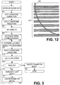
- Fig. 3 shows a flowchart diagram of a preferred method for deconvolving the measured log data.
- the preferred method may be implemented as software executed by system 200.
- the measured log data is obtained.
- the data may be in the form of resistivity (or equivalently, conductivity) measurements made at various positions distributed axially along the borehole. Relative dip measurements at axially distributed positions are preferably included too.
- the system 200 preferably adjusts the resistivity measurements to correct for the borehole effect.
- the measurements made by most resistivity tools are affected in a determinable way by the fluid in borehole around the tool.
- the properties of the fluid and the tool are known and can be combined to determine the adjustment for each measurement to compensate for the borehole effect.
- the output of this block is hereafter denoted M j , where j is an index that ranges over the measurement positions of interest in the borehole.
- the measurement positions of interest may be all actual measurement positions, equally-spaced (possibly interpolated) positions, or just selected positions.
- the measurement positions of interest may depend on any number of factors, and may vary between iterations. In the preferred embodiment, the measurement positions are equally spaced with a spacing somewhat smaller than the minimum spatial resolution of the tool. If resistivity measurements are unavailable for the selected measurement positions, they are preferably determined by interpolation between available measurements.
- the system 200 calculates log M j .
- the logarithmic transform may employ the natural logarithm or some other base, as desired.
- loop index i is initialized to zero.
- the initial formation model is determined in accordance with the inflection point method taught by Strickland in U.S. Patent No. 5,867,806 .
- the initial formation model is preferably chosen to be the measurements at the shallowest or next-to-shallowest depth of investigation.
- the system 200 calculates the expected resistivity measurements for the current formation model.
- model equations are available to calculate the response of the tool to any given formation. Often these equations are 1D (one dimensional) equations that accept formation resistivity as a function of axial position, accept relative dip as a function of axial position, and provide the expected tool measurements as a function of axial position along the borehole.
- more sophisticated model equations are sometimes available and may alternatively be employed.
- the output of this block is hereafter denoted as L j i , where i and j have their previously defined meanings.
- the system 200 calculates log L j i .
- This error measurement is indicative of how closely estimated measurements match the actual measurements.
- the system 200 performs a test to determine whether further loop iterations are desired.
- the test may include determining whether the error measurement is less than a predetermined threshold and/or determining whether a maximum number of iterations have already been performed.
- the fraction in equation (3) provides an approximate linearizing factor that appears to adequately compensate for the nonlinearities typically present in LWD resistivity logs.
- weighting factor values close to one are suitable as well, and may be preferred.
- ⁇ i is fixed at 0.9
- ⁇ i is fixed at 1.3.
- the weighting factors may be adjusted in accordance with additional experience so as to assure a good trade-off between fast convergence and stability.
- the method repeats, starting from block 310.
- the system smoothes the formation model in block 320.
- This smoothing may take the form of a Gaussian filter, although other smoothing filters may be used if desired. This smoothing serves to remove high frequency artifacts and noise that may appear in the updated formation model.
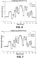
- Fig. 4 shows a graph of true formation resistivity (RT) vs. depth in a known formation. Superimposed on this graph are the 2 MHz phase resistivity log measurements taken at a shallow depth ("T1 2M raw"). The dip angle is zero. Also shown is the curve for the enhanced resistivity log ("T1 2M proc.") which is the smoothed formation model determined by applying the disclosed method to the T1 2M raw data. Note that the resistivity of the narrow beds is much closer to the true value.
- Fig. 5 shows a similar graph for the 2 MHz phase resistivity log measurements taken at a deep depth of investigation ("T5 2M raw").
- the initial formation model was set equal to the T1 2M raw curve.
- the results of the enhancement process are even more dramatic in this figure.
- Fig. 6 shows a similar graph for the 500 KHz phase resistivity log measurements taken at a shallow depth
- Fig. 7 shows the results for the 500 KHz phase resistivity log measurements taken at a deep depth of investigation. In all cases the enhancement process provides an improvement in the resolution.
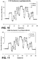
- Figs. 8-11 show graphs corresponding to Figs. 4-7 , but with a constant relative dip angle of 45°. Note that the enhancement process provides simultaneous compensation for both the shoulder effect and the dip effect.
- Fig. 12 shows an example of a curved borehole 402 passing through a set 404 of formation beds of gradually increasing thickness.
- the relative dip varies as a function of position in the borehole.
- the measurements of borehole orientation and hence, relative dip angle
- a continuous borehole path is preferably determined using a minimum curvature method.
- a detailed discussion of the minimum curvature method is provided in Bulletin on Directional Survey Calculation Method and Terminology, 1st ed., American Petroleum Institute, Dec. 31, 1985, p. 17 .
- Field survey data generally provides angle of inclination (borehole inclination), magnetic direction angle (borehole azimuth), and course length measurement (measured depth, recorded length of the drill string at a given point), as obtained from the multi-shot survey.
- angle of inclination borehole inclination
- magnetic direction angle borehole azimuth
- course length measurement measured depth, recorded length of the drill string at a given point
- smoothing is done by the use of a ratio factor which is defined by curvature (and dogleg) of the wellbore section. Given the borehole path, only the formation bedding angles are needed for the relative dip calculation. The formation bedding angles are usually determinable from seismic surveys or other sources.
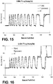
- Figs. 13-16 show graphs of true formation resistivity, simulated resistivity measurements, and enhanced resistivity, as a function of depth for this formation.
- Fig. 13 shows shallow 2 MHz measurements
- Fig. 14 shows deep 2 MHz measurements
- Fig. 15 shows shallow 500 KHz measurements
- Fig. 16 shows deep 500 Khz measurements. Note that the enhancement process performs well even in the presence of varying dip angles.
Landscapes
- Life Sciences & Earth Sciences (AREA)
- Engineering & Computer Science (AREA)
- Environmental & Geological Engineering (AREA)
- Geology (AREA)
- Remote Sensing (AREA)
- Physics & Mathematics (AREA)
- General Life Sciences & Earth Sciences (AREA)
- General Physics & Mathematics (AREA)
- Geophysics (AREA)
- Geophysics And Detection Of Objects (AREA)
- Numerical Control (AREA)
Claims (18)
- Procédé de traitement de journaux pour améliorer la résolution, dans lequel le procédé comprend : l'obtention d'un signal de mesure provenant d'un outil de capteur se déplaçant à travers un trou de forage, dans lequel les données qui indiquent la résistivité de la formation, et de préférence l'angle d'inclinaison, sont fournies par le signal de mesure ; et la mise à jour itérative d'un modèle de formation jusqu'à ce qu'une réponse d'outil calculée corresponde essentiellement au signal de mesure, dans lequel ladite mise à jour itérative comprend :le calcul d'une valeur d'erreur indiquant la mesure à laquelle la réponse d'outil calculée correspond au signal mesuré ;l'application d'un facteur de linéarisation à la valeur d'erreur ;la détermination d'un produit de la valeur d'erreur, du facteur de linéarisation et d'un facteur de pondération ; etla détermination d'un modèle de formation mis à jour à partir d'une somme de la valeur du modèle de formation actuelle pondérée et du produit déterminé.
- Procédé selon la revendication 1, comprenant également le filtrage du modèle de formation après ladite mise à jour itérative afin d'atténuer tout artefact à fréquence élevée.
- Procédé selon la revendication 1, dans lequel l'outil de capteur est l'un d'une sonde de diagraphie par câble ou d'un outil de diagraphie en cours de forage (LWD).
- Procédé selon la revendication 1, dans lequel la réponse d'outil calculée tient compte simultanément des effets des bancs en saillie et des angles d'inclinaison relatifs variables.
- Procédé selon la revendication 1, dans lequel les angles d'inclinaison relatifs sont déterminés au niveau de chaque point de mesure à l'aide d'un trajet de la courbure minimale du trou de forage.
- Procédé selon la revendication 1, dans lequel le facteur de pondération diminue au fur et à mesure de la réalisation d'itérations supplémentaires.
- Procédé selon la revendication 1, dans lequel la valeur d'erreur peut être exprimée sous forme de (log(Mj)-log(L i-1 j)), dans lequel Mj est une valeur des données de diagraphie corrigées du trou de forage, et Li-1 j est une valeur de la réponse d'outil calculée actuelle, dans lequel i représente le nombre d'itérations et dans lequel j est un indice qui recouvre la mesure des positions d'intérêt dans le trou de forage.
- Procédé selon la revendication 1 ou 7, dans lequel le facteur de linéarisation peut être exprimé sous forme de

- Système de caractérisation des formations entourant un trou de forage, le système comprenant :un module d'acquisition de données qui obtient des données de diagraphie, lesdites données de diagraphie sont générées à partir des mesures concernant la résistivité de la formation et de préférence l'angle d'inclinaison rapporté par un outil de capteur se déplaçant à travers le trou de forage ;un module de stockage conçu pour stocker les données de diagraphie ; etun module de traitement conçu pour réaliser des opérations sur les données de diagraphie pour déterminer un modèle de formation, dans lequel lesdites opérations comprennent la mise à jour itérative d'un ensemble de valeurs de modèle de formation qui correspond à un ensemble de positions le long du trou de forage, dans lequel pour chaque valeur de modèle de formation dans l'ensemble, ladite mise à jour itérative comprend :le calcul d'une valeur d'erreur indiquant la mesure à laquelle une réponse d'outil calculée correspond aux données de diagraphie ;l'application d'un facteur de linéarisation à la valeur d'erreur ;la détermination d'un produit de la valeur d'erreur, du facteur de linéarisation et d'un facteur de pondération ; etla détermination d'un modèle de formation mis à jour à partir d'une somme de la valeur du modèle de formation actuelle pondérée et du produit déterminé.
- Système selon la revendication 9, dans lequel le module de traitement met à jour l'ensemble des valeurs de modèle de formation jusqu'à ce qu'une réponse d'outil calculée corresponde aux données de diagraphie, assujetti à un nombre maximal d'itérations.
- Système selon la revendication 9, dans lequel le module de traitement est également conçu pour déterminer un modèle de formation initial avant de mettre à jour de façon itérative le modèle de formation, dans lequel le modèle de formation initial est défini comme étant égal aux données de diagraphie après correction des données de diagraphie pour tenir compte de l'effet du trou de forage.
- Système selon la revendication 9, dans lequel le module de traitement est également conçu pour filtrer l'ensemble des valeurs du modèle de formation après ladite mise à jour itérative afin d'atténuer tout artefact à fréquence élevée.
- Système selon la revendication 9, dans lequel l'outil de capteur est l'un d'une sonde de diagraphie par câble ou d'un outil de diagraphie en cours de forage (LWD).
- Système selon la revendication 10, dans lequel la réponse d'outil calculée tient compte simultanément des effets des bancs en saillie et des angles d'inclinaison relatifs variables.
- Système selon la revendication 9, dans lequel les angles d'inclinaison relatifs sont déterminés au niveau de chaque point de mesure à l'aide d'un trajet de la courbure minimale du trou de forage.
- Système selon la revendication 9, dans lequel le facteur de pondération diminue au fur et à mesure de la réalisation d'itérations supplémentaires.
- Système selon la revendication 9, dans lequel la valeur d'erreur peut être exprimée sous forme de (log (Mj )-log(Lj i-1), dans lequel Mj est une valeur des données de diagraphie corrigées du trou de forage, et Lj i-1 est une valeur de réponse d'outil calculée actuelle.
- Système selon la revendication 9 ou 17, dans lequel le facteur de linéarisation peut être exprimé sous forme de

Applications Claiming Priority (3)
| Application Number | Priority Date | Filing Date | Title |
|---|---|---|---|
| US251045 | 2002-09-20 | ||
| US10/251,045 US6885943B2 (en) | 2002-09-20 | 2002-09-20 | Simultaneous resolution enhancement and dip correction of resistivity logs through nonlinear iterative deconvolution |
| PCT/US2003/029082 WO2004027682A2 (fr) | 2002-09-20 | 2003-09-16 | Amelioration de la resolution et correction de l'inclinaison simultanees de diagraphies de resistivite au moyen d'une deconvolution non lineaire iterative |
Publications (3)
| Publication Number | Publication Date |
|---|---|
| EP1546980A2 EP1546980A2 (fr) | 2005-06-29 |
| EP1546980A4 EP1546980A4 (fr) | 2012-11-14 |
| EP1546980B1 true EP1546980B1 (fr) | 2017-12-27 |
Family
ID=31992639
Family Applications (1)
| Application Number | Title | Priority Date | Filing Date |
|---|---|---|---|
| EP03759259.9A Expired - Lifetime EP1546980B1 (fr) | 2002-09-20 | 2003-09-16 | Amelioration de la resolution et correction de l'inclinaison simultanees de diagraphies de resistivite au moyen d'une deconvolution non lineaire iterative |
Country Status (7)
| Country | Link |
|---|---|
| US (1) | US6885943B2 (fr) |
| EP (1) | EP1546980B1 (fr) |
| AU (1) | AU2003274990B2 (fr) |
| BR (1) | BRPI0314264B1 (fr) |
| CA (1) | CA2499272C (fr) |
| NO (1) | NO332599B1 (fr) |
| WO (1) | WO2004027682A2 (fr) |
Families Citing this family (57)
| Publication number | Priority date | Publication date | Assignee | Title |
|---|---|---|---|---|
| US6163155A (en) | 1999-01-28 | 2000-12-19 | Dresser Industries, Inc. | Electromagnetic wave resistivity tool having a tilted antenna for determining the horizontal and vertical resistivities and relative dip angle in anisotropic earth formations |
| US7659722B2 (en) | 1999-01-28 | 2010-02-09 | Halliburton Energy Services, Inc. | Method for azimuthal resistivity measurement and bed boundary detection |
| US8060310B2 (en) * | 2004-06-15 | 2011-11-15 | Baker Hughes Incorporated | Geosteering in earth formations using multicomponent induction measurements |
| US7274991B2 (en) * | 2004-06-15 | 2007-09-25 | Baker Hughes Incorporated | Geosteering in anisotropic formations using multicomponent induction measurements |
| US7392137B2 (en) * | 2004-06-15 | 2008-06-24 | Baker Hughes Incorporated | Determination of formation anistrophy, dip and azimuth |
| US8112227B2 (en) * | 2004-06-15 | 2012-02-07 | Baker Hughes Incorporated | Processing of multi-component induction measurements in a biaxially anisotropic formation |
| US7269515B2 (en) * | 2004-06-15 | 2007-09-11 | Baker Hughes Incorporated | Geosteering in anisotropic formations using multicomponent induction measurements |
| US7496451B2 (en) * | 2006-03-06 | 2009-02-24 | Baker Hughes Incorporated | Real time data quality control and determination of formation angles from multicomponent induction measurements using neural networks |
| CA2655200C (fr) | 2006-07-11 | 2013-12-03 | Halliburton Energy Services, Inc. | Ensemble d'outil modulaire de pilotage geologique de puits |
| MX2008014830A (es) * | 2006-07-12 | 2009-03-05 | Halliburton Energy Serv Inc | Metodo y aparato para construir una antena inclinada. |
| WO2008021868A2 (fr) * | 2006-08-08 | 2008-02-21 | Halliburton Energy Services, Inc. | Diagraphie de résistivité à artéfacts de pendage réduits |
| KR100837910B1 (ko) * | 2006-12-05 | 2008-06-13 | 현대자동차주식회사 | 액티브 헤드 레스트의 높이 유지 장치 |
| US8274289B2 (en) | 2006-12-15 | 2012-09-25 | Halliburton Energy Services, Inc. | Antenna coupling component measurement tool having rotating antenna configuration |
| AU2007345650C1 (en) * | 2007-01-29 | 2011-09-22 | Halliburton Energy Services, Inc. | Systems and methods having antennas for electromagnetic resistivity logging |
| AU2007349251B2 (en) * | 2007-03-16 | 2011-02-24 | Halliburton Energy Services, Inc. | Robust inversion systems and methods for azimuthally sensitive resistivity logging tools |
| WO2008118735A1 (fr) * | 2007-03-27 | 2008-10-02 | Halliburton Energy Services, Inc. | Systèmes et procédés pour afficher des données de journal |
| US8249812B2 (en) * | 2007-06-27 | 2012-08-21 | Schlumberger Technology Corporation | Characterizing an earth subterranean structure by iteratively performing inversion based on a function |
| US7756642B2 (en) | 2007-06-27 | 2010-07-13 | Schlumberger Technology Corporation | Characterizing an earth subterranean structure by iteratively performing inversion based on a function |
| WO2009075667A2 (fr) * | 2007-11-30 | 2009-06-18 | Halliburton Energy Services | Procédé et système pour prédire des performances d'un système de forage ayant de multiples structures de coupe |
| AU2008348131B2 (en) * | 2008-01-18 | 2011-08-04 | Halliburton Energy Services, Inc. | EM-guided drilling relative to an existing borehole |
| US8347985B2 (en) * | 2008-04-25 | 2013-01-08 | Halliburton Energy Services, Inc. | Mulitmodal geosteering systems and methods |
| BRPI0919556B8 (pt) | 2008-10-03 | 2019-07-30 | Halliburton Energy Services Inc | método, sistema para perfurar um poço, e, meio legível por computador |
| US10222507B2 (en) * | 2008-11-19 | 2019-03-05 | Halliburton Energy Services, Inc. | Data transmission systems and methods for azimuthally sensitive tools with multiple depths of investigation |
| US8957683B2 (en) | 2008-11-24 | 2015-02-17 | Halliburton Energy Services, Inc. | High frequency dielectric measurement tool |
| WO2010074678A2 (fr) | 2008-12-16 | 2010-07-01 | Halliburton Energy Services, Inc. | Procédés et systèmes de mesure de résistivité et de pilotage géologique azimutal au niveau du trépan |
| US8324895B2 (en) * | 2009-01-23 | 2012-12-04 | Baker Hughes Incorporated | MWD/LWD NMR imaging with long echo trains |
| US8780132B1 (en) * | 2009-03-21 | 2014-07-15 | Charles Saron Knobloch | Enhanced assimilation of orientation-dependent data in a multidimensional data volume |
| WO2011022012A1 (fr) | 2009-08-20 | 2011-02-24 | Halliburton Energy Services, Inc. | Caractérisation de fracture qui utilise des mesures de résistivité électromagnétiques directionnelles |
| MY177675A (en) | 2010-01-22 | 2020-09-23 | Halliburton Energy Services Inc | Method and apparatus for resistivity measurements |
| AU2011232848B2 (en) | 2010-03-31 | 2014-07-31 | Halliburton Energy Services, Inc. | Multi-step borehole correction scheme for multi-component induction tools |
| US8908471B2 (en) * | 2010-05-27 | 2014-12-09 | Pgs Geophysical As | Method for building velocity models for imaging in multi-azimuth marine seismic surveys |
| US9115569B2 (en) | 2010-06-22 | 2015-08-25 | Halliburton Energy Services, Inc. | Real-time casing detection using tilted and crossed antenna measurement |
| US8844648B2 (en) | 2010-06-22 | 2014-09-30 | Halliburton Energy Services, Inc. | System and method for EM ranging in oil-based mud |
| US8749243B2 (en) | 2010-06-22 | 2014-06-10 | Halliburton Energy Services, Inc. | Real time determination of casing location and distance with tilted antenna measurement |
| US8917094B2 (en) | 2010-06-22 | 2014-12-23 | Halliburton Energy Services, Inc. | Method and apparatus for detecting deep conductive pipe |
| CA2800148C (fr) | 2010-06-29 | 2015-06-23 | Halliburton Energy Services, Inc. | Procede et appareil pour detecter des anomalies souterraines allongees |
| US9360582B2 (en) | 2010-07-02 | 2016-06-07 | Halliburton Energy Services, Inc. | Correcting for magnetic interference in azimuthal tool measurements |
| BR112012028666A2 (pt) | 2010-07-16 | 2016-08-16 | Halliburton Energy Services Inc | sistema, e, método de perfilagem |
| AP2013006675A0 (en) * | 2010-07-27 | 2013-01-31 | Globaltech Corp Pty Ltd | Drilling activity logging device, system and method |
| GB201017814D0 (en) * | 2010-10-21 | 2010-12-01 | Zenith Oilfield Technology Ltd | A cable and method |
| GB201019567D0 (en) | 2010-11-19 | 2010-12-29 | Zenith Oilfield Technology Ltd | High temperature downhole gauge system |
| MY167753A (en) | 2011-04-18 | 2018-09-24 | Halliburton Energy Services Inc | Multicomponent borehole radar systems and methods |
| GB2495132B (en) | 2011-09-30 | 2016-06-15 | Zenith Oilfield Tech Ltd | Fluid determination in a well bore |
| US9014984B2 (en) * | 2011-10-14 | 2015-04-21 | Weatherford Technology Holdings, Llc | Resolution matched nonlinear resolution enhancement of well logs |
| BR112014009638A2 (pt) | 2011-10-31 | 2017-04-18 | Halliburton Energy Services Inc | método de perfilagem e sistema de perfilagem |
| GB2496863B (en) | 2011-11-22 | 2017-12-27 | Zenith Oilfield Tech Limited | Distributed two dimensional fluid sensor |
| EP2807507A4 (fr) * | 2012-01-23 | 2015-12-02 | Services Petroliers Schlumberger | Procédé de caractérisation de milieux anisotropes hétérogènes |
| WO2014003702A1 (fr) | 2012-06-25 | 2014-01-03 | Halliburton Energy Services, Inc. | Systèmes de diagraphie à antennes inclinées et procédés donnant des signaux de mesure robustes |
| GB2511739B (en) | 2013-03-11 | 2018-11-21 | Zenith Oilfield Tech Limited | Multi-component fluid determination in a well bore |
| CN105229492B (zh) | 2013-06-13 | 2019-08-16 | 哈里伯顿能源服务公司 | 随钻测井(lwd)转向可视化工具方法和系统 |
| WO2015099773A1 (fr) | 2013-12-27 | 2015-07-02 | Halliburton Energy Services, Inc. | Correction d'inclinaison dans des zones envahies |
| MX361243B (es) * | 2014-01-13 | 2018-11-30 | Halliburton Energy Services Inc | Corrección de inclinación utilizando resistividades de capa de formación estimadas. |
| US10365395B2 (en) | 2014-03-11 | 2019-07-30 | Halliburton Energy Services, Inc. | Multi-component induction logging systems and methods using blended-model inversion |
| US10295698B2 (en) | 2014-04-03 | 2019-05-21 | Halliburton Energy Services, Inc. | Multi-component induction logging systems and methods using selected frequency inversion |
| CN107109920A (zh) * | 2015-01-06 | 2017-08-29 | 哈利伯顿能源服务公司 | 构造特性确定设备、方法和系统 |
| DE112015005897T5 (de) * | 2015-01-07 | 2017-10-12 | Halliburton Energy Services, Inc. | Funktionale Erdmodellparametrierung zur Widerstandsinvertierung |
| WO2017127045A1 (fr) | 2016-01-19 | 2017-07-27 | Halliburton Energy Services, Inc. | Procédé de minimisation de réponse d'outil pour opérations de diagraphie de fond |
Family Cites Families (10)
| Publication number | Priority date | Publication date | Assignee | Title |
|---|---|---|---|---|
| US5210691A (en) * | 1990-05-08 | 1993-05-11 | Schlumberger Technology Corporation | Method and apparatus for producing a more accurate resistivity log from data recorded by an induction sonde in a borehole |
| US5184079A (en) * | 1990-11-13 | 1993-02-02 | Schlumberger Technology Corporation | Method and apparatus for correcting data developed from a well tool disposed at a dip angle in a wellbore to eliminate the effects of the dip angle on the data |
| US5862269A (en) * | 1994-11-23 | 1999-01-19 | Trustees Of Boston University | Apparatus and method for rapidly convergent parallel processed deconvolution |
| US5867806A (en) | 1996-03-13 | 1999-02-02 | Halliburton Energy Services, Inc. | System and method for performing inversion on LWD resistivity logs with enhanced resolution |
| US6047240A (en) * | 1998-01-16 | 2000-04-04 | Schlumberger Technology Corporation | Method and apparatus for evaluating the resistivity of invaded formations at high apparent dip angle |
| CA2355083C (fr) * | 1998-12-14 | 2005-01-11 | Halliburton Energy Services, Inc. | Conception d'un outil d'induction de faisceau haute resolution |
| US6304086B1 (en) | 1999-09-07 | 2001-10-16 | Schlumberger Technology Corporation | Method and apparatus for evaluating the resistivity of formations with high dip angles or high-contrast thin layers |
| US6502036B2 (en) * | 2000-09-29 | 2002-12-31 | Baker Hughes Incorporated | 2-D inversion of multi-component induction logging data to resolve anisotropic resistivity structure |
| US6643589B2 (en) * | 2001-03-08 | 2003-11-04 | Baker Hughes Incorporated | Simultaneous determination of formation angles and anisotropic resistivity using multi-component induction logging data |
| US6611762B1 (en) * | 2002-04-04 | 2003-08-26 | Halliburton Energy Services, Inc. | Method for determining parameters of earth formations surrounding a well bore |
-
2002
- 2002-09-20 US US10/251,045 patent/US6885943B2/en not_active Expired - Lifetime
-
2003
- 2003-09-16 WO PCT/US2003/029082 patent/WO2004027682A2/fr not_active Ceased
- 2003-09-16 AU AU2003274990A patent/AU2003274990B2/en not_active Ceased
- 2003-09-16 CA CA002499272A patent/CA2499272C/fr not_active Expired - Lifetime
- 2003-09-16 BR BRPI0314264A patent/BRPI0314264B1/pt not_active IP Right Cessation
- 2003-09-16 EP EP03759259.9A patent/EP1546980B1/fr not_active Expired - Lifetime
-
2005
- 2005-02-21 NO NO20050930A patent/NO332599B1/no not_active IP Right Cessation
Non-Patent Citations (1)
| Title |
|---|
| None * |
Also Published As
| Publication number | Publication date |
|---|---|
| CA2499272C (fr) | 2009-05-12 |
| BR0314264A (pt) | 2005-07-05 |
| WO2004027682A2 (fr) | 2004-04-01 |
| NO20050930D0 (no) | 2005-02-21 |
| EP1546980A4 (fr) | 2012-11-14 |
| NO332599B1 (no) | 2012-11-12 |
| AU2003274990A1 (en) | 2004-04-08 |
| BRPI0314264B1 (pt) | 2016-09-06 |
| US20040059513A1 (en) | 2004-03-25 |
| CA2499272A1 (fr) | 2004-04-01 |
| NO20050930L (no) | 2005-06-17 |
| EP1546980A2 (fr) | 2005-06-29 |
| AU2003274990B2 (en) | 2008-05-29 |
| WO2004027682A3 (fr) | 2004-05-06 |
| US6885943B2 (en) | 2005-04-26 |
Similar Documents
| Publication | Publication Date | Title |
|---|---|---|
| EP1546980B1 (fr) | Amelioration de la resolution et correction de l'inclinaison simultanees de diagraphies de resistivite au moyen d'une deconvolution non lineaire iterative | |
| US6810331B2 (en) | Fixed-depth of investigation log for multi-spacing multi-frequency LWD resistivity tools | |
| US8700372B2 (en) | Method for 3-D gravity forward modeling and inversion in the wavenumber domain | |
| EP1328832B1 (fr) | Procede servant a determiner les resistivites apparentes de reservoirs anisotropes | |
| US10429537B2 (en) | Efficiency of pixel-based inversion algorithms | |
| US10416336B2 (en) | Method of estimating anisotropic formation resistivity profile using a multi-component induction tool | |
| US10345475B2 (en) | Extended 1D inversion of electromagnetic measurements for formation evaluation | |
| US9422803B2 (en) | Passive magnetic ranging for SAGD and relief wells via a linearized trailing window kalman filter | |
| US10295698B2 (en) | Multi-component induction logging systems and methods using selected frequency inversion | |
| US6253155B1 (en) | Enhanced vertical resolution for logging tools using walsh-transform deconvolution | |
| US7269514B2 (en) | System and method for correcting induction logging device measurements by alternately estimating geometry and conductivity parameters | |
| US10914859B2 (en) | Real-time true resistivity estimation for logging-while-drilling tools | |
| US7043370B2 (en) | Real time processing of multicomponent induction tool data in highly deviated and horizontal wells | |
| CA3057232C (fr) | Systeme et procedes d'evaluation de formation au moyen de solutions pixelisees de donnees de formation | |
| US10365395B2 (en) | Multi-component induction logging systems and methods using blended-model inversion | |
| WO2018183223A1 (fr) | Procédés et systèmes permettant de déterminer des paramètres caractérisant des milieux poreux à partir de données collectées par une pluralité de différents instruments | |
| US7286937B2 (en) | Estimating formation properties from downhole data | |
| US20190086575A1 (en) | Real-Time Self-Consistency Quality Indicators for Multi-Component Induction Tools | |
| CN109236284B (zh) | 一种感应与侧向联测确定高陡地层真电阻率的方法 |
Legal Events
| Date | Code | Title | Description |
|---|---|---|---|
| PUAI | Public reference made under article 153(3) epc to a published international application that has entered the european phase |
Free format text: ORIGINAL CODE: 0009012 |
|
| 17P | Request for examination filed |
Effective date: 20050418 |
|
| AK | Designated contracting states |
Kind code of ref document: A2 Designated state(s): AT BE BG CH CY CZ DE DK EE ES FI FR GB GR HU IE IT LI LU MC NL PT RO SE SI SK TR |
|
| AX | Request for extension of the european patent |
Extension state: AL LT LV MK |
|
| DAX | Request for extension of the european patent (deleted) | ||
| RBV | Designated contracting states (corrected) |
Designated state(s): DE FR GB |
|
| A4 | Supplementary search report drawn up and despatched |
Effective date: 20121016 |
|
| RIC1 | Information provided on ipc code assigned before grant |
Ipc: G01V 3/38 20060101ALI20121010BHEP Ipc: G06F 19/00 20110101AFI20121010BHEP |
|
| 17Q | First examination report despatched |
Effective date: 20130129 |
|
| GRAP | Despatch of communication of intention to grant a patent |
Free format text: ORIGINAL CODE: EPIDOSNIGR1 |
|
| STAA | Information on the status of an ep patent application or granted ep patent |
Free format text: STATUS: GRANT OF PATENT IS INTENDED |
|
| INTG | Intention to grant announced |
Effective date: 20170809 |
|
| GRAS | Grant fee paid |
Free format text: ORIGINAL CODE: EPIDOSNIGR3 |
|
| GRAA | (expected) grant |
Free format text: ORIGINAL CODE: 0009210 |
|
| STAA | Information on the status of an ep patent application or granted ep patent |
Free format text: STATUS: THE PATENT HAS BEEN GRANTED |
|
| AK | Designated contracting states |
Kind code of ref document: B1 Designated state(s): DE FR GB |
|
| REG | Reference to a national code |
Ref country code: GB Ref legal event code: FG4D |
|
| REG | Reference to a national code |
Ref country code: DE Ref legal event code: R096 Ref document number: 60350878 Country of ref document: DE |
|
| REG | Reference to a national code |
Ref country code: FR Ref legal event code: PLFP Year of fee payment: 16 |
|
| REG | Reference to a national code |
Ref country code: DE Ref legal event code: R097 Ref document number: 60350878 Country of ref document: DE |
|
| PLBE | No opposition filed within time limit |
Free format text: ORIGINAL CODE: 0009261 |
|
| STAA | Information on the status of an ep patent application or granted ep patent |
Free format text: STATUS: NO OPPOSITION FILED WITHIN TIME LIMIT |
|
| REG | Reference to a national code |
Ref country code: DE Ref legal event code: R079 Ref document number: 60350878 Country of ref document: DE Free format text: PREVIOUS MAIN CLASS: G06F0019000000 Ipc: G16Z0099000000 |
|
| 26N | No opposition filed |
Effective date: 20180928 |
|
| PGFP | Annual fee paid to national office [announced via postgrant information from national office to epo] |
Ref country code: FR Payment date: 20190925 Year of fee payment: 17 Ref country code: DE Payment date: 20190918 Year of fee payment: 17 |
|
| REG | Reference to a national code |
Ref country code: DE Ref legal event code: R119 Ref document number: 60350878 Country of ref document: DE |
|
| PG25 | Lapsed in a contracting state [announced via postgrant information from national office to epo] |
Ref country code: FR Free format text: LAPSE BECAUSE OF NON-PAYMENT OF DUE FEES Effective date: 20200930 Ref country code: DE Free format text: LAPSE BECAUSE OF NON-PAYMENT OF DUE FEES Effective date: 20210401 |
|
| PGFP | Annual fee paid to national office [announced via postgrant information from national office to epo] |
Ref country code: GB Payment date: 20220705 Year of fee payment: 20 |
|
| REG | Reference to a national code |
Ref country code: GB Ref legal event code: PE20 Expiry date: 20230915 |
|
| PG25 | Lapsed in a contracting state [announced via postgrant information from national office to epo] |
Ref country code: GB Free format text: LAPSE BECAUSE OF EXPIRATION OF PROTECTION Effective date: 20230915 |