EP1547501A1 - Friteuse - Google Patents
Friteuse Download PDFInfo
- Publication number
- EP1547501A1 EP1547501A1 EP03795330A EP03795330A EP1547501A1 EP 1547501 A1 EP1547501 A1 EP 1547501A1 EP 03795330 A EP03795330 A EP 03795330A EP 03795330 A EP03795330 A EP 03795330A EP 1547501 A1 EP1547501 A1 EP 1547501A1
- Authority
- EP
- European Patent Office
- Prior art keywords
- oil
- storage tank
- food
- tank
- oil storage
- Prior art date
- Legal status (The legal status is an assumption and is not a legal conclusion. Google has not performed a legal analysis and makes no representation as to the accuracy of the status listed.)
- Withdrawn
Links
Images



Classifications
-
- A—HUMAN NECESSITIES
- A47—FURNITURE; DOMESTIC ARTICLES OR APPLIANCES; COFFEE MILLS; SPICE MILLS; SUCTION CLEANERS IN GENERAL
- A47J—KITCHEN EQUIPMENT; COFFEE MILLS; SPICE MILLS; APPARATUS FOR MAKING BEVERAGES
- A47J37/00—Baking; Roasting; Grilling; Frying
- A47J37/12—Deep fat fryers, e.g. for frying fish or chips
- A47J37/1276—Constructional details
- A47J37/1285—Valves or arrangements to drain used oil or food particles settled at the bottom of the frying vessel
-
- A—HUMAN NECESSITIES
- A47—FURNITURE; DOMESTIC ARTICLES OR APPLIANCES; COFFEE MILLS; SPICE MILLS; SUCTION CLEANERS IN GENERAL
- A47J—KITCHEN EQUIPMENT; COFFEE MILLS; SPICE MILLS; APPARATUS FOR MAKING BEVERAGES
- A47J37/00—Baking; Roasting; Grilling; Frying
- A47J37/12—Deep fat fryers, e.g. for frying fish or chips
- A47J37/1271—Accessories
-
- A—HUMAN NECESSITIES
- A47—FURNITURE; DOMESTIC ARTICLES OR APPLIANCES; COFFEE MILLS; SPICE MILLS; SUCTION CLEANERS IN GENERAL
- A47J—KITCHEN EQUIPMENT; COFFEE MILLS; SPICE MILLS; APPARATUS FOR MAKING BEVERAGES
- A47J37/00—Baking; Roasting; Grilling; Frying
- A47J37/12—Deep fat fryers, e.g. for frying fish or chips
- A47J37/1276—Constructional details
- A47J37/129—Frying vessels
Definitions
- This invention relates to a food fryer having a frying food tank which comprises a water layer area (a water tank area) and an oil layer area (an oil tank area) there on, in which bits of fried batter are coming down to the water layer area through the oil layer area, especially having an oil storage tank formed at a predetermined position of the water layer area.
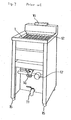
- Fig. 7 shows an external view structure of a conventional food fryer
- Fig.8 shows a sectional view of an oil layer area and a water layer area in the conventional food fryer: 1 is the oil layer area for storing food frying oil; 2 is the water layer area; 3 is a heat source such as a heating burner; 4 is an air cooling tube formed by a means such as welding on the outer wall of the oil layer area 1; 10 is bits of fried batter; 11 is a water discharge cock; 12 is a net; 14 is an oil discharge cock; 15 is an adjusting wheel or a roller for adjusting a balance of the food fryer on a floor surface; 16 is an air outlet; 17 is a thermostat for controlling the heat source 3.
- 1 is the oil layer area for storing food frying oil
- 2 is the water layer area
- 3 is a heat source such as a heating burner
- 4 is an air cooling tube formed by a means such as welding on the outer wall of the oil layer area 1
- 10 is bits of fried batter
- oil and water in the food fryer are respectively separated into the oil layer area 1 and the water layer area 2 due to the difference in specific gravity thereof, where the oil is heated by the heat source 3 to fry meat, fish, vegetables, etc.
- the cooling means such as the air cooling tube 4 provided below the heat source 3 insulates thermal conduction caused through the heated oil at a high temperature and by bits of fried batter settled down in the water during frying work so as to control oxidation of the oil and an increase of the water temperature, furthermore to avoid steam bubbles on the oil surface, which may bring difficulties in frying operation.
- the temperature of the oil therein is usually heated up about 200 ⁇ during the frying operation. And we must hence cool down the oil prior to cleaning the food fryer after the frying work. Furthermore, it is necessary to store the oil in a separate container and then to put it back to the food fryer, if the same oil is to be used repeatedly. In this way, it is not easy to handle the conventional food fryer.
- a preparation step in the above US Patent for cleaning the oil layer area and the water layer area out the oil storage tank of the food fryer is explained hereafter as one example. It is optional whether water is to be put into the oil storage tank prior to frying anything or not: in this example the oil storage tank of the food fryer is filled with water by user's operation of closing the lower cock and simultaneously opening the upper cock, and closing the upper cock thereafter.
- the preparation steps for cleaning are as follows.
- the oil storage tank contains the oil, with both the upper cock and the lower cock closed; the oil layer area and the water layer area except the oil storage tank are in empty and these areas are in space coupled to outside of the food fryer through the water discharge cock; thereby capable of cleaning both the layers outside the oil storage tank.
- the water discharge cock is to be closed and the upper cock of the oil storage tank is to be opened, where the oil in the oil storage would flow out by merely pouring water into the food fryer due to a difference in gravity between oil and water. This state is just ready for another food frying work.
- the food fryer disclosed in US Patent No. 5,632,266 is good in use for improving the efficiency of the food frying operation.
- this food fryer has room for further improvement in product cost, assembling labor and handling performance of it because the oil storage tank comprises two cocks, the upper cock and the lower clock.
- the object according to the invention is to reduce the cost and the labor for making the food fryer, and to improve frying and cleaning work by using an oil storage tank with an opening instead of the conventional upper cock, where an upper part of the opening is over its lower part and a lower cock of the oil storage tank is formed same as conventional.
- the food fryer of this invention has the oil storage tank provided with the opening for inflow and outflow of the oil, and with the lower cock for draining out water in the storage tank and filling it with used-oil at the previous frying work, the upper part of which opening overhangs its lower part.
- the oil storage tank may be made in any shape such as a cylinder-like, a cubic-like, a cube-like, a sphere-like or a rugby ball-like (an ellipse in section) of vertically or horizontally long.
- the inside of the oil storage tank is always coupled to inner space of the frying food tank through the opening. When the lower cock of the oil storage tank is opened, the inside of the oil storage tank is also coupled to the outside of the fryer.
- the opening may be formed on any upper place of the oil storage tank, preferably on the upper side wall.
- the water in the oil storage is out drained through the lower cock, following which the oil heated at a high temperature flows into the oil storage tank from the oil layer area through the opening. After a certain time, closing the lower cock allows the oil storage tank to be filled with the used oil. And the water discharge cock of the water layer area is opened.
- this invention is effective in that number of components, assembling work thereof and factory expenses of the food fryer are respectively reduced, and in that the cleaning work next to the frying work in the food fryer is easy to be done.
- Any kind of energy may be used for the heat source 3 such as electricity, gas and so on.
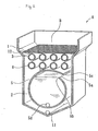
- the food fryer A has the cylindrical oil storage tank 5, where the opening 5a is formed at the upper side wall thereof so that oil in the oil layer area 1 moves through the opening 5a to be stored therein, if required.
- the opening 5a is arranged around a boundary between the water layer area 2 and the oil layer area 1, and formed in a shape that the upper end 5c is extended outside of the oil storage tank 5 than the lower end 5b so as to cover this end 5b.
- the upper end 5c of the opening 5 is extended out of the opening 5a so as to over the lower end 5b and is formed at the side wall, not top wall, of the oil storage tank 5, and hence cleaning water and so on for the cleaning scarcely pours into the oil storage tank 5 during the cleaning work,
- the oil in the oil storage tank 5 may be taken to outer space of the feed fryer by opening the cock 5d.
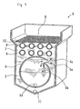
- the oil storage tank 5 is provided in state of contacting with outside air at the wall of the food fryer C, it is easy to efficiently cool the oil storage tank 5 after storing the used oil therein, and hence the cleaning work for the frying food tank D is to be started in short time after the frying food tank D being emptied.
- the oil in the oil layer area 1 may be also taken out by opening the oil discharge cock 14 in the state that the oil is not stored in the oil storage tank 5 as shown in Fig.4.
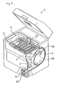
- the food fryer E of Fig.5 is made in compact as a whole for household use, where electric heater 3' is used as heat source of oil and no air cooling tube in the oil layer area 1 is provided.
- Other basic composition of the food fryer C is the same as that of the food fryer A shown in Fig.1.
- the electric heater 3' is repeatedly arranged in a longitudinal direction of the frying food tank F in continuous state, by contrast, it may be repeatedly arranged in a lateral direction or other any direction.
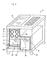
- the food fryer G of Fig.6 comprises the rectangular parallelepiped oil storage tank 6, which is formed below and in parallel with the food frying tank H and is connected thereto through the opening 6a formed on upper side wall.
- the upper end 6c of the opening 6a extended out from the oil storage tank 6 so as to cover the lower end 6b thereof.
- the food frying tank H is to be cleaned in the same way as in case of the food fryer A of Fig.1:
- the upper end 6c of the opening 6 is extended out of the opening 6a so as to over the lower end 6b and is formed at the side wall of the oil storage tank 6, and hence cleaning water and so on for the cleaning scarcely pours into the oil storage tank 5 during the cleaning work.
- oil in the oil storage tank 6 may be taken to outer space by opening the cock 6d.
- Water inlet opening of each the food fryer A, C, E and G is not shown in figures but may be formed at any place of the oil layer area 1.
- the air cooling tube 4 may be eliminated in also the food fryer A and G.
- Each of the food fryers A, C, E and G has no cock for opening and closing the opening 5a, 6a, the production cost is reduced and the cleaning work may be simply easy to be done.
- the food fryer according to the invention is intended to give safety and efficiency in the cleaning work thereof and to reduce product cost, food fryer which is good for both business use and household use.
Landscapes
- Engineering & Computer Science (AREA)
- Food Science & Technology (AREA)
- Frying-Pans Or Fryers (AREA)
Applications Claiming Priority (3)
| Application Number | Priority Date | Filing Date | Title |
|---|---|---|---|
| JP2002263817 | 2002-09-10 | ||
| JP2002263817 | 2002-09-10 | ||
| PCT/JP2003/011499 WO2004023955A1 (fr) | 2002-09-10 | 2003-09-09 | Friteuse |
Publications (2)
| Publication Number | Publication Date |
|---|---|
| EP1547501A1 true EP1547501A1 (fr) | 2005-06-29 |
| EP1547501A4 EP1547501A4 (fr) | 2007-05-09 |
Family
ID=31986471
Family Applications (1)
| Application Number | Title | Priority Date | Filing Date |
|---|---|---|---|
| EP03795330A Withdrawn EP1547501A4 (fr) | 2002-09-10 | 2003-09-09 | Friteuse |
Country Status (8)
| Country | Link |
|---|---|
| US (1) | US7231918B2 (fr) |
| EP (1) | EP1547501A4 (fr) |
| JP (1) | JP3964433B2 (fr) |
| KR (1) | KR100954902B1 (fr) |
| CN (1) | CN100399969C (fr) |
| AU (1) | AU2003264398A1 (fr) |
| BR (1) | BR0314168A (fr) |
| WO (1) | WO2004023955A1 (fr) |
Families Citing this family (8)
| Publication number | Priority date | Publication date | Assignee | Title |
|---|---|---|---|---|
| US8953148B2 (en) * | 2005-12-28 | 2015-02-10 | Nikon Corporation | Exposure apparatus and making method thereof |
| KR101323565B1 (ko) | 2006-01-19 | 2013-10-29 | 가부시키가이샤 니콘 | 이동체 구동 방법 및 이동체 구동 시스템, 패턴 형성 방법및 패턴 형성 장치, 노광 방법 및 노광 장치, 그리고디바이스 제조 방법 |
| WO2007102484A1 (fr) | 2006-03-07 | 2007-09-13 | Nikon Corporation | procédé de fabrication de dispositif, système DE FABRICATION DE DISPOSITIF, ET instrument de mesure/d'examen |
| KR101517131B1 (ko) * | 2013-11-25 | 2015-05-06 | (주)메타사이언스 | 유수조 튀김 장치 |
| KR101741311B1 (ko) * | 2015-04-07 | 2017-05-30 | 조상훈 | 수유식 튀김기 |
| US10736463B2 (en) * | 2016-03-17 | 2020-08-11 | Henny Penny Corporation | Multiport/rotary valve sensor using hall effect control |
| KR20190070031A (ko) | 2017-12-12 | 2019-06-20 | 주식회사 에스파이어텍 | 유수 분리식 전기 튀김 장치 |
| KR102024060B1 (ko) | 2017-12-12 | 2019-09-24 | 주식회사 에스파이어텍 | 유수 분리식 가스 튀김 장치 |
Family Cites Families (7)
| Publication number | Priority date | Publication date | Assignee | Title |
|---|---|---|---|---|
| JPS60139222A (ja) * | 1983-12-28 | 1985-07-24 | リコ−機器株式会社 | フライヤ− |
| CN2090164U (zh) * | 1990-05-05 | 1991-12-11 | 邢济利 | 节油油炸食品槽 |
| CN2121898U (zh) * | 1992-03-08 | 1992-11-18 | 邢济利 | 食品油炸槽 |
| CN1058384C (zh) | 1994-05-17 | 2000-11-15 | 佐藤忠羲 | 油炸食品用的器具 |
| KR100309040B1 (ko) * | 1999-04-09 | 2001-09-29 | 송영주 | 튀김기의 수분 공급장치 |
| JP3487583B2 (ja) * | 2000-01-27 | 2004-01-19 | 株式会社大喜商会 | 油浄化装置 |
| KR100387739B1 (ko) * | 2001-03-07 | 2003-06-18 | 송영주 | 튀김기 |
-
2003
- 2003-09-09 KR KR1020057004019A patent/KR100954902B1/ko not_active Expired - Fee Related
- 2003-09-09 WO PCT/JP2003/011499 patent/WO2004023955A1/fr not_active Ceased
- 2003-09-09 EP EP03795330A patent/EP1547501A4/fr not_active Withdrawn
- 2003-09-09 AU AU2003264398A patent/AU2003264398A1/en not_active Abandoned
- 2003-09-09 JP JP2004535912A patent/JP3964433B2/ja not_active Expired - Fee Related
- 2003-09-09 US US10/524,862 patent/US7231918B2/en not_active Expired - Lifetime
- 2003-09-09 BR BR0314168-3A patent/BR0314168A/pt not_active Application Discontinuation
- 2003-09-09 CN CNB038215144A patent/CN100399969C/zh not_active Expired - Fee Related
Also Published As
| Publication number | Publication date |
|---|---|
| US7231918B2 (en) | 2007-06-19 |
| JPWO2004023955A1 (ja) | 2006-01-05 |
| JP3964433B2 (ja) | 2007-08-22 |
| BR0314168A (pt) | 2005-07-19 |
| EP1547501A4 (fr) | 2007-05-09 |
| CN100399969C (zh) | 2008-07-09 |
| KR20050042492A (ko) | 2005-05-09 |
| KR100954902B1 (ko) | 2010-04-27 |
| AU2003264398A1 (en) | 2004-04-30 |
| US20050252506A1 (en) | 2005-11-17 |
| CN1681426A (zh) | 2005-10-12 |
| WO2004023955A1 (fr) | 2004-03-25 |
Similar Documents
| Publication | Publication Date | Title |
|---|---|---|
| US5632266A (en) | Fryer | |
| US7231918B2 (en) | Food fryer | |
| US7208702B2 (en) | Steam cooker | |
| CN104930707B (zh) | 热水器水箱、热水器及其清洗控制方法 | |
| KR20150109873A (ko) | 분리형 수유식 튀김기 | |
| JP4170287B2 (ja) | 食材茹で機 | |
| JP3595850B2 (ja) | 揚げ物器 | |
| KR200440640Y1 (ko) | 튀김기 | |
| EP1747742B1 (fr) | Appareil de préparation de boisson | |
| JP2013085736A (ja) | 麺茹で装置 | |
| JP2002291623A (ja) | 油揚げ器 | |
| CN110353511A (zh) | 沥水组件及具有沥水组件的烹饪器具 | |
| KR101538769B1 (ko) | 분리형 수유식 튀김기 | |
| JP2009072379A (ja) | 冷凍麺調理装置 | |
| KR20120111517A (ko) | 수유식 튀김장치 | |
| CN219913685U (zh) | 液体冷却装置及冷却杯 | |
| US20140373731A1 (en) | Cooking device | |
| JP2007054603A (ja) | 飲料作成器 | |
| KR20130117535A (ko) | 유수분리형 튀김기 | |
| JP7357339B2 (ja) | 廃油回収容器および廃油回収方法 | |
| JPH0741005B2 (ja) | 流体加熱装置 | |
| JPH0937947A (ja) | コーヒー抽出器 | |
| JPS6215204B2 (fr) | ||
| GB1604427A (en) | Expansion boilers | |
| JPH0231995B2 (fr) |
Legal Events
| Date | Code | Title | Description |
|---|---|---|---|
| PUAI | Public reference made under article 153(3) epc to a published international application that has entered the european phase |
Free format text: ORIGINAL CODE: 0009012 |
|
| 17P | Request for examination filed |
Effective date: 20050407 |
|
| AK | Designated contracting states |
Kind code of ref document: A1 Designated state(s): AT BE BG CH CY CZ DE DK EE ES FI FR GB GR HU IE IT LI LU MC NL PT RO SE SI SK TR |
|
| AX | Request for extension of the european patent |
Extension state: AL LT LV MK |
|
| DAX | Request for extension of the european patent (deleted) | ||
| A4 | Supplementary search report drawn up and despatched |
Effective date: 20070405 |
|
| STAA | Information on the status of an ep patent application or granted ep patent |
Free format text: STATUS: THE APPLICATION IS DEEMED TO BE WITHDRAWN |
|
| 18D | Application deemed to be withdrawn |
Effective date: 20070403 |