EP1547536A1 - Cathéter à ballonet, appareil médical et procédé de traitement d'un organe vivant - Google Patents
Cathéter à ballonet, appareil médical et procédé de traitement d'un organe vivant Download PDFInfo
- Publication number
- EP1547536A1 EP1547536A1 EP20040102453 EP04102453A EP1547536A1 EP 1547536 A1 EP1547536 A1 EP 1547536A1 EP 20040102453 EP20040102453 EP 20040102453 EP 04102453 A EP04102453 A EP 04102453A EP 1547536 A1 EP1547536 A1 EP 1547536A1
- Authority
- EP
- European Patent Office
- Prior art keywords
- balloon
- fluid
- temperature
- catheter shaft
- seconds
- Prior art date
- Legal status (The legal status is an assumption and is not a legal conclusion. Google has not performed a legal analysis and makes no representation as to the accuracy of the status listed.)
- Granted
Links
Images

Classifications
-
- A—HUMAN NECESSITIES
- A61—MEDICAL OR VETERINARY SCIENCE; HYGIENE
- A61M—DEVICES FOR INTRODUCING MEDIA INTO, OR ONTO, THE BODY; DEVICES FOR TRANSDUCING BODY MEDIA OR FOR TAKING MEDIA FROM THE BODY; DEVICES FOR PRODUCING OR ENDING SLEEP OR STUPOR
- A61M25/00—Catheters; Hollow probes
- A61M25/10—Balloon catheters
-
- A—HUMAN NECESSITIES
- A61—MEDICAL OR VETERINARY SCIENCE; HYGIENE
- A61B—DIAGNOSIS; SURGERY; IDENTIFICATION
- A61B18/00—Surgical instruments, devices or methods for transferring non-mechanical forms of energy to or from the body
- A61B18/04—Surgical instruments, devices or methods for transferring non-mechanical forms of energy to or from the body by heating
-
- A—HUMAN NECESSITIES
- A61—MEDICAL OR VETERINARY SCIENCE; HYGIENE
- A61B—DIAGNOSIS; SURGERY; IDENTIFICATION
- A61B17/00—Surgical instruments, devices or methods
- A61B17/22—Implements for squeezing-off ulcers or the like on inner organs of the body; Implements for scraping-out cavities of body organs, e.g. bones; for invasive removal or destruction of calculus using mechanical vibrations; for removing obstructions in blood vessels, not otherwise provided for
- A61B17/22031—Gripping instruments, e.g. forceps, for removing or smashing calculi
- A61B17/22032—Gripping instruments, e.g. forceps, for removing or smashing calculi having inflatable gripping elements
-
- A—HUMAN NECESSITIES
- A61—MEDICAL OR VETERINARY SCIENCE; HYGIENE
- A61B—DIAGNOSIS; SURGERY; IDENTIFICATION
- A61B17/00—Surgical instruments, devices or methods
- A61B17/22—Implements for squeezing-off ulcers or the like on inner organs of the body; Implements for scraping-out cavities of body organs, e.g. bones; for invasive removal or destruction of calculus using mechanical vibrations; for removing obstructions in blood vessels, not otherwise provided for
- A61B2017/22001—Angioplasty, e.g. PCTA
- A61B2017/22002—Angioplasty, e.g. PCTA preventing restenosis
-
- A—HUMAN NECESSITIES
- A61—MEDICAL OR VETERINARY SCIENCE; HYGIENE
- A61B—DIAGNOSIS; SURGERY; IDENTIFICATION
- A61B18/00—Surgical instruments, devices or methods for transferring non-mechanical forms of energy to or from the body
- A61B2018/00005—Cooling or heating of the probe or tissue immediately surrounding the probe
- A61B2018/00011—Cooling or heating of the probe or tissue immediately surrounding the probe with fluids
- A61B2018/00023—Cooling or heating of the probe or tissue immediately surrounding the probe with fluids closed, i.e. without wound contact by the fluid
-
- A—HUMAN NECESSITIES
- A61—MEDICAL OR VETERINARY SCIENCE; HYGIENE
- A61B—DIAGNOSIS; SURGERY; IDENTIFICATION
- A61B18/00—Surgical instruments, devices or methods for transferring non-mechanical forms of energy to or from the body
- A61B2018/00053—Mechanical features of the instrument of device
- A61B2018/00214—Expandable means emitting energy, e.g. by elements carried thereon
- A61B2018/0022—Balloons
-
- A—HUMAN NECESSITIES
- A61—MEDICAL OR VETERINARY SCIENCE; HYGIENE
- A61B—DIAGNOSIS; SURGERY; IDENTIFICATION
- A61B18/00—Surgical instruments, devices or methods for transferring non-mechanical forms of energy to or from the body
- A61B18/04—Surgical instruments, devices or methods for transferring non-mechanical forms of energy to or from the body by heating
- A61B2018/044—Surgical instruments, devices or methods for transferring non-mechanical forms of energy to or from the body by heating the surgical action being effected by a circulating hot fluid
- A61B2018/046—Surgical instruments, devices or methods for transferring non-mechanical forms of energy to or from the body by heating the surgical action being effected by a circulating hot fluid in liquid form
Definitions
- the present invention relates to a balloon catheter, a medical apparatus, a method for treating a living organ and a use of the medical apparatus for treating a living organ. More particularly, the present invention relates to a balloon catheter which can cure a diseased tissue by heating and cooling a living organ in a very short time and, in particular, can expand a blood vessel without causing damages when the balloon catheter is used in the percutanuous transluminal coronary angioplasty, a medical apparatus comprising the balloon catheter, a method for treating a living organ using the balloon catheter and a use of the medical apparatus for treating a living organ.
- PTCA percutanuous transluminal coronary angioplasty
- examples of the operation in which PTCA was applied and the diseases to which PTCA could be applied were rather limited. Due to the progress in instruments and technology, the application of this technology has been expanded not only to multivessel diseases but also to complete occlusion and acute myocardial infarction. However, the frequency of recurrence of stenosis is great, and this is considered to be the greatest problem of PTCA. To prevent the recurrence of stenosis, various stents have been developed and used.
- a blood vessel is forced to expand by a pressure as great as 800 to 1,000 kPa in the ordinary PTCA, the tissue is torn or the tissue of the blood vessel is degraded by the great force. Therefore, the recurrence of stenosis tends to take place due to excessive growth of the cells of the smooth muscle during the restoration of the coronary artery.
- the present invention has an object of providing a balloon catheter, a medical apparatus, a method for treating a living organ and a use of the medical apparatus for treating a living organ which can heat and cool the living organ within a very short time to cure a diseased tissue and expand a blood vessel without damages, in particular, in application to the percutanuous transluminal coronary angioplasty.
- the present invention provides:
- the balloon catheter of the present invention comprises a proximally disposed connecting member comprising an inlet for a fluid, an outlet for a fluid and an inlet for energy, a balloon, a catheter shaft comprising a lumen for introducing the fluid into the balloon and a lumen for discharging the fluid from the balloon and a heat-generating member.
- the proximally disposed connecting member and a proximal portion of the catheter shaft are connected to each other, a distal portion of the catheter shaft and a proximal portion of the balloon is connected to each other, and the heat-generating member is in contact with the fluid at the inside of the balloon or in a distal portion of the catheter shaft.
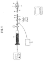
- FIG. 1 shows a diagram exhibiting an embodiment of the balloon catheter of the present invention.
- the balloon catheter of the present embodiment comprises a proximally disposed connecting member 1 comprising an inlet for a fluid, an outlet for a fluid and an inlet for energy, a balloon 8, a catheter shaft 6 through which a lumen 2 for introducing the fluid into the balloon and a lumen 3 for discharging the fluid from the balloon, an optical fiber 4 for introducing laser beams and a lead wire to a temperature sensor 5 are inserted, and a heat-generating member 7.
- An apparatus for introducing a fluid 9 and a apparatus emitting laser beams 10 are disposed at proximal positions.
- a temperature sensor 11 is disposed at the inside of the balloon.
- This catheter is inserted into a living organ so that the balloon reaches the portion of disease.
- the balloon is expanded by introducing a fluid into the balloon.
- Laser beams are emitted, and the energy of the laser beams is converted into heat by the heat-generating member.
- the temperature of the surface of the balloon is raised to a prescribed temperature by the obtained heat in a short time.
- the emission of the laser beams is stopped, and the surface of the balloon is cooled in a short time with a fluid at the room temperature. In this manner, the tubular organ can be expanded without causing damages to the living organ.
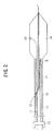
- FIG. 2 shows a diagram exhibiting another embodiment of the balloon catheter of the present invention.
- the balloon catheter of the present embodiment comprises a proximally disposed connecting member 12 comprising an inlet for a fluid, an outlet for a fluid and an inlet for energy, a balloon 19, a catheter shaft 17 through which a lumen 13 for introducing the fluid into the balloon and a lumen 14 for discharging the fluid from the balloon, an optical fiber 15 for introducing laser beams and a lead wire to a temperature sensor 16 are inserted, and a heat-generating member 18.
- a temperature sensor 20 is disposed at the inside of the balloon.
- the shapes of the lumen for introducing the fluid into the balloon and the lumen for discharging the fluid from the balloon are not particularly limited. Two tubes may be used separately as the two lumens. As another shape, the inside of a single tube having a circular sectional shape may be separated into two portions with an inner wall extending in the longitudinal direction, and the formed two portions may be used as the two lumens. In combination with the lumens for the fluid, for example, a lead wire for passing a high frequency electric current as the energy and a lumen for inserting a thermocouple for the measurement of the temperature may be inserted.
- the proximally disposed connecting member and a proximal portion of the catheter shaft are connected to each other, and a distal portion of the catheter shaft and a proximal portion of the balloon is connected to each other.
- the heat-generating member 7 is in contact with the fluid at the inside of the balloon 8.
- the heat-generating member 18 is in contact with the fluid introduced into the balloon 19 at a position in a distal portion of the catheter shaft 17.
- the method for bringing the heat-generating member into contact with the fluid introduced into the balloon is not particularly limited.
- the heat-generating member may be disposed at the inside of the lumen for introducing a fluid into the balloon in a distal portion of the catheter shaft, or a portion of the lumen for introducing a fluid into the balloon at a distal portion of the catheter shaft may be formed into the heat-generating member.
- the heat-generating member may also be disposed at the outside of the discharging end of the lumen for introducing a fluid into the balloon in a distal portion of the catheter shaft.
- the heat-generating member 7 as the device for converting the energy of laser beams is disposed at the inside of the balloon.
- the polymer at a portion at the discharging end of the lumen for introducing a fluid into the balloon is removed, and the exposed metal braid works as the heat-generating member 18 of the device for converting the energy of laser beams.
- the heat-generating member is present at the inside of the balloon or in a distal portion of the catheter shaft in the balloon catheter of the present invention, the fluid is heated at the inside of the balloon or immediately before being introduced into the balloon, and the temperature of the balloon can be accurately controlled with stability.
- the form of the balloon catheter of the present invention is not particularly limited.
- the form may be a form of the monorail type having a guide wire lumen between the distal portion of the balloon and a guide wire port open at an intermediate portion of the catheter shaft, or a form of the over-the-wire type having a guide wire lumen inserted through the entire length of the catheter.
- the energy supplied to the heat-generating member is not particularly limited.
- the energy include high frequency electric current of about 500 Hz and laser beams.
- a heat-generating material such as a wire of a Ni-Cr alloy, a heat-generating material containing carbon and tungsten can be used as the heat-generating member.
- a metal member absorbing the laser beams and converting the beams into heat such as stainless steel, chromium steel, ferrite steel and a nickel/titanium ultraelastic alloy can be used as the heat-generating member.
- thermosetting resin having a great heat resistance
- a thermosetting resin As the material of the balloon, damages caused by the contact of the heat-generating member and the balloon with each other can be prevented.
- a thermoplastic resin can be used as the material of the balloon since there is no possibility that the heat-generating member and the balloon are in contact with each other.
- the thermoplastic resin can be formed into a thin film with more excellent productivity than the thermosetting resin, and the balloon can be produced economically in accordance with the blow molding or the like process.
- thermoplastic resin Since a thin film of the thermoplastic resin has a small modulus, the properties for folding, re-wrapping and insertion into a body cavity are excellent, and the folded balloon deforms delicately to follow the curved shape of the body cavity and can be inserted with a small resistance.
- heat is transferred to the fluid through the contact of the heat-generating member with the fluid at the inside of the catheter or in the distal portion of the catheter shaft.
- the over-all heat transfer coefficient is great, and the fluid can be heated efficiently. Since the fluid is heated to the prescribed temperature at the inside of the balloon or is introduced into the balloon immediately after being heated to the prescribed temperature, the entire portions at the surface and at the inside of the balloon can be kept at the same temperature.
- the balloon catheter of the present invention when the heat-generating member is in contact with the fluid in the distal portion of the catheter shaft, it is preferable that the balloon comprises a thermoplastic resin and is produced in accordance with the blow molding process.
- thermoplastic resins having no crosslinking at all but also thermoplastic resins having partial crosslinking can be used as the thermoplastic resin as long as the thermoplastic resin can be molded in accordance with the extrusion molding process or the blow molding process.
- thermoplastic resin used in the present invention examples include polyolefin resins, polyamide resin, polyamide elastomers, polyether amide resins, polyester resins, polyester elastomers, fluororesins, polyurethane resins, silicone resins, natural rubber and synthetic rubbers.
- the process for producing the balloon comprising the thermoplastic resin in accordance with the blow molding is not particularly limited.
- the balloon can be obtained by cutting a tube obtained from the thermoplastic resin in accordance with the extrusion molding process to form a parison, followed by blow molding the obtained parison with biaxial stretching.
- the stretching ratio in the blow molding with biaxial stretching is not particularly limited. It is preferable that the stretching ratio is in the range of 1.5 to 5 in the longitudinal direction and in the range of 2 to 5 in the radial direction, and more preferably in the range of 2 to 4 in the longitudinal direction and in the range of 2.5 to 4 in the radial direction.
- the temperature of the blow molding to prepare the balloon is 100°C or higher, more preferably 105°C or higher and most preferable 110°C or higher. Since a physiological saline or a contrast medium for X-ray using water as the solvent or the dispersion medium is used as the medium for heating the balloon in almost all cases, the temperature of the balloon does not exceed 100°C in almost all cases. Therefore, when the blow molding to prepare the balloon is conducted at a temperature exceeding 100°C, the balloon can be used safely with little possibility of deformation by heating during the used of the balloon catheter.
- the balloon produced in accordance with the so-called cold blowing process at a temperature of about 40 to 80°C tends to show a decrease in the diameter of the balloon due to the reversion of the shape when the balloon is heated at a temperature higher than that of the blow molding although the strength relative to the thickness is great due to the orientation of the polymer with crystallization.
- the balloon prepared in accordance with the blow molding process at a high temperature can be used with excellent stability under heating although the blow molding process at a high temperature has heretofore been considered to cause insufficient strength.
- the entire catheter shaft or the distal portion of the catheter shaft where the heat-generating member is disposed comprises a heat-resistant material.
- the heat-resistant material include Ni-Ti ultraelastic alloys, stainless steel, polyimides, polyether imides, polysulfones, polyether ether ketones and composite materials comprising these materials. Since these materials have a suitable flexibility in combination with the heat resistance, the catheter shaft exhibiting an excellent balance can be obtained.
- the medical apparatus of the present invention comprises a balloon catheter described above and a temperature sensor disposed at the inside of the balloon or at the catheter shaft at a distal position from the heat-generating member.
- the fluid at a low temperature is introduced from the inlet for a fluid, flows through the inside of the balloon and is discharged from the outlet for a fluid.
- Energy is introduced from the inlet for energy into the catheter shaft, is converted into heat by the heat-generating member and heats the fluid.
- a living organ is heated and cooled for a medical treatment by the balloon which is heated and cooled, respectively, with the fluid.
- the medical apparatus of the present invention can heat the fluid efficiently and raise the temperature of the balloon in a short time since heat is transferred from the heat-generating member disposed at the inside of the balloon or in the distal portion of the catheter shaft to the fluid introduced into the balloon in the field of flow.
- the temperature of the balloon can be accurately controlled by sending the signal detected by the temperature sensor to the apparatus for output of the energy and controlling the amount of the introduced energy. Since the heat-generating member is disposed at the inside of the balloon or in the distal portion of the catheter shaft, the fluid at a low temperature flows through the inside of the balloon immediately after stopping the introduction of the energy, and the temperature of the balloon can be lowered in a short time.
- a living organ is constituted with proteins containing collagen as the main component, and proteins are softened at higher temperatures similarly to ordinary polymers.
- the effect of heat to living cells is relatively mild with respect to the time. Necrosis of cells takes place when the cells are kept at a high temperature for a long time. Change in the physical properties of collagen in tissues of blood vessels is a physicochemical phenomenon and takes place instantaneously. Therefore, by heating a living tissue rapidly in a short time, very thin surface layers of the living tissue alone can be heated to kill the tissue or to provide the apoptosis factor without causing biological damages to deeper portions.
- the tubular cavity for obtaining sufficient blood stream is secured without causing damages to the tissue due to excessive forces, and the stable opening of the tubular cavity can be achieved by the sufficient blood stream after the treatment.
- the medical apparatus of the present invention has the ability of heating the balloon from 35 ⁇ 40°C to 60 ⁇ 80°C within 30 seconds and cooling from the temperature attained by the heating to a temperature of 45°C or lower within 40 seconds.
- the medical treatment can be conducted without causing great invasion to the living organ.
- the medical apparatus of the present invention comprises a means for detecting the pressure
- the balloon can be expanded by applying a pressure with adjustment of the degrees of opening of the inlet for a fluid and the outlet for a fluid or the pressure of the introduced fluid.
- the medical apparatus of the present invention uses laser beams as the energy.
- Laser beams show quick responses, and a great output can be obtained using a small apparatus.
- the tip portion of the optical fiber for introduction of the laser beams may have a cone shape or a round shape having the diameter gradually decreasing towards the tip.
- the tip portion of the optical fiber may have a rough surface.
- Figure 3 shows a side view of a cone shape of the tip portion of an optical fiber having the diameter gradually decreasing towards the tip. Due to the cone shape, the round shape or the rough surface of the tip portion 21 of the optical fiber, the temperature at the inside of the balloon can be maintained uniformly. It is preferable that the tip portion of the optical fiber has, among these shapes, a cone shape having a diameter gradually decreasing towards the tip.
- the medical apparatus of the present invention can be used for method for treating the diseases in which it is desirable to heat very thin surface layer of the living tissue of the portion of disease.
- Using the medical apparatus of the present invention it is possible for example, to make the very thin surface layers of the living tissue of the portion of disease alone to die by heating the tissue rapidly in a short time or to provide the apoptosis factor without causing biological damages to deeper portions. It is particularly useful for the method of treating stenosis in a living organ.
- the tubular cavity for obtaining sufficient blood stream is secured without causing damages to the tissue due to excessive forces, and the stable opening of the tubular cavity can be achieved by the sufficient blood stream after the treatment.
- the catheter In applying the medical apparatus of the present invention to a patient in need of such treatment for treating a living organ, the catheter is inserted into a living organ so that the balloon of the catheter reaches the portion of disease and the fluid at low temperature is introduced into the balloon and energy is introduced to the heat-generating member during a period of time to effect the portion of disease is heated to a temperature level which is effective for the treatment of the portion of disease.
- the level of the temperature at which the portion of disease is heated and the period of time during which the energy is introduced to the heat-generating member are not particularly limited. They are determined so that the effect of heating the potion of disease is effective for the treatment but not excessive resulting in the damage of living organ.
- the energy is cut off and the portion of disease is cooled quickly by the fluid at lower temperature flowing into the balloon to the temperature level at which the living organ is not damaged.
- the balloon is expanded by applying a pressure to an appropriate level.
- a portion of disease of the living organ is heated from 35 ⁇ 40°C to 60 ⁇ 80°C within 30 seconds, expanded by applying a pressure of 500 kPa or smaller to the balloon and cooled from the temperature attained by the heating to a temperature of 45°C or lower within 40 seconds.
- the order of heating the portion of disease and expanding the balloon by application of a pressure is not particularly limited.
- the temperature may be raised after a pressure of 500 kPa or smaller is applied to the balloon. In this case, when the pressure of 500 kPa or smaller is applied to the balloon, the expansion of the living organ does not take place at temperatures around the room temperature, but takes place when the temperature reaches 60 to 80°C.
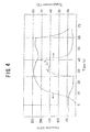
- Figure 4 shows a diagram exhibiting the changes in the pressure at the inside of the balloon and the temperature at the surface of the balloon with time.
- the pressure at the inside of the balloon begins to be raised and reaches 200 kPa after 14 seconds.
- the pressure at the inside of the balloon reaches 240 kPa 25 seconds after the start of the introduction of the fluid, the emission of the laser beams is started.
- the temperature of the balloon at the surface is rapidly raised and reaches 60°C 4 seconds after the start of the emission of the laser beams.
- the emission of laser beams is controlled by switching on and off the apparatus based on the signal transferred from the temperature sensor in a manner such that the temperature at the surface of the balloon is kept in the range of 60 to 70°C.
- the balloon When the emission of the laser beams is stopped 15 seconds after the start of the emission of the laser beams, the balloon is rapidly cooled with the fluid, and the temperature at the surface of the balloon is lowered to 45°C 3 seconds after the stopping of the emission of the laser beams.
- the introduction of the fluid is stopped 20 seconds after the stopping of the emission of the laser beams, and the pressure at the inside of the balloon is lowered.
- the time required to raise the temperature from 35 ⁇ 40°C to 60 ⁇ 80°C exceeds 30 seconds, there is the possibility that the thickness of the living organ decreases due to damages, and the stenosis takes place with passage of time.
- the temperature at the portion of disease of the living organ is lower than 60°C, there is the possibility that the expansion is insufficient under a pressure of the balloon of 500 kPa or smaller.
- the pressure of the balloon exceeds 500 kPa, there is the possibility that the tissue of the living organ is torn or degraded.
- the time of lowering the temperature to 45°C or lower exceeds 40 seconds, there is the possibility that the thickness of the living organ decreases due to damages, and the stenosis takes place with passage of time.
- the method of treating a living organ of the present invention can be advantageously applied to medical treatments of portions of disease of a blood vessel such as the percutanuous transluminal coronary angioplasty (PTCA).
- PTCA percutanuous transluminal coronary angioplasty
- the tissue of the inner skin is not stabilized even when the tissue is formed, and this is considered to cause the recurrence of the stenosis.
- the surface of the tissue of the blood vessel alone is heated instantaneously.
- the tissue of the tubular cavity is expanded by application of a small pressure without causing damages in deeper portions of the tubular cavity, and the tissue of the blood vessel is treated safely and effectively without causing damages to the tissue of the blood vessel by an unnecessarily great force.
- the excellent effect of the medical treatment can be obtained.
- a living organ can be heated and cooled within a very short time to cure a diseased tissue and a blood vessel can be expanded without damages, in particular, in application to the percutanuous transluminal coronary angioplasty (PTCA).
- PTCA percutanuous transluminal coronary angioplasty
- a medical apparatus shown in Figure 1 was used.
- a catheter shaft was made of a polyamide and had an outer diameter of 1 mm and a whole length of 1,400 mm.
- a balloon was made of a polyimide and had an outer diameter of 3 mm and a length of 15 mm when the balloon was expanded.
- a lumen for introducing a fluid and a lumen for discharging a fluid each having an outer diameter of 200 ⁇ m, a quartz optical fiber having an outer diameter of 100 ⁇ m and a thermocouple were inserted through the catheter shaft.
- a device for converting laser energy made of stainless steel and a contact point for the thermocouple were placed at the inside of the balloon.
- a pressure sensor, a pressure-resistant syringe having a volume of 20 ml and an apparatus for introducing a fluid composed of an auto-injector were connected, and a fluid which was a mixture of a contrast medium and a physiological saline in a ratio of the amounts by volume of 1:1 was introduced while a prescribed pressure was maintained.
- the fluid flowing out of the end of the lumen for discharging a fluid was received into a vessel placed on a microbalance and weighed.
- a YAG laser having an output of 5 W was connected to a proximal position of the quartz optical fiber.
- the information from the pressure sensor and the temperature sensor and the weight obtained by the microbalance were input into a computer, and the flow rate of the heating medium and the output of the laser were controlled so that the prescribed pressure, rate of raising the temperature, maintained temperature and rate of lowering the temperature in the balloon were achieved.
- the catheter shaft and the balloon of the medical apparatus were placed in a tank kept constant at 37°C, and the condition of the operation for achieving the prescribed time, temperature and pressure was obtained. It was confirmed that the prescribed relations between the time, the temperature and the pressure were achieved when the medical apparatus was operated under the obtained condition.
- Example 1 A left hind leg of a rabbit was used in Example 1, and a right hind leg was used in Comparative Example 1.
- a peel off sheath was inserted, and the catheter shaft was inserted through the sheath.
- the fluid was introduced through the catheter shaft, and the pressure was kept at 200 kPa.
- Example 1 the temperature at the surface of the balloon was raised from 37°C to 70°C in 30 seconds, kept at 70°C for 20 seconds and lowered to 45°C in 40 seconds.
- Comparative Example 1 in which the right hind leg was used the same procedures as those conducted in Example 1 were conducted except that the temperature was raised in 40 seconds and lowered in 50 seconds.
- the rabbit was returned to a cage, bred there for 2 months and killed for examination. The rabbit was then dissected, and the condition of blood vessels was observed. The inner diameter of a blood vessel d 1 at the treated portion and the inner diameter of a blood vessel do in an adjacent portion were measured, and the ratio of the inner diameters of blood vessels d 1 /d 0 was obtained. Based on the result of the observation and the ratio of inner diameters of blood vessels obtained above, the overall evaluation was made.
- Example 2 Similarly to Example 1 and Comparative Example 1, a left hind leg of a rabbit was used in Example 2, and a right hind leg was used in Comparative Example 2.
- Example 2 in which the left hind leg was used, the temperature at the surface of the balloon was raised from 37°C to 70°C in 20 seconds, kept at 70°C for 10 seconds and lowered to 45°C in 20 seconds.
- Comparative Example 2 in which the right hind leg was used, the temperature at the surface of the balloon was raised from 37°C to 90°C in 10 seconds, kept at 90°C for 10 seconds and lowered to 45°C in 10 seconds.
- the ratio of the inner diameters of blood vessels was 1.3.
- the result of the overall evaluation was good.
- the thickness of the blood vessel of the right hind leg was found to have decreased.
- the ratio of the inner diameters of blood vessels was 0.7.
- the result of the overall evaluation was poor.
- Example 3 Similarly to Example 1 and Comparative Example 1, a left hind leg of a rabbit was used in Example 3, and a right hind leg was used in Example 4.
- Example 3 the temperature at the surface of the balloon was raised from 37°C to 80°C in 10 seconds, kept at 80°C for 10 seconds and lowered to 45°C in 10 seconds.
- Example 4 the same procedures as those conducted in Example 3 were conducted except that the temperature at the surface of the balloon was raised to 70°C and kept at 70°C for 10 seconds.
- Example 5 Similarly to Example 1 and Comparative Example 1, a left hind leg of a rabbit was used in Example 5, and a right hind leg was used in Example 6.
- Example 5 the temperature at the surface of the balloon was raised from 37°C to 65°C in 10 seconds, kept at 65°C for 10 seconds and lowered to 45°C in 10 seconds.
- Example 6 the same procedures as those conducted in Example 5 were conducted except that the temperature at the surface of the balloon was raised to 60°C and kept at 60°C for 10 seconds.
- Example 7 Similarly to Example 1 and Comparative Example 1, a left hind leg of a rabbit was used in Example 7, and a right hind leg was used in Example 8.
- Example 7 in which the left hind leg was used, the temperature at the surface of the balloon was raised from 37°C to 57°C in 10 seconds, kept at 57°C for 10 seconds and lowered to 45°C in 10 seconds.
- Example 8 in which the right hind leg was used, the same procedures as those conducted in Example 7 were conducted except that the temperature at the surface of the balloon was raised to 55°C and kept at 55°C for 10 seconds.
- a left hind leg of a rabbit was used in Example 9, and a right hind leg was used in Comparative Example 3.
- the catheter shaft was inserted, and the heating medium was introduced through the catheter shaft.
- the pressure in the left hind leg was kept at 400 kPa, and the pressure in the right hind leg was kept at 600 kPa.
- the temperature at the surface of the balloon was raised from 37°C to 70°C in 10 seconds, kept at 70°C for 10 seconds and lowered to 45°C in 10 seconds.
- the ratio of the inner diameters of blood vessels was 1.5.
- the result of the overall evaluation was excellent.
- the thickness of the media in the blood vessel of the right hind leg was found to have increased although the diameter of the blood vessel increased.
- the ratio of the inner diameters of blood vessels was 1.2. The result of the overall evaluation was fair to poor.
- a left hind leg of a rabbit was used in Comparative Example 4, and a right hind leg was used in Comparative Example 5.
- the catheter shaft was inserted, and the heating medium at the room temperature was introduced through the catheter shaft without irradiation with the laser beams. After the pressure in the left hind leg was kept at 1,200 kPa for 10 seconds, and the pressure in the right hind leg was kept at 400 kPa for 10 seconds, the introduction of the heating medium was stopped.
- the ratio of the inner diameters of blood vessels was 0.8.
- the result of the overall evaluation was poor. Almost no abnormality was found in the blood vessel of the right hind leg. However, the blood vessel was not expanded. The ratio of the inner diameters of blood vessels was 1.0. The result of the overall evaluation was poor.
- Example 1 When the results of Example 1 and Comparative Example 1 are compared, the excellent result was obtained in Example 1 in which the temperature was raised in 30 seconds and lowered in 40 seconds. In contrast, the thickness of the blood vessel decreased, and the blood vessel was not expanded in Comparative Example 1 in which the times for raising and lowering the temperature were each longer than the above by 10 seconds even though the pressure applied to the balloon and the temperature at the surface of the balloon were kept at the same as those in Example 1, i.e., 200 kPa and 70°C, respectively.
- These results show that it is important for obtaining the excellent results that the surface of the balloon is heated and cooled in a short time.
- Example 3 When the results of Example 3 and Comparative Example 2 are compared, the excellent result was obtained in Example 3 in which the temperature of the surface of the balloon was 80°C. In contrast, the thickness of the blood vessel decreased, and the blood vessel was not expanded in Comparative Example 2 in which the temperature of the surface of the balloon was 90°C even though the pressure applied to the balloon and the times for raising and lowering the temperature were kept at the same as those in Example 3, i.e., 200 kPa and 10 seconds, respectively.
- These results show that it is important for obtained the excellent results that the temperature of the surface of the balloon is not excessively high.
- Example 9 When the results of Example 9 and Comparative Example 3 are compared, the excellent result was obtained in Example 9 in which the pressure applied to the balloon was 400 kPa. In contrast, the thickness of the media in the blood vessel increased and, as the result, the ratio of the inner diameters of the blood vessels increased only to 1.2 in Comparative Example 3 in which the pressure applied to the balloon was increased to 600 kPa even though the temperature of the surface of the balloon and the times for raising and lowering the temperature were kept at the same as those in Example 9, i.e., 70°C and 10 seconds, respectively. These results show that an excessively great pressure applied to the balloon gives the inferior result of the evaluation.
- a medical apparatus shown in Figure 2 was used.
- a balloon was made of a polyamide [manufactured by UBE KOSAN Co., Ltd.; UBE NYLON 5033J12; the hardness: R80], had a diameter of 3 mm, a length of 15 mm and a thickness of 20 ⁇ m and was prepared in accordance with the blow molding process at a blowing temperature of 100°C under a blowing pressure of 700 kPa.
- a catheter shaft was a tube having a braid of stainless steel, made of a polyamide tube and having an outer diameter of 1 mm, a thickness of 50 ⁇ m and a whole length of 1,400 mm.
- a lumen for introducing a fluid, which was a mixture of a contrast medium and a physiological saline, and a lumen for discharging the fluid each having an outer diameter of 0.45 mm and a thickness of 30 ⁇ m, a quartz optical fiber having an outer diameter of 100 ⁇ m and a thermocouple were inserted through the catheter shaft.
- a coating polymer by the length of 20 mm in the distal end portion of the lumen for introducing the fluid was removed so that the metal braid was exposed, and the exposed braid was used as the device for converting the laser energy.
- the tip of the quartz optical fiber was disposed at a position of a proximal end of the device for converting the laser energy.
- the temperature sensor was disposed at the central portion of the balloon.
- a 6F sheath was inserted, and the balloon catheter was inserted through the sheath.
- the mixture of a contrast medium and a physiological saline in a ratio of the amounts by volume of 1:1 was continuously introduced under a pressure using a pump for injecting a contrast medium, and the pressure applied to the balloon was kept at 200 kPa.
- Laser beams were emitted from a YAG laser having an output capacity of 5 W, and the temperature of the balloon was raised from 37°C to 70°C in 20 seconds, kept at 70°C for 10 seconds and lowered from 70°C to 45°C in 20 seconds.
- the signal output from the temperature sensor is fed back, and the temperature was adjusted by switching on and off the laser.
- the balloon exhibited an excellent property for folding and re-wrapping.
- the property for inserting the balloon catheter was also excellent. Only slight deformation was found in the balloon after the use. Very slight deformation was found in the catheter shaft after the use.
- the diameter of the blood vessel d 1 at the treated portion and the diameter of a blood vessel do at an adjacent portion were measured, and the ratio of the two diameters d 1 /d 0 was obtained.
- d 1 /d 0 was found to be 2.0. No abnormality was found in the blood vessel.
- An artery in the left femoral region of a rabbit was used for the examination under the same conditions in accordance with the same procedures as those in Example 10 except that a polyamide elastomer [manufactured by ATOFINA JAPAN Co., Ltd.; PEBAX 633SN01; the hardness: D63] was used as the material of the balloon, and a tube made of a polyamide [manufactured by UBE KOSAN Co., Ltd.; UBE NYLON 5033J12; the hardness: R80] / a polyimide [manufactured by TORAY Co., Ltd.; TI POLYMER; the hardness: E86] and having a braid of a metal was used for the catheter shaft.
- a polyamide elastomer manufactured by ATOFINA JAPAN Co., Ltd.; PEBAX 633SN01; the hardness: D63
- a tube made of a polyamide manufactured by UBE KOSAN Co., Ltd.; UBE
- the balloon exhibited an excellent property for folding and re-wrapping.
- the property for inserting the balloon catheter was also excellent. Only slight deformation was found in the balloon after the use. Very slight deformation was found in the catheter shaft after the use. d 1 /d 0 was 2.0. No abnormality was found in the blood vessel.
- An artery in the left femoral region of a rabbit was used for the examination under the same conditions in accordance with the same procedures as those in Example 10 except that a tube made of a polyamide [manufactured by UBE KOSAN Co., Ltd.; UBE NYLON 5033J12; the hardness: R80] and having a braid of stainless steel and a Ti-Ni lining at the inner face was used for the catheter shaft.
- the balloon exhibited an excellent property for folding and re-wrapping.
- the property for inserting the balloon catheter was also excellent. Slight deformation was found in the balloon after the use. No deformation was found at all in the catheter shaft after the use. d 1 /d 0 was 2.0. No abnormality was found in the blood vessel.
- An artery in the left femoral region of a rabbit was used for the examination under the same conditions in accordance with the same procedures as those in Example 1 except that a balloon made of a polyamide [manufactured by UBE KOSAN Co., Ltd.; UBE NYLON 5033J12; the hardness: R80] and prepared in accordance with the blow molding process at a blowing temperature of 120°C under a blowing pressure of 400 kPa was used, and a tube made of a polyamide [manufactured by UBE KOSAN Co., Ltd.; UBE NYLON 5033J12; the hardness: R80] / a polyimide [manufactured by TORAY Co., Ltd.; TI POLYMER; the hardness: E86] and having a braid of stainless steel was used for the catheter shaft.
- the balloon exhibited an excellent property for folding and re-wrapping.
- the property for inserting the balloon catheter was also excellent. Very slight deformation was found in the balloon and the catheter after the use. d 1 /d 0 was 2.0. No abnormality was found in the blood vessel.
- Example 4 an artery in the right femoral region of the rabbit was used for the examination under the same conditions in accordance with the same procedures as those in Example 4 except that a balloon made of a polyester elastomer [manufactured by TOYO BOSEKI Co., Ltd.; PELPRENE S6001; the hardness: D72] and prepared in accordance with the blow molding process at a blowing temperature of 130°C under a blowing pressure of 600 kPa was used, and a tube made of a polyamide [manufactured by TOYO BOSEKI Co., Ltd.; PELPRENE S6001; the hardness: D72] / a polyimide [manufactured by TORAY Co., Ltd.; TI POLYMER; the hardness: E86] and having a braid of a metal was used for the catheter shaft.
- a balloon made of a polyester elastomer [manufactured by TOYO BOSEKI Co., Ltd.; PELPR
- the balloon exhibited an excellent property for folding and re-wrapping.
- the property for inserting the balloon catheter was slightly inferior. Very slight deformation was found in the balloon after the use. Very slight deformation was found in the catheter shaft after the use. d 1 /d 0 was 2.0. No abnormality was found in the blood vessel.
- An artery in the left femoral region of a rabbit was used for the examination under the same conditions in accordance with the same procedures as those in Example 10 except that a balloon made of a polyimide [manufactured by TORAY Co., Ltd.; TI POLYMER; the hardness: E86] and prepared in accordance with the dipping process was used, and a tube made of a polyimide [manufactured by TORAY Co., Ltd.; TI POLYMER; the hardness: E86] and having a braid of stainless steel was used for the catheter shaft.
- Example 15 an artery in the right femoral region of the rabbit was used for the examination under the same conditions in accordance with the same procedures as those in Example 15 except that a balloon made of a perfluoroalkoxy resin [manufactured by MITSUI-DU PONT FLUORO-CHEMICAL Co., Ltd.; TEFLON PFA; the hardness: D60] and prepared in accordance with the blow molding process at a blowing temperature of 220°C under a blowing pressure of 700 kPa was used, and a tube made of a perfluoroalkoxy resin [manufactured by MITSUI-DU PONT FLUORO-CHEMICAL Co., Ltd.; TEFLON PFA; the hardness: D60] and having a braid of stainless steel was used for the catheter shaft.
- a balloon made of a perfluoroalkoxy resin manufactured by MITSUI-DU PONT FLUORO-CHEMICAL Co., Ltd.; TEFLON PFA; the hard
- An artery in the left femoral region of a rabbit was used for the examination under the same conditions in accordance with the same procedures as those in Example 10 except that a balloon made of a polyamide [manufactured by UBE KOSAN Co., Ltd.; UBE NYLON 5033J12; the hardness: R80] and prepared in accordance with the blow molding process at a blowing temperature of 120°C under a blowing pressure of 400 kPa was used, a tube made of a polyamide [manufactured by UBE KOSAN Co., Ltd.; UBE NYLON 5033J12; the hardness: R80] / a polyimide [manufactured by TORAY Co., Ltd.; TI POLYMER; the hardness: E86] and having a braid of stainless steel was used for the catheter shaft, and the temperature of the balloon was raised from 37°C to 70°C in 10 seconds, kept at 70°C for 10 seconds and lowered from 70°C to 45°C in 10 seconds
- the balloon exhibited an excellent property for folding and re-wrapping.
- the property for inserting the balloon catheter was also excellent. Very slight deformation was found in the balloon and the catheter after the use. d 1 /d 0 was 1.9. No abnormality was found in the blood vessel.
- Example 17 an artery in the right femoral region of the rabbit was used for the examination under the same conditions in accordance with the same procedures as those in Example 17 except that a balloon made of a polyamide [manufactured by UBE KOSAN Co., Ltd.; UBE NYLON 5033J12; the hardness: R80] and prepared in accordance with the blow molding process at a blowing temperature of 120°C under a blowing pressure of 400 kPa was used, a tube made of a polyamide [manufactured by UBE KOSAN Co., Ltd.; UBE NYLON 5033J12; the hardness R80] / a polyimide [manufactured by TORAY Co., Ltd.; TI POLYMER; the hardness: E86] and having a braid of stainless steel was used for the catheter shaft, and the temperature of the balloon was raised from 37°C to 70°C in 40 seconds, kept at 70°C for 10 seconds and lowered from 70°C to 45°C
- the balloon exhibited an excellent property for folding and re-wrapping.
- the property for inserting the balloon catheter was also excellent. Very slight deformation was found in the balloon and the catheter after the use. d 1 /d 0 was 2.3. The thickness of the blood vessel was found to have decreased.
- Example 10 Polyamide polyamide 100 700
- Example 11 polyamide elastomer polyamide / polyimide 100 700
- Example 12 polyamide polyamide / Ni-Ti lining 100 700
- Example 13 polyamide polyamide / polyimide 120 400
- Example 14 polyester elastomer polyester elastomer / polyimide 130 600
- Example 15 polyimide polyimide dipping
- Example 16 perfluoroalkoxy resin perfluoroalkoxy resin 220 700
- Example 17 polyamide polyamide / polyimide 120 400
- Comparative Example 6 polyamide polyamide / polyimide 120 400
- Example 10 20
- Example 11 20
- Example 12 20
- Example 13 20
- Example 14 20
- Example 15 20
- Example 16 20 10
- Example 17 10 10
- Comparative Example 6 40 10 50 Deformation after use
- the balloon made of a thermoplastic resin was used and the temperature was raised to 70°C in 10 to 20 seconds and lowered to 45°C in 10 to 20 seconds, the operability of the balloon catheter was excellent, the deformation of the balloon and the catheter shaft after the use was slight, and almost no abnormality was found in the blood vessel.
Landscapes
- Health & Medical Sciences (AREA)
- Life Sciences & Earth Sciences (AREA)
- Surgery (AREA)
- Engineering & Computer Science (AREA)
- Heart & Thoracic Surgery (AREA)
- Animal Behavior & Ethology (AREA)
- General Health & Medical Sciences (AREA)
- Veterinary Medicine (AREA)
- Biomedical Technology (AREA)
- Public Health (AREA)
- Medical Informatics (AREA)
- Molecular Biology (AREA)
- Nuclear Medicine, Radiotherapy & Molecular Imaging (AREA)
- Physics & Mathematics (AREA)
- Otolaryngology (AREA)
- Plasma & Fusion (AREA)
- Biophysics (AREA)
- Child & Adolescent Psychology (AREA)
- Pulmonology (AREA)
- Anesthesiology (AREA)
- Hematology (AREA)
- Orthopedic Medicine & Surgery (AREA)
- Vascular Medicine (AREA)
- Media Introduction/Drainage Providing Device (AREA)
- Surgical Instruments (AREA)
Applications Claiming Priority (2)
| Application Number | Priority Date | Filing Date | Title |
|---|---|---|---|
| JP2003434588 | 2003-12-26 | ||
| JP2003434588A JP4669218B2 (ja) | 2003-12-26 | 2003-12-26 | 医療装置 |
Publications (2)
| Publication Number | Publication Date |
|---|---|
| EP1547536A1 true EP1547536A1 (fr) | 2005-06-29 |
| EP1547536B1 EP1547536B1 (fr) | 2010-04-21 |
Family
ID=34545108
Family Applications (1)
| Application Number | Title | Priority Date | Filing Date |
|---|---|---|---|
| EP20040102453 Expired - Lifetime EP1547536B1 (fr) | 2003-12-26 | 2004-06-02 | Cathéter à ballonet pour le traitement d'un organe vivant |
Country Status (4)
| Country | Link |
|---|---|
| EP (1) | EP1547536B1 (fr) |
| JP (1) | JP4669218B2 (fr) |
| AT (1) | ATE464851T1 (fr) |
| DE (1) | DE602004026677D1 (fr) |
Cited By (1)
| Publication number | Priority date | Publication date | Assignee | Title |
|---|---|---|---|---|
| CN111643180A (zh) * | 2019-03-04 | 2020-09-11 | 捷锐士阿希迈公司(以奥林巴斯美国外科技术名义) | 用于解剖结构的治疗的电阻热消融术 |
Families Citing this family (4)
| Publication number | Priority date | Publication date | Assignee | Title |
|---|---|---|---|---|
| JP4624964B2 (ja) * | 2006-06-23 | 2011-02-02 | オリンパスメディカルシステムズ株式会社 | 内視鏡用処置具 |
| JPWO2013094326A1 (ja) * | 2011-12-22 | 2015-04-27 | 学校法人慶應義塾 | バルーンカテーテル装置及びバルーンカテーテルの加熱方法 |
| AU2013226062B2 (en) * | 2012-02-27 | 2017-10-19 | Fractyl Health, Inc. | Heat ablation systems, devices and methods for the treatment of tissue |
| JP2025108112A (ja) * | 2024-01-10 | 2025-07-23 | 日本ライフライン株式会社 | バルーンカテーテル |
Citations (5)
| Publication number | Priority date | Publication date | Assignee | Title |
|---|---|---|---|---|
| US4662383A (en) * | 1982-09-27 | 1987-05-05 | Kureha Kagaku Kogyo Kabushiki Kaisha | Endotract antenna device for hyperthermia |
| US5226430A (en) * | 1984-10-24 | 1993-07-13 | The Beth Israel Hospital | Method for angioplasty |
| US5344419A (en) * | 1993-04-23 | 1994-09-06 | Wayne State University | Apparatus and method for making a diffusing tip in a balloon catheter system |
| US5417689A (en) * | 1994-01-18 | 1995-05-23 | Cordis Corporation | Thermal balloon catheter and method |
| US6223085B1 (en) * | 1997-05-06 | 2001-04-24 | Urologix, Inc. | Device and method for preventing restenosis |
Family Cites Families (1)
| Publication number | Priority date | Publication date | Assignee | Title |
|---|---|---|---|---|
| SE9804388D0 (sv) * | 1998-12-17 | 1998-12-17 | Wallsten Medical Sa | Device and method for medical treatment |
-
2003
- 2003-12-26 JP JP2003434588A patent/JP4669218B2/ja not_active Expired - Lifetime
-
2004
- 2004-06-02 AT AT04102453T patent/ATE464851T1/de not_active IP Right Cessation
- 2004-06-02 EP EP20040102453 patent/EP1547536B1/fr not_active Expired - Lifetime
- 2004-06-02 DE DE200460026677 patent/DE602004026677D1/de not_active Expired - Lifetime
Patent Citations (5)
| Publication number | Priority date | Publication date | Assignee | Title |
|---|---|---|---|---|
| US4662383A (en) * | 1982-09-27 | 1987-05-05 | Kureha Kagaku Kogyo Kabushiki Kaisha | Endotract antenna device for hyperthermia |
| US5226430A (en) * | 1984-10-24 | 1993-07-13 | The Beth Israel Hospital | Method for angioplasty |
| US5344419A (en) * | 1993-04-23 | 1994-09-06 | Wayne State University | Apparatus and method for making a diffusing tip in a balloon catheter system |
| US5417689A (en) * | 1994-01-18 | 1995-05-23 | Cordis Corporation | Thermal balloon catheter and method |
| US6223085B1 (en) * | 1997-05-06 | 2001-04-24 | Urologix, Inc. | Device and method for preventing restenosis |
Cited By (1)
| Publication number | Priority date | Publication date | Assignee | Title |
|---|---|---|---|---|
| CN111643180A (zh) * | 2019-03-04 | 2020-09-11 | 捷锐士阿希迈公司(以奥林巴斯美国外科技术名义) | 用于解剖结构的治疗的电阻热消融术 |
Also Published As
| Publication number | Publication date |
|---|---|
| JP4669218B2 (ja) | 2011-04-13 |
| JP2005185760A (ja) | 2005-07-14 |
| DE602004026677D1 (de) | 2010-06-02 |
| ATE464851T1 (de) | 2010-05-15 |
| EP1547536B1 (fr) | 2010-04-21 |
Similar Documents
| Publication | Publication Date | Title |
|---|---|---|
| US5456661A (en) | Catheter with thermally stable balloon | |
| CA2078032C (fr) | Article dilatable a faible expansion elastique | |
| CA2401128C (fr) | Catheter de guidage avec revetement interne lubrifiant | |
| CN100368034C (zh) | 气球导管 | |
| US6579285B2 (en) | Photoablation with infrared radiation | |
| US10945786B2 (en) | Balloon catheters with flexible conducting wires and related methods of use and manufacture | |
| US6607553B1 (en) | Method for deploying a thermo-mechanically expandable stent | |
| US6461383B1 (en) | Ultrasonic catheter vascular stent system and method | |
| US9089339B2 (en) | Electrophysiology catheter with improved tip electrode | |
| JP3711500B2 (ja) | 生体器官瞬間加熱冷却用カテーテル | |
| EP2072065A1 (fr) | Textures de renforcement dans des dispositifs médicaux | |
| EP2895226B1 (fr) | Procédé de fabrication d'un cathéter à ballonnet à pointe molle | |
| US6878329B2 (en) | Method of making a catheter balloon using a polyimide covered mandrel | |
| JP2003518395A (ja) | 光剥離システム | |
| US20170189059A1 (en) | Percutaneous access device | |
| US8025638B2 (en) | Balloon catheter, medical apparatus and method for treating living organ | |
| CN118873820A (zh) | 一种刻痕球囊和刻痕球囊扩张导管 | |
| JP6259560B2 (ja) | バルーンカテーテル用バルーン | |
| EP1547536B1 (fr) | Cathéter à ballonet pour le traitement d'un organe vivant | |
| JP2004073570A (ja) | 肺静脈電気的隔離用バルーンカテーテル | |
| JP4785567B2 (ja) | カテーテル | |
| JP2006015064A (ja) | バルーンカテーテル | |
| JP4254200B2 (ja) | バルーンカテーテル及びその製造方法 | |
| JP2021030091A (ja) | バルーンカテーテル | |
| JP6184070B2 (ja) | バルーンカテーテル用バルーンの製造方法 |
Legal Events
| Date | Code | Title | Description |
|---|---|---|---|
| PUAI | Public reference made under article 153(3) epc to a published international application that has entered the european phase |
Free format text: ORIGINAL CODE: 0009012 |
|
| AK | Designated contracting states |
Kind code of ref document: A1 Designated state(s): AT BE BG CH CY CZ DE DK EE ES FI FR GB GR HU IE IT LI LU MC NL PL PT RO SE SI SK TR |
|
| AX | Request for extension of the european patent |
Extension state: AL HR LT LV MK |
|
| 17P | Request for examination filed |
Effective date: 20051220 |
|
| AKX | Designation fees paid |
Designated state(s): AT BE BG CH CY CZ DE DK EE ES FI FR GB GR HU IE IT LI LU MC NL PL PT RO SE SI SK TR |
|
| RAP1 | Party data changed (applicant data changed or rights of an application transferred) |
Owner name: KEIO UNIVERSITY |
|
| 17Q | First examination report despatched |
Effective date: 20060222 |
|
| RAP1 | Party data changed (applicant data changed or rights of an application transferred) |
Owner name: NIPRO CORPORATION Owner name: KEIO UNIVERSITY |
|
| GRAP | Despatch of communication of intention to grant a patent |
Free format text: ORIGINAL CODE: EPIDOSNIGR1 |
|
| RTI1 | Title (correction) |
Free format text: BALLOON CATHETER FOR TREATING LIVING ORGAN |
|
| GRAS | Grant fee paid |
Free format text: ORIGINAL CODE: EPIDOSNIGR3 |
|
| GRAA | (expected) grant |
Free format text: ORIGINAL CODE: 0009210 |
|
| AK | Designated contracting states |
Kind code of ref document: B1 Designated state(s): AT BE BG CH CY CZ DE DK EE ES FI FR GB GR HU IE IT LI LU MC NL PL PT RO SE SI SK TR |
|
| REG | Reference to a national code |
Ref country code: GB Ref legal event code: FG4D |
|
| REG | Reference to a national code |
Ref country code: CH Ref legal event code: EP |
|
| REG | Reference to a national code |
Ref country code: IE Ref legal event code: FG4D |
|
| REF | Corresponds to: |
Ref document number: 602004026677 Country of ref document: DE Date of ref document: 20100602 Kind code of ref document: P |
|
| REG | Reference to a national code |
Ref country code: NL Ref legal event code: VDEP Effective date: 20100421 |
|
| PG25 | Lapsed in a contracting state [announced via postgrant information from national office to epo] |
Ref country code: ES Free format text: LAPSE BECAUSE OF FAILURE TO SUBMIT A TRANSLATION OF THE DESCRIPTION OR TO PAY THE FEE WITHIN THE PRESCRIBED TIME-LIMIT Effective date: 20100801 Ref country code: NL Free format text: LAPSE BECAUSE OF FAILURE TO SUBMIT A TRANSLATION OF THE DESCRIPTION OR TO PAY THE FEE WITHIN THE PRESCRIBED TIME-LIMIT Effective date: 20100421 Ref country code: SE Free format text: LAPSE BECAUSE OF FAILURE TO SUBMIT A TRANSLATION OF THE DESCRIPTION OR TO PAY THE FEE WITHIN THE PRESCRIBED TIME-LIMIT Effective date: 20100421 |
|
| PG25 | Lapsed in a contracting state [announced via postgrant information from national office to epo] |
Ref country code: SI Free format text: LAPSE BECAUSE OF FAILURE TO SUBMIT A TRANSLATION OF THE DESCRIPTION OR TO PAY THE FEE WITHIN THE PRESCRIBED TIME-LIMIT Effective date: 20100421 Ref country code: AT Free format text: LAPSE BECAUSE OF FAILURE TO SUBMIT A TRANSLATION OF THE DESCRIPTION OR TO PAY THE FEE WITHIN THE PRESCRIBED TIME-LIMIT Effective date: 20100421 Ref country code: FI Free format text: LAPSE BECAUSE OF FAILURE TO SUBMIT A TRANSLATION OF THE DESCRIPTION OR TO PAY THE FEE WITHIN THE PRESCRIBED TIME-LIMIT Effective date: 20100421 |
|
| PG25 | Lapsed in a contracting state [announced via postgrant information from national office to epo] |
Ref country code: PL Free format text: LAPSE BECAUSE OF FAILURE TO SUBMIT A TRANSLATION OF THE DESCRIPTION OR TO PAY THE FEE WITHIN THE PRESCRIBED TIME-LIMIT Effective date: 20100421 Ref country code: CY Free format text: LAPSE BECAUSE OF FAILURE TO SUBMIT A TRANSLATION OF THE DESCRIPTION OR TO PAY THE FEE WITHIN THE PRESCRIBED TIME-LIMIT Effective date: 20100421 Ref country code: GR Free format text: LAPSE BECAUSE OF FAILURE TO SUBMIT A TRANSLATION OF THE DESCRIPTION OR TO PAY THE FEE WITHIN THE PRESCRIBED TIME-LIMIT Effective date: 20100722 |
|
| PG25 | Lapsed in a contracting state [announced via postgrant information from national office to epo] |
Ref country code: PT Free format text: LAPSE BECAUSE OF FAILURE TO SUBMIT A TRANSLATION OF THE DESCRIPTION OR TO PAY THE FEE WITHIN THE PRESCRIBED TIME-LIMIT Effective date: 20100823 Ref country code: EE Free format text: LAPSE BECAUSE OF FAILURE TO SUBMIT A TRANSLATION OF THE DESCRIPTION OR TO PAY THE FEE WITHIN THE PRESCRIBED TIME-LIMIT Effective date: 20100421 Ref country code: DK Free format text: LAPSE BECAUSE OF FAILURE TO SUBMIT A TRANSLATION OF THE DESCRIPTION OR TO PAY THE FEE WITHIN THE PRESCRIBED TIME-LIMIT Effective date: 20100421 Ref country code: MC Free format text: LAPSE BECAUSE OF NON-PAYMENT OF DUE FEES Effective date: 20100630 |
|
| REG | Reference to a national code |
Ref country code: CH Ref legal event code: PL |
|
| PLBE | No opposition filed within time limit |
Free format text: ORIGINAL CODE: 0009261 |
|
| STAA | Information on the status of an ep patent application or granted ep patent |
Free format text: STATUS: NO OPPOSITION FILED WITHIN TIME LIMIT |
|
| PG25 | Lapsed in a contracting state [announced via postgrant information from national office to epo] |
Ref country code: RO Free format text: LAPSE BECAUSE OF FAILURE TO SUBMIT A TRANSLATION OF THE DESCRIPTION OR TO PAY THE FEE WITHIN THE PRESCRIBED TIME-LIMIT Effective date: 20100421 Ref country code: CZ Free format text: LAPSE BECAUSE OF FAILURE TO SUBMIT A TRANSLATION OF THE DESCRIPTION OR TO PAY THE FEE WITHIN THE PRESCRIBED TIME-LIMIT Effective date: 20100421 Ref country code: SK Free format text: LAPSE BECAUSE OF FAILURE TO SUBMIT A TRANSLATION OF THE DESCRIPTION OR TO PAY THE FEE WITHIN THE PRESCRIBED TIME-LIMIT Effective date: 20100421 Ref country code: BE Free format text: LAPSE BECAUSE OF FAILURE TO SUBMIT A TRANSLATION OF THE DESCRIPTION OR TO PAY THE FEE WITHIN THE PRESCRIBED TIME-LIMIT Effective date: 20100421 |
|
| 26N | No opposition filed |
Effective date: 20110124 |
|
| PG25 | Lapsed in a contracting state [announced via postgrant information from national office to epo] |
Ref country code: IT Free format text: LAPSE BECAUSE OF NON-PAYMENT OF DUE FEES Effective date: 20100602 |
|
| PG25 | Lapsed in a contracting state [announced via postgrant information from national office to epo] |
Ref country code: IE Free format text: LAPSE BECAUSE OF NON-PAYMENT OF DUE FEES Effective date: 20100602 Ref country code: LI Free format text: LAPSE BECAUSE OF NON-PAYMENT OF DUE FEES Effective date: 20100630 Ref country code: CH Free format text: LAPSE BECAUSE OF NON-PAYMENT OF DUE FEES Effective date: 20100630 |
|
| PGRI | Patent reinstated in contracting state [announced from national office to epo] |
Ref country code: IT Effective date: 20110616 |
|
| PG25 | Lapsed in a contracting state [announced via postgrant information from national office to epo] |
Ref country code: LU Free format text: LAPSE BECAUSE OF NON-PAYMENT OF DUE FEES Effective date: 20100602 Ref country code: HU Free format text: LAPSE BECAUSE OF FAILURE TO SUBMIT A TRANSLATION OF THE DESCRIPTION OR TO PAY THE FEE WITHIN THE PRESCRIBED TIME-LIMIT Effective date: 20101022 Ref country code: BG Free format text: LAPSE BECAUSE OF FAILURE TO SUBMIT A TRANSLATION OF THE DESCRIPTION OR TO PAY THE FEE WITHIN THE PRESCRIBED TIME-LIMIT Effective date: 20100421 |
|
| PG25 | Lapsed in a contracting state [announced via postgrant information from national office to epo] |
Ref country code: TR Free format text: LAPSE BECAUSE OF FAILURE TO SUBMIT A TRANSLATION OF THE DESCRIPTION OR TO PAY THE FEE WITHIN THE PRESCRIBED TIME-LIMIT Effective date: 20100421 |
|
| PG25 | Lapsed in a contracting state [announced via postgrant information from national office to epo] |
Ref country code: BG Free format text: LAPSE BECAUSE OF FAILURE TO SUBMIT A TRANSLATION OF THE DESCRIPTION OR TO PAY THE FEE WITHIN THE PRESCRIBED TIME-LIMIT Effective date: 20100721 |
|
| REG | Reference to a national code |
Ref country code: FR Ref legal event code: PLFP Year of fee payment: 13 |
|
| REG | Reference to a national code |
Ref country code: FR Ref legal event code: PLFP Year of fee payment: 14 |
|
| REG | Reference to a national code |
Ref country code: FR Ref legal event code: PLFP Year of fee payment: 15 |
|
| PGFP | Annual fee paid to national office [announced via postgrant information from national office to epo] |
Ref country code: IT Payment date: 20230510 Year of fee payment: 20 Ref country code: FR Payment date: 20230510 Year of fee payment: 20 Ref country code: DE Payment date: 20230502 Year of fee payment: 20 |
|
| PGFP | Annual fee paid to national office [announced via postgrant information from national office to epo] |
Ref country code: GB Payment date: 20230427 Year of fee payment: 20 |
|
| REG | Reference to a national code |
Ref country code: DE Ref legal event code: R071 Ref document number: 602004026677 Country of ref document: DE |
|
| REG | Reference to a national code |
Ref country code: GB Ref legal event code: PE20 Expiry date: 20240601 |
|
| PG25 | Lapsed in a contracting state [announced via postgrant information from national office to epo] |
Ref country code: GB Free format text: LAPSE BECAUSE OF EXPIRATION OF PROTECTION Effective date: 20240601 |
|
| PG25 | Lapsed in a contracting state [announced via postgrant information from national office to epo] |
Ref country code: GB Free format text: LAPSE BECAUSE OF EXPIRATION OF PROTECTION Effective date: 20240601 |