EP1547862A2 - Vehicle headlight - Google Patents
Vehicle headlight Download PDFInfo
- Publication number
- EP1547862A2 EP1547862A2 EP04029136A EP04029136A EP1547862A2 EP 1547862 A2 EP1547862 A2 EP 1547862A2 EP 04029136 A EP04029136 A EP 04029136A EP 04029136 A EP04029136 A EP 04029136A EP 1547862 A2 EP1547862 A2 EP 1547862A2
- Authority
- EP
- European Patent Office
- Prior art keywords
- reflector
- holder
- lighting unit
- unit according
- front edge
- Prior art date
- Legal status (The legal status is an assumption and is not a legal conclusion. Google has not performed a legal analysis and makes no representation as to the accuracy of the status listed.)
- Granted
Links
Images


Classifications
-
- B—PERFORMING OPERATIONS; TRANSPORTING
- B60—VEHICLES IN GENERAL
- B60Q—ARRANGEMENT OF SIGNALLING OR LIGHTING DEVICES, THE MOUNTING OR SUPPORTING THEREOF OR CIRCUITS THEREFOR, FOR VEHICLES IN GENERAL
- B60Q1/00—Arrangement of optical signalling or lighting devices, the mounting or supporting thereof or circuits therefor
- B60Q1/02—Arrangement of optical signalling or lighting devices, the mounting or supporting thereof or circuits therefor the devices being primarily intended to illuminate the way ahead or to illuminate other areas of way or environments
- B60Q1/04—Arrangement of optical signalling or lighting devices, the mounting or supporting thereof or circuits therefor the devices being primarily intended to illuminate the way ahead or to illuminate other areas of way or environments the devices being headlights
- B60Q1/06—Arrangement of optical signalling or lighting devices, the mounting or supporting thereof or circuits therefor the devices being primarily intended to illuminate the way ahead or to illuminate other areas of way or environments the devices being headlights adjustable, e.g. remotely-controlled from inside vehicle
- B60Q1/076—Arrangement of optical signalling or lighting devices, the mounting or supporting thereof or circuits therefor the devices being primarily intended to illuminate the way ahead or to illuminate other areas of way or environments the devices being headlights adjustable, e.g. remotely-controlled from inside vehicle by electrical means including means to transmit the movements, e.g. shafts or joints
-
- F—MECHANICAL ENGINEERING; LIGHTING; HEATING; WEAPONS; BLASTING
- F21—LIGHTING
- F21S—NON-PORTABLE LIGHTING DEVICES; SYSTEMS THEREOF; VEHICLE LIGHTING DEVICES SPECIALLY ADAPTED FOR VEHICLE EXTERIORS
- F21S41/00—Illuminating devices specially adapted for vehicle exteriors, e.g. headlamps
- F21S41/20—Illuminating devices specially adapted for vehicle exteriors, e.g. headlamps characterised by refractors, transparent cover plates, light guides or filters
- F21S41/25—Projection lenses
- F21S41/255—Lenses with a front view of circular or truncated circular outline
-
- F—MECHANICAL ENGINEERING; LIGHTING; HEATING; WEAPONS; BLASTING
- F21—LIGHTING
- F21S—NON-PORTABLE LIGHTING DEVICES; SYSTEMS THEREOF; VEHICLE LIGHTING DEVICES SPECIALLY ADAPTED FOR VEHICLE EXTERIORS
- F21S41/00—Illuminating devices specially adapted for vehicle exteriors, e.g. headlamps
- F21S41/20—Illuminating devices specially adapted for vehicle exteriors, e.g. headlamps characterised by refractors, transparent cover plates, light guides or filters
- F21S41/29—Attachment thereof
- F21S41/295—Attachment thereof specially adapted to projection lenses
-
- F—MECHANICAL ENGINEERING; LIGHTING; HEATING; WEAPONS; BLASTING
- F21—LIGHTING
- F21S—NON-PORTABLE LIGHTING DEVICES; SYSTEMS THEREOF; VEHICLE LIGHTING DEVICES SPECIALLY ADAPTED FOR VEHICLE EXTERIORS
- F21S41/00—Illuminating devices specially adapted for vehicle exteriors, e.g. headlamps
- F21S41/50—Illuminating devices specially adapted for vehicle exteriors, e.g. headlamps characterised by aesthetic components not otherwise provided for, e.g. decorative trim, partition walls or covers
- F21S41/55—Attachment thereof
-
- F—MECHANICAL ENGINEERING; LIGHTING; HEATING; WEAPONS; BLASTING
- F21—LIGHTING
- F21S—NON-PORTABLE LIGHTING DEVICES; SYSTEMS THEREOF; VEHICLE LIGHTING DEVICES SPECIALLY ADAPTED FOR VEHICLE EXTERIORS
- F21S45/00—Arrangements within vehicle lighting devices specially adapted for vehicle exteriors, for purposes other than emission or distribution of light
- F21S45/50—Waterproofing
-
- B—PERFORMING OPERATIONS; TRANSPORTING
- B60—VEHICLES IN GENERAL
- B60Q—ARRANGEMENT OF SIGNALLING OR LIGHTING DEVICES, THE MOUNTING OR SUPPORTING THEREOF OR CIRCUITS THEREFOR, FOR VEHICLES IN GENERAL
- B60Q2900/00—Features of lamps not covered by other groups in B60Q
- B60Q2900/20—Arrangements for easy recycling, e.g. for easy dismantling or use of special materials
-
- Y—GENERAL TAGGING OF NEW TECHNOLOGICAL DEVELOPMENTS; GENERAL TAGGING OF CROSS-SECTIONAL TECHNOLOGIES SPANNING OVER SEVERAL SECTIONS OF THE IPC; TECHNICAL SUBJECTS COVERED BY FORMER USPC CROSS-REFERENCE ART COLLECTIONS [XRACs] AND DIGESTS
- Y02—TECHNOLOGIES OR APPLICATIONS FOR MITIGATION OR ADAPTATION AGAINST CLIMATE CHANGE
- Y02W—CLIMATE CHANGE MITIGATION TECHNOLOGIES RELATED TO WASTEWATER TREATMENT OR WASTE MANAGEMENT
- Y02W30/00—Technologies for solid waste management
- Y02W30/50—Reuse, recycling or recovery technologies
- Y02W30/82—Recycling of waste of electrical or electronic equipment [WEEE]
Definitions
- the invention relates to a light unit for vehicles with a cup-shaped Reflector, with a translucent terminating element upstream of the reflector, with a closing element carrying the holder, with a front edge of the reflector is connected.
- a lighting unit for vehicles is known, the a tubular housing and the light exit side opening thereof has a final cover. Inside the case is a Reflector, designed as a lens terminating element and a final element carrying holder arranged.
- a disadvantage of the known Light unit is the same relatively large transverse extent. This results by the presence of a cover, whose diameter is essential greater than the diameter of the end element.
- Object of the present invention is therefore a lighting unit for vehicles in such a way that with a small footprint a reliable Operation and improved recyclability is given.
- the invention is in connection with the preamble the patent claim 1, characterized in that on the one hand with the holder the reflector and / or the other the termination element with the holder and / or on the other hand, the holder with a support frame carrying the light unit and / or on the other hand, the front edge of the reflector with the Lighting unit carrying support frame is releasably connected.
- the particular advantage of the invention is that essential components the lighting unit are detachably connected to each other, so that a separate Disposal or recyclability of possibly from a ensures different components manufactured components.
- the components are not firmly connected by means of an adhesive, which when using the Light unit in a headlamp housing by outgassing an undesirable Deposit on the cover would cause.
- the detachable connection allows at least two components that detected during the manufacturing process in quality assurance Defects of individual components, the other components back into the manufacturing process can be integrated. This allows the production costs to reduce.
- a holder for a closure element and a reflector by means of a rotary closure, in particular a bayonet closure are connected together as components.
- a seal is provided between two mutually facing connecting surfaces of the holder on the one hand and the reflector on the other hand, so that the interior of the light unit is hermetically sealed to the outside.
- the seal is located on one of the connecting surfaces in the radial direction from the outside, so that due to a possible outgassing of the sealing material, such as silicone, a turbidity of the reflective surface and / or the closing element can not occur.
- a front edge of the reflector by means of a bayonet lock on a common support frame is releasably connected.
- the arrangement of the seal in the support frame can be displaced thereby, so that the impairment is reduced by a possible outgassing of the sealing material.
- the holder has a cap-shaped Housing ring on, on the front inside of the final element by means of an inside of the housing ring part applicable Insert element is connected by traction.
- the Insert element under compression of the closing element on the inside the Ge Reifeningmaschines bolted to the same. This can advantageously in a simple way, preferably consisting of a glass material terminating element from the existing of a metal material Ge Reifeningteil be removed.
- the housing ring part extends in Direction of light tapering cone-shaped, so that the screwing of the Insert element with the housing ring part in a region between the Termination element and the reflector can be done.
- the advantage here is the Room used for a screw connection, without the light emission of the End element is impaired.
- a lighting unit 1 for vehicles can be used as a headlight or as Lamp, for example, used as a flashing light or the like.
- the lighting unit 1 can firstly in a body opening of a vehicle be used and attached to the same.
- the Lighting unit 1 also together with other lighting units within a the housing comprising a plurality of light units with one the front side Opening the housing covering clear cover disc arranged be.
- the lighting unit 1 has as essential components an elliptical reflector 2, arranged in a reflector opening 3 light source 4, a reflector 2 upstream transparent end member 5 and a the final element 5 carrying holder 6 on.
- the lighting unit 1 works after the projection principle, pointing to this purpose in a second focus of the reflector 2 on a diaphragm 7, the blend edge 8 as a light-dark boundary is projected onto the roadway.
- the final element 5 is formed as a lens.
- the lens 5 is detachably connected to the holder 6.
- the Holder 6 on the one hand a housing ring part 9 and on the other hand an insert part 10th on.
- the housing ring part 9 and the insert part 10 are hollow-cylindrical, wherein the diameter of the insert 10 is smaller than the diameter of the housing ring part 9, so that it bears a front edge 11 of the insert 10 on the flat rear surface of the lens 5 the same can be used in the housing ring part 9.
- the insert 10 has on the reflector 2 side facing several in the circumferential direction distributed arranged fastening tabs 12, which in alignment with the inside the housing ring part 9 integrally formed mounting holes 13 can be arranged, so that the insert 10 by means of screws 14 frictionally with the housing part 9 is connectable.
- the housing ring part 9 extends in the light exit direction 18 cone-shaped tapering, so that in a middle or in one of the lens 5 facing away from the area of the housing ring part 9, the mounting holes 13 with no effect on the light exit surface of Lens 5 can extend.
- the thus formed holder 6 for the lens 5 is detachably by means of a rotary closure connected to the reflector 2.
- the twist lock is as a bayonet lock formed, wherein a radially inwardly projecting retaining element 19 of the housing ring part 9 a circumferentially extending retaining lug 20 of a front edge 21 of the reflector 2 engages behind.
- Both the retaining element 19 and the retaining lug 20 are barb-shaped with a in Montagerehraum rising slope 22 and is a subsequent Incision 23 in which the axially projecting part 22 in engages the mounting position.
- the reflector 2 has at the front edge 21 an annular groove 24 for receiving a sealing ring 25, so that the housing ring part 9 airtight with the reflector 2 is connectable.
- the annular nose 26 and the annular groove form 24 each have a connecting surface, between which circumferentially the seal 25th is arranged.
- the depth of the annular groove 24 is selected such that the sealing ring 25 is completely covered by the rear edge of the housing ring part 9, so that no outgassing of, for example, made of a silicone material Sealing ring 25 neither in the interior of the light unit 1 to the outside can take place.
- the aperture 7 is releasably secured by screws 27 to the front edge 21 of the Reflectors 2 attached.
- an outer edge of the aperture 7 does not have a inner wall 28 of the annular groove 24 also.
- the light source 4 is in a back of the reflector 2 by means of screws 29th screwed lamp holder 30 edged and locked in the usual way.
- One of the lens 5 facing away from the opening of the lamp holder 30 and the reflector 2 is covered dust-free by means of a flexible cap 31.
- An outer wall 32 of the annular groove 24 forms a radially outwardly projecting Wreath 32 of the reflector 2, distributed to the mounting receptacles 33 arranged in the circumferential direction for attachment of a first support frame 34 are.
- the first support frame 34 serves to attach the reflector 2 to a not shown body part of the motor vehicle.
- the first support frame circumferentially holes 35 on which adjusting screws 36 are mounted, each in an axial section with a second support frame 37 are connected, which is connected to the body.
- the inner diameter of the second support frame 37 is larger than the outer diameter the reflector 2; he is thus at a radial distance to the Reflector 2 arranged.
- the adjusting screws 36 are axially displaceable in the Drilled holes 35 so that the light unit 1 for headlight range control is arranged adjustable.
- the lighting unit 1, the off the reflector 2 and the holder 6 is composed by means of a rotary closure 55 may be attached to the support frame 34.
- a twist lock 55 can serve a bayonet lock.
- the inner diameter of the first support frame 34 substantially corresponds the outer diameter of the reflector 2, so that the first support frame 34th during installation with clearance under alignment of the mounting receptacles 33 are applied to the bores 38 of the first support frame 34 can. Subsequently, the first support frame 34 by screwing with connected to the reflector 2.
- a lighting unit 40 according to FIG. 5 may differ from the lighting unit 1 according to the first embodiment a housing ring part 41 and a reflector 42 by means of a bayonet closure 43 and 44 may be attached to a first support frame 45.
- the other components the lighting unit 40 coincide with the components of the lighting unit 1 and are therefore marked with the same reference numerals.
- the housing ring part 41 has a greater longitudinal extent on. In a matching manner engages a ring nose 48 of the housing ring part 41 under contact with a sealing ring 49 in an annular groove 50 of the first Support frame 45 a. The attachment of the housing ring part 41 takes place in the same way as described above.
- the bayonet lock 44 between the reflector 42 and the first support frame 45 has the same on a side facing away from the lens 5 axially projecting and circumferentially distributed retaining lugs 51st on, in the corresponding hook elements 52 of the reflector 42 clamping intervention.
- the reflector 42 is located with its front edge 53 at a inner edge surface 54 of the first support frame 45 at.
- the first support frame 45 extends in a plane of the aperture 7, so that he compared to the first embodiment is arranged further forward. This is the Swivel axle for the headlamp leveling further forward, which is on the size of the rotation angle.
- the present lighting unit 1, 40 is as a headlamp for the low beam function educated. Due to the pivotable arrangement of the lighting unit 1, 40 this can additionally be used for example for the cornering light function become.
- the housing ring part 9 and / or the insert part 10 and / or the reflector 2 can each be made of a metal casting material or a plastic material be prepared.
Landscapes
- Engineering & Computer Science (AREA)
- General Engineering & Computer Science (AREA)
- Mechanical Engineering (AREA)
- Non-Portable Lighting Devices Or Systems Thereof (AREA)
Abstract
Die Erfindung betrifft eine Leuchteinheit für Fahrzeuge mit einem schalenförmigen
Reflektor, mit einem dem Reflektor vorgelagerten lichtdurchlässigen Abschlusselement,
mit einem das Abschlusselement tragenden Halter, der mit
einem vorderen Rand des Reflektors verbunden ist, wobei zum einen der Halter
mit dem Reflektor und/oder zum anderen das Abschlusselement mit dem Halter
und/oder zum anderen der Halter mit einem die Leuchteinheit tragenden Tragrahmen
und/oder zum anderen der vordere Rand des Reflektors mit dem die
Leuchteinheit tragenden Tragrahmen lösbar verbunden ist.
Description
Die Erfindung betrifft eine Leuchteinheit für Fahrzeuge mit einem schalenförmigen Reflektor, mit einem dem Reflektor vorgelagerten lichtdurchlässigen Abschlusselement, mit einem das Abschlusselement tragenden Halter, der mit einem vorderen Rand des Reflektors verbunden ist.The invention relates to a light unit for vehicles with a cup-shaped Reflector, with a translucent terminating element upstream of the reflector, with a closing element carrying the holder, with a front edge of the reflector is connected.
Aus der DE 298 21 068 U1 ist eine Leuchteinheit für Fahrzeuge bekannt, die ein tubusförmiges Gehäuse sowie eine die lichtaustrittsseitige Öffnung desselben abschließende Abdeckscheibe aufweist. Innerhalb des Gehäuses ist ein Reflektor, ein als Linse ausgebildetes Abschlusselement sowie ein das Abschlusselement tragender Halter angeordnet. Nachteilig an der bekannten Leuchteinheit ist die relativ große Quererstreckung desselben. Dies ergibt sich durch das Vorhandensein einer Abdeckscheibe, deren Durchmesser wesentlich größer ist als der Durchmesser des Abschlusselementes.From DE 298 21 068 U1 a lighting unit for vehicles is known, the a tubular housing and the light exit side opening thereof has a final cover. Inside the case is a Reflector, designed as a lens terminating element and a final element carrying holder arranged. A disadvantage of the known Light unit is the same relatively large transverse extent. This results by the presence of a cover, whose diameter is essential greater than the diameter of the end element.
Aus der nachveröffentlichten DE 102 54 048.9 ist eine Leuchteinheit für Fahrzeuge bekannt, die neben einem Reflektor und einer Lichtquelle lediglich einen ein Abschlusselement tragenden Halter aufweist, der direkt mit einem vorderen Rand eines Reflektors verbunden ist. Zum einen ist das Abschlusselement über ein Klebeverbindung mit dem Halter verbunden. Zum anderen ist der Halter durch eine Klebeverbindung mit dem vorderen Rand des Reflektors verbunden. Vorteilhaft ergibt sich hierdurch eine geringe Quererstreckung der Leuchteinheit. Die bekannte Leuchteinheit weist jedoch den Nachteil auf, dass eine Demontage der Bauteile zum Recyceln derselben relativ aufwändig ist.From the subsequently published DE 102 54 048.9 is a lighting unit for vehicles known, in addition to a reflector and a light source only one a closure member carrying holder which directly with a front Edge of a reflector is connected. For one thing, the final element is about an adhesive connection is connected to the holder. The other is the holder connected by an adhesive bond with the front edge of the reflector. Advantageously, this results in a small transverse extent of the lighting unit. However, the known lighting unit has the disadvantage that a disassembly the components for recycling the same is relatively expensive.
Aufgabe der vorliegenden Erfindung ist es daher, eine Leuchteinheit für Fahrzeuge derart weiterzubilden, dass bei geringem Platzbedarf ein zuverlässiger Betrieb und eine verbesserte Recyclefähigkeit gegeben ist. Object of the present invention is therefore a lighting unit for vehicles in such a way that with a small footprint a reliable Operation and improved recyclability is given.
Zur Lösung dieser Aufgabe ist die Erfindung in Verbindung mit dem Oberbegriff
des Patenanspruch 1 dadurch gekennzeichnet, dass zum einen der Halter mit
dem Reflektor und/oder zum anderen das Abschlusselement mit dem Halter
und/oder zum anderen der Halter mit einem die Leuchteinheit tragenden Tragrahmen
und/oder zum anderen der vordere Rand des Reflektors mit dem die
Leuchteinheit tragenden Tragrahmen lösbar verbunden ist.To solve this problem, the invention is in connection with the preamble
the
Der besondere Vorteil der Erfindung besteht darin, dass wesentlichen Bauteile der Leuchteinheit demontierbar miteinander verbunden sind, so dass eine getrennte Entsorgung bzw. Wiederverwertbarkeit der gegebenenfalls aus einem unterschiedlichen Werkstoff gefertigten Bauteile gewährleistet ist. Vorteilhaft sind die Bauteile nicht mittels eines Klebers fest verbunden, der bei Einsatz der Leuchteinheit in einem Scheinwerfergehäuse durch Ausgasen eine unerwünschte Belagbildung auf der Abdeckscheibe hervorrufen würde. Darüber hinaus ermöglicht die lösbare Verbindung mindestens zweier Bauteile, dass während des Herstellungsprozesses bei der Qualitätssicherung festgestellte Mängel von einzelnen Bauteilen die weiteren Bauteile wieder in den Herstellungsprozess integriert werden können. Hierdurch lassen sich die Herstellungskosten reduzieren.The particular advantage of the invention is that essential components the lighting unit are detachably connected to each other, so that a separate Disposal or recyclability of possibly from a ensures different components manufactured components. Advantageous the components are not firmly connected by means of an adhesive, which when using the Light unit in a headlamp housing by outgassing an undesirable Deposit on the cover would cause. About that In addition, the detachable connection allows at least two components that detected during the manufacturing process in quality assurance Defects of individual components, the other components back into the manufacturing process can be integrated. This allows the production costs to reduce.
Nach einer bevorzugten Ausführungsform der Erfindung sind als Bauteile ein
Halter für ein Abschlusselement und ein Reflektor mittels eines Drehverschlusses,
insbesondere eines Bajonettverschlusses, miteinander verbunden. Eine
Dichtung ist zwischen zwei zueinandergekehrten Verbindungsflächen des Halters
einerseits und des Reflektors andererseits vorgesehen, so dass der Innenraum
der Leuchteinheit hermetisch nach außen hin abgeschlossen ist. Vorzugsweise
liegt die Dichtung auf einer der Verbindungsflächen in radialer Richtung
von außen an, so dass aufgrund einer möglicherweise auftretenden Ausgasung
des Dichtungsmaterials, beispielsweise des Silikons, eine Trübung der
Reflexionsfläche und/oder des Abschlusselementes nicht eintreten kann.
Nach einer zweiten Ausführungsform der Erfindung ist zum einen der Halter für
das Abschlusselement und zum anderen ein vorderer Rand des Reflektors mittels
eines Bajonettverschlusses an einem gemeinsamen Tragrahmen lösbar
verbunden. Vorteilhaft kann hierdurch die Anordnung der Dichtung in den Tragrahmen
verlagert werden, so dass die Beeinträchtigung durch eine mögliche
Ausgasung des Dichtungsmaterials verringert wird.According to a preferred embodiment of the invention, a holder for a closure element and a reflector by means of a rotary closure, in particular a bayonet closure, are connected together as components. A seal is provided between two mutually facing connecting surfaces of the holder on the one hand and the reflector on the other hand, so that the interior of the light unit is hermetically sealed to the outside. Preferably, the seal is located on one of the connecting surfaces in the radial direction from the outside, so that due to a possible outgassing of the sealing material, such as silicone, a turbidity of the reflective surface and / or the closing element can not occur.
According to a second embodiment of the invention, on the one hand the holder for the closing element and on the other hand, a front edge of the reflector by means of a bayonet lock on a common support frame is releasably connected. Advantageously, the arrangement of the seal in the support frame can be displaced thereby, so that the impairment is reduced by a possible outgassing of the sealing material.
Nach einer weiteren Ausführungsform der Erfindung weist der Halter ein kappenförmiges Gehäuseringteil auf, an dessen vorderer Innenseite das Abschlusselement mittels eines innenseitig des Gehäuseringteils anlegbaren Einsatzelementes durch Kraftschluss verbunden ist. Vorzugsweise wird das Einsatzelement unter Verpressen des Abschlusselementes an der Innenseite des Gehäuseringteiles mit demselben verschraubt. Vorteilhaft kann hierdurch auf einfache Weise das vorzugsweise aus einem Glasmaterial bestehende Abschlusselement von dem aus einem Metallwerkstoff bestehenden Gehäuseringteil entfernt werden.According to a further embodiment of the invention, the holder has a cap-shaped Housing ring on, on the front inside of the final element by means of an inside of the housing ring part applicable Insert element is connected by traction. Preferably, the Insert element under compression of the closing element on the inside the Gehäuseringteiles bolted to the same. This can advantageously in a simple way, preferably consisting of a glass material terminating element from the existing of a metal material Gehäuseringteil be removed.
Nach einer Weiterbildung der Erfindung erstreckt sich das Gehäuseringteil in Lichtaustrittsrichtung konusförmig verjüngend, so dass die Verschraubung des Einsatzelementes mit dem Gehäuseringteil in einem Bereich zwischen dem Abschlusselement und dem Reflektor erfolgen kann. Vorteilhaft wird hierbei der Raum für eine Verschraubung genutzt, ohne dass die Lichtabstrahlfläche des Abschlusselementes beeinträchtigt wird.According to a development of the invention, the housing ring part extends in Direction of light tapering cone-shaped, so that the screwing of the Insert element with the housing ring part in a region between the Termination element and the reflector can be done. The advantage here is the Room used for a screw connection, without the light emission of the End element is impaired.
Weitere Vorteile der Erfindung ergeben sich aus den weiteren Unteransprüchen. Further advantages of the invention will become apparent from the further subclaims.
Ausführungsbeispiele der Erfindung werden nachfolgend anhand der Zeichnungen näher erläutert.Embodiments of the invention are described below with reference to the drawings explained in more detail.
Es zeigen:
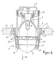
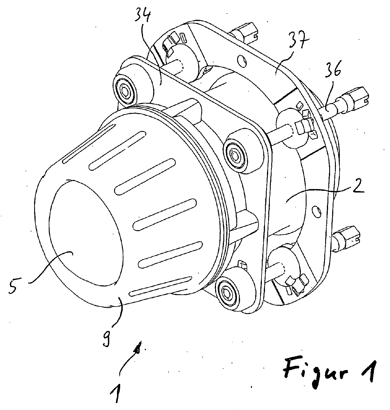
Figur 1- eine perspektivische Darstellung einer Leuchteinheit,
Figur 2- einen Längsschnitt durch eine Leuchteinheit nach einer ersten Ausführungsform,
- Figur 3
- eine Explosionsdarstellung der Leuchteinheit gemäß
Figur 2, - Figur 4
- eine perspektivische Rückansicht eines Gehäuseringteils der Leuchteinheit und
Figur 5- einen Längsschnitt durch eine Leuchteinheit nach einer zweiten Ausführungsform.
- FIG. 1
- a perspective view of a lighting unit,
- FIG. 2
- a longitudinal section through a lighting unit according to a first embodiment,
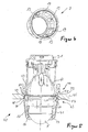
- FIG. 3
- an exploded view of the lighting unit according to Figure 2,
- FIG. 4
- a rear perspective view of a Gehäuseringteils the light unit and
- FIG. 5
- a longitudinal section through a lighting unit according to a second embodiment.
Eine Leuchteinheit 1 für Fahrzeuge kann zum einen als Scheinwerfer oder als
Leuchte, beispielsweise als Blinkleuchte oder dergleichen eingesetzt werden.
Die Leuchteinheit 1 kann zum einen in einer Karosserieöffnung eines Fahrzeugs
eingesetzt und an derselben befestigt sein. Zum anderen kann die
Leuchteinheit 1 auch zusammen mit weiteren Leuchteinheiten innerhalb eines
die mehreren Leuchteinheiten umfassendes Gehäuses mit einer die vorderseitige
Öffnung des Gehäuses abdeckenden klaren Abdeckscheibe angeordnet
sein.A
Die Leuchteinheit 1 weist als wesentliche Bauteile einen elliptischen Reflektor
2, eine in einer Reflektoröffnung 3 angeordnete Lichtquelle 4, ein dem Reflektor
2 vorgelagertes lichtdurchlässiges Abschlusselement 5 und einen das Abschlusselement
5 tragenden Halter 6 auf. Die Leuchteinheit 1 arbeitet nach
dem Projektionsprinzip und weist zu diesem Zweck in einem zweiten Brennpunkt
des Reflektors 2 eine Blende 7 auf, deren Blendkante 8 als Hell-Dunkel-Grenze
auf die Fahrbahn projiziert wird. Zu diesem Zweck ist das Abschlusselement
5 als eine Linse ausgebildet.The
Die Linse 5 ist lösbar mit dem Halter 6 verbunden. Zu diesem Zweck weist der
Halter 6 zum einen ein Gehäuseringteil 9 und zum anderen ein Einsatzteil 10
auf. Das Gehäuseringteil 9 und das Einsatzteil 10 sind hohlzylinderförmig ausgebildet,
wobei der Durchmesser des Einsatzteiles 10 kleiner ist der Durchmesser
des Gehäuseringteils 9, so dass es unter Anlage eines vorderen Randes
11 des Einsatzteils 10 an der planen rückseitigen Fläche der Linse 5 dasselbe
in das Gehäuseringteil 9 eingesetzt werden kann. Das Einsatzteil 10
weist auf einer dem Reflektor 2 zugewandten Seite mehrere in Umfangrichtung
verteilt angeordnete Befestigungslappen 12, die fluchtend zu innenseitig an
dem Gehäuseringteil 9 angeformte Befestigungsbohrungen 13 anordbar sind,
so dass das Einsatzteil 10 mittels Schrauben 14 kraftschlüssig mit dem Gehäuseteil
9 verbindbar ist. In der Montageposition liegt der vordere Rand 11 des
Einsatzteils 10 auf einem seitlichen Randabsatz 15 der Linse 5 an und verpresst
diesen unter Verformung einer zwischen dem Randabsatz 15 und einem
Muldenabsatz 16 des Gehäuseringteils 9 angeordneten Ringdichtung 17 gegen
den Muldenabsatz 16. Dabei liegt die Linse 5 lagesicher an dem Muldenabsatz
16 des Gehäuseringteils 9 an.The
Wie aus Figur 2 ersichtlich ist, erstreckt sich das Gehäuseringteil 9 in Lichtaustrittsrichtung
18 konusförmig verjüngend, so dass in einem mittleren oder in
einem der Linse 5 abgewandten Bereich des Gehäuseringteils 9 sich die Befestigungsbohrungen
13 ohne Auswirkung hinsichtlich der Lichtaustrittsfläche der
Linse 5 erstrecken können. As can be seen from FIG. 2, the housing ring part 9 extends in the
Der so gebildete Halter 6 für die Linse 5 ist lösbar mittels eines Drehverschlusses
mit dem Reflektor 2 verbunden. Der Drehverschluss ist als Bajonettverschluss
ausgebildet, wobei ein radial nach innen abragendes Halteelement 19
des Gehäuseringteils 9 eine in Umfangsrichtung verlaufende Haltenase 20 eines
vorderen Randes 21 des Reflektors 2 hintergreift. Sowohl das Halteelement
19 als auch die Haltenase 20 sind widerhakenförmig ausgebildet mit einer
in Montagedrehrichtung ansteigenden Schräge 22 und ist einem sich anschließenden
Einschnitt 23, in dem der in axialer Richtung vorspringende Teil 22 in
der Montageposition eingreift.The thus formed
Der Reflektor 2 weist an dem vorderen Rand 21 eine Ringnut 24 zur Aufnahme
eines Dichtrings 25 auf, so dass das Gehäuseringteil 9 luftdicht mit dem Reflektor
2 verbindbar ist. In der Montageposition drückt eine axial abstehende Ringnase
26 des Gehäuseringteils 9 unter Anlage an dem Dichtring 25 in die
Ringnut 24 des Reflektors 2 ein. Dabei bilden die Ringnase 26 und die Ringnut
24 jeweils eine Verbindungsfläche, zwischen denen umlaufend die Dichtung 25
angeordnet ist. Die Tiefe der Ringnut 24 ist derart gewählt, dass der Dichtring
25 vollständig durch den hinteren Rand des Gehäuseringteils 9 abgedeckt ist,
so dass kein Ausgasen des beispielsweise aus einem Silikonmaterial gefertigten
Dichtrings 25 weder in den Innenraum der Leuchteinheit 1 noch nach außen
hin erfolgen kann.The
Die Blende 7 ist mittels Schrauben 27 lösbar an dem vorderen Rand 21 des
Reflektors 2 befestigt. Dabei reicht ein Außenrand der Blende 7 nicht über eine
innere Wandung 28 der Ringnut 24 hinaus.The aperture 7 is releasably secured by
Die Lichtquelle 4 ist in einer von hinten in den Reflektor 2 mittels Schrauben 29
einschraubbaren Lampenfassung 30 eingefasst und in üblicher Weise arretiert.
Eine der Linse 5 abgewandte Öffnung der Lampenfassung 30 bzw. des Reflektors
2 ist mittels einer flexiblen Kappe 31 staubfrei abgedeckt. The light source 4 is in a back of the
Eine äußere Wandung 32 der Ringnut 24 bildet einen radial nach außen abstehenden
Kranz 32 des Reflektors 2, an dem Befestigungsaufnahmen 33 verteilt
in Umfangsrichtung zur Befestigung eines ersten Tragrahmens 34 angeordnet
sind. Der erste Tragrahmen 34 dient zur Befestigung des Reflektors 2 an einem
nicht dargestellten Karosserieteil des Kraftfahrzeugs. Zu diesem Zweck weist
der erste Tragrahmen umfangsseitig Bohrungen 35 auf, an denen Einstellschrauben
36 gelagert sind, die jeweils in einem axialen Abschnitt mit einem
zweiten Tragrahmen 37 verbunden sind, der an der Karosserie angebunden ist.
Der Innendurchmesser des zweiten Tragrahmens 37 ist größer als der Außendurchmesser
des Reflektors 2; er ist somit in einem radialen Abstand zu dem
Reflektor 2 angeordnet. Die Einstellschrauben 36 sind axial verschieblich in den
Bohrungen 35 gelagert, so dass die Leuchteinheit 1 zur Leuchtweitenregelung
verstellbar angeordnet ist.An
Alternativ kann, wie auch in Figur 2 dargestellt ist, die Leuchteinheit 1, die aus
dem Reflektor 2 und dem Halter 6 zusammengesetzt ist, mittels eines Drehverschlusses
55 an dem Tragrahmen 34 befestigt sein. Als Drehverschluss 55
kann ein Bajonettverschluss dienen.Alternatively, as shown in Figure 2, the
Der Innendurchmesser des ersten Tragrahmens 34 entspricht im wesentlichen
dem Außendurchmesser des Reflektors 2, so dass der erste Tragrahmen 34
bei der Montage mit Spiel unter fluchtender Anordnung der Befestigungsaufnahmen
33 zu den Bohrungen 38 des ersten Tragrahmens 34 angelegt werden
kann. Nachfolgend wird der erste Tragrahmen 34 durch Verschraubung mit
dem Reflektor 2 verbunden.The inner diameter of the
Nach einer alternativen Ausführungsform einer Leuchteinheit 40 gemäß Figur 5
kann im Unterschied zu der Leuchteinheit 1 nach der ersten Ausführungsform
ein Gehäuseringteil 41 und ein Reflektor 42 mittels eines Bajonettverschlusses
43 bzw. 44 an einem ersten Tragrahmen 45 befestigt sein. Die weiteren Bauteile
der Leuchteinheit 40 stimmen mit den Bauteilen der Leuchteinheit 1 überein
und sind daher mit den gleichen Bezugsziffern gekennzeichnet.According to an alternative embodiment of a
Zur Bildung des Bajonettverschlusses 43 zwischen dem Gehäuseringteil 41
und dem ersten Tragrahmen 45 weist derselbe auf einer der Linse 5 zugewandten
Seite sich in axialer Richtung erstreckende und umfangsseitig verteilt angeordnete
Hakenasen 46 auf, in die korrespondierende Halteelemente 47 des
Gehäuseringteils 41 eingreifen können. Im Vergleich zu dem vorhergehenden
Ausführungsbeispiel weist das Gehäuseringteil 41 eine größere Längserstreckung
auf. In übereinstimmender Weise greift eine Ringnase 48 des Gehäuseringteils
41 unter Anlage an einem Dichtring 49 in eine Ringnut 50 des ersten
Tragrahmens 45 ein. Die Befestigung des Gehäuseringteils 41 erfolgt in der
gleichen zuvor beschriebenen Weise.To form the
Zur Bildung des Bajonettverschlusses 44 zwischen dem Reflektor 42 und dem
ersten Tragrahmen 45 weist derselbe auf einer der Linse 5 abgewandten Seite
axial abstehende und im Umfangsrichtung verteilt angeordnete Haltenasen 51
auf, in die korrespondierende Hakenelemente 52 des Reflektors 42 klemmend
eingreifen. Dabei liegt der Reflektor 42 mit seinem vorderen Rand 53 an einer
inneren Randfläche 54 des ersten Tragrahmens 45 an. Der erste Tragrahmen
45 erstreckt sich in einer Ebene der Blende 7, so dass er im Vergleich zu der
ersten Ausführungsform weiter vorne angeordnet ist. Hierdurch ist die
Schwenkachse für die Leuchtweitenregelung weiter vorne gelagert, was sich
auf die Größe des Drehwinkels auswirkt.To form the
Die vorliegende Leuchteinheit 1, 40 ist als ein Scheinwerfer für die Abblendlichtfunktion
ausgebildet. Durch die schwenkbare Anordnung der Leuchteinheit
1, 40 kann diese zusätzlich beispielsweise für die Kurvenlichtfunktion eingesetzt
werden. The
Das Gehäuseringteil 9 und/oder das Einsatzteil 10 und/oder der Reflektor 2
können jeweils aus einem Metallgussmaterial oder einem Kunststoffmaterial
hergestellt sein.The housing ring part 9 and / or the
Claims (12)
Applications Claiming Priority (4)
| Application Number | Priority Date | Filing Date | Title |
|---|---|---|---|
| DE10360753 | 2003-12-23 | ||
| DE10360753 | 2003-12-23 | ||
| DE102004037244A DE102004037244A1 (en) | 2003-12-23 | 2004-07-31 | Lighting unit for vehicles |
| DE102004037244 | 2004-07-31 |
Publications (3)
| Publication Number | Publication Date |
|---|---|
| EP1547862A2 true EP1547862A2 (en) | 2005-06-29 |
| EP1547862A3 EP1547862A3 (en) | 2006-05-03 |
| EP1547862B1 EP1547862B1 (en) | 2008-08-27 |
Family
ID=34553337
Family Applications (1)
| Application Number | Title | Priority Date | Filing Date |
|---|---|---|---|
| EP20040029136 Expired - Lifetime EP1547862B1 (en) | 2003-12-23 | 2004-12-09 | Vehicle headlight |
Country Status (1)
| Country | Link |
|---|---|
| EP (1) | EP1547862B1 (en) |
Cited By (4)
| Publication number | Priority date | Publication date | Assignee | Title |
|---|---|---|---|---|
| EP2385298A1 (en) | 2010-05-07 | 2011-11-09 | Hella KGaA Hueck & Co. | Projection module for vehicles |
| FR3026462A1 (en) * | 2014-09-30 | 2016-04-01 | Valeo Vision Belgique | VEHICLE LIGHT DEVICE WITH PLATE OPTICAL ELEMENT WITH LIGHT SOURCE SUPPORT |
| FR3026823A1 (en) * | 2014-10-06 | 2016-04-08 | Peugeot Citroen Automobiles Sa | VEHICLE PROJECTOR |
| CN107543117A (en) * | 2016-06-28 | 2018-01-05 | 法雷奥照明比利时公司 | Vehicle lighting device with optical elements pinned by flexible support elements |
Family Cites Families (2)
| Publication number | Priority date | Publication date | Assignee | Title |
|---|---|---|---|---|
| JPH03101001A (en) * | 1989-09-13 | 1991-04-25 | Koito Mfg Co Ltd | Lighting fixture for vehicle |
| JPH11329011A (en) * | 1998-05-12 | 1999-11-30 | Koito Mfg Co Ltd | Automotive headlamp |
-
2004
- 2004-12-09 EP EP20040029136 patent/EP1547862B1/en not_active Expired - Lifetime
Cited By (13)
| Publication number | Priority date | Publication date | Assignee | Title |
|---|---|---|---|---|
| CN102252280A (en) * | 2010-05-07 | 2011-11-23 | 黑拉许克联合股份有限公司 | Projection module for vehicles |
| US8616743B2 (en) | 2010-05-07 | 2013-12-31 | Hella Kgaa Hueck & Co. | Projection module for vehicles |
| CN102252280B (en) * | 2010-05-07 | 2015-05-27 | 黑拉许克联合股份有限公司 | Projection module for vehicles |
| EP2385298A1 (en) | 2010-05-07 | 2011-11-09 | Hella KGaA Hueck & Co. | Projection module for vehicles |
| TWI675988B (en) * | 2014-09-30 | 2019-11-01 | 法雷奧照明比利時公司 | Vehicle lighting device with an optical element pressed against a light source support |
| FR3026462A1 (en) * | 2014-09-30 | 2016-04-01 | Valeo Vision Belgique | VEHICLE LIGHT DEVICE WITH PLATE OPTICAL ELEMENT WITH LIGHT SOURCE SUPPORT |
| WO2016050610A1 (en) * | 2014-09-30 | 2016-04-07 | Valeo Vision Belgique | Lighting device for a vehicle with an optical element clamped together with the light source support |
| CN106716008B (en) * | 2014-09-30 | 2019-12-06 | 法雷奥照明比利时公司 | Vehicle lighting device with optical element pressed against light source support |
| CN106716008A (en) * | 2014-09-30 | 2017-05-24 | 法雷奥照明比利时公司 | Lighting device for a vehicle with an optical element clamped together with the light source support |
| US10495279B2 (en) | 2014-09-30 | 2019-12-03 | Valeo Vision Belgique | Vehicle lighting device with an optical element pressed against a light source support |
| FR3026823A1 (en) * | 2014-10-06 | 2016-04-08 | Peugeot Citroen Automobiles Sa | VEHICLE PROJECTOR |
| WO2016055709A1 (en) * | 2014-10-06 | 2016-04-14 | Peugeot Citroen Automobiles Sa | Vehicle headlight |
| CN107543117A (en) * | 2016-06-28 | 2018-01-05 | 法雷奥照明比利时公司 | Vehicle lighting device with optical elements pinned by flexible support elements |
Also Published As
| Publication number | Publication date |
|---|---|
| EP1547862A3 (en) | 2006-05-03 |
| EP1547862B1 (en) | 2008-08-27 |
Similar Documents
| Publication | Publication Date | Title |
|---|---|---|
| DE19508472C2 (en) | Vehicle headlights with a number of lights | |
| DE69408494T2 (en) | Headlights for motor vehicles | |
| EP0637715B1 (en) | Replaceable light bulb mounting to a vehicle headlamp reflector | |
| DE19508471A1 (en) | Motor vehicle headlamp with watertight seal for opening where bulb is inserted | |
| DE4127403C2 (en) | Motor vehicle headlights with a screen arrangement | |
| DE2726951A1 (en) | LAMP REFLECTOR AND LAMP UNIT | |
| DE2916970B2 (en) | Automotive headlights | |
| DE19519655B4 (en) | Lighting device arranged on a front part of a vehicle | |
| DE69625409T2 (en) | Improved car headlights elliptical types | |
| EP1547862B1 (en) | Vehicle headlight | |
| DE3523080A1 (en) | UNIVERSALLY APPLICABLE PROTECTIVE CAP FOR HEADLIGHTS OF MOTOR VEHICLES | |
| DE60303770T2 (en) | A method of manufacturing a lighting or signaling device, and a lighting or signaling device made by this method | |
| DE3852351T2 (en) | Motor vehicle headlights. | |
| DE4133527C2 (en) | Headlights for motor vehicles | |
| DE102004037244A1 (en) | Lighting unit for vehicles | |
| DE19546370C2 (en) | Motor vehicle headlight with a headlight body and a lamp holder cover | |
| EP0985871B1 (en) | Headlamp and method of making the same | |
| EP1004473B1 (en) | Lighting unit for vehicle | |
| DE19735325A1 (en) | Motor vehicle head-lamp design | |
| DE4011703C1 (en) | ||
| DE102007028988A1 (en) | Headlights for vehicles | |
| DE1497316A1 (en) | Lighting fixture with retroreflective device | |
| DE3903868C1 (en) | Headlamp (headlight) for motor vehicles | |
| DE19831852A1 (en) | Vehicle headlights | |
| DE19815709C1 (en) | Attachment of lamp to vehicle, avoiding separate fastenings, fastening points and seals |
Legal Events
| Date | Code | Title | Description |
|---|---|---|---|
| PUAI | Public reference made under article 153(3) epc to a published international application that has entered the european phase |
Free format text: ORIGINAL CODE: 0009012 |
|
| AK | Designated contracting states |
Kind code of ref document: A2 Designated state(s): AT BE BG CH CY CZ DE DK EE ES FI FR GB GR HU IE IS IT LI LT LU MC NL PL PT RO SE SI SK TR |
|
| AX | Request for extension of the european patent |
Extension state: AL BA HR LV MK YU |
|
| PUAL | Search report despatched |
Free format text: ORIGINAL CODE: 0009013 |
|
| AK | Designated contracting states |
Kind code of ref document: A3 Designated state(s): AT BE BG CH CY CZ DE DK EE ES FI FR GB GR HU IE IS IT LI LT LU MC NL PL PT RO SE SI SK TR |
|
| AX | Request for extension of the european patent |
Extension state: AL BA HR LV MK YU |
|
| 17P | Request for examination filed |
Effective date: 20061030 |
|
| AKX | Designation fees paid |
Designated state(s): DE FR IT |
|
| 17Q | First examination report despatched |
Effective date: 20070706 |
|
| GRAP | Despatch of communication of intention to grant a patent |
Free format text: ORIGINAL CODE: EPIDOSNIGR1 |
|
| GRAS | Grant fee paid |
Free format text: ORIGINAL CODE: EPIDOSNIGR3 |
|
| GRAA | (expected) grant |
Free format text: ORIGINAL CODE: 0009210 |
|
| AK | Designated contracting states |
Kind code of ref document: B1 Designated state(s): DE FR IT |
|
| REF | Corresponds to: |
Ref document number: 502004007943 Country of ref document: DE Date of ref document: 20081009 Kind code of ref document: P |
|
| PLBE | No opposition filed within time limit |
Free format text: ORIGINAL CODE: 0009261 |
|
| STAA | Information on the status of an ep patent application or granted ep patent |
Free format text: STATUS: NO OPPOSITION FILED WITHIN TIME LIMIT |
|
| 26N | No opposition filed |
Effective date: 20090528 |
|
| PGFP | Annual fee paid to national office [announced via postgrant information from national office to epo] |
Ref country code: DE Payment date: 20131204 Year of fee payment: 10 |
|
| PGFP | Annual fee paid to national office [announced via postgrant information from national office to epo] |
Ref country code: IT Payment date: 20131212 Year of fee payment: 10 Ref country code: FR Payment date: 20131209 Year of fee payment: 10 |
|
| REG | Reference to a national code |
Ref country code: DE Ref legal event code: R119 Ref document number: 502004007943 Country of ref document: DE |
|
| REG | Reference to a national code |
Ref country code: FR Ref legal event code: ST Effective date: 20150831 |
|
| PG25 | Lapsed in a contracting state [announced via postgrant information from national office to epo] |
Ref country code: DE Free format text: LAPSE BECAUSE OF NON-PAYMENT OF DUE FEES Effective date: 20150701 |
|
| PG25 | Lapsed in a contracting state [announced via postgrant information from national office to epo] |
Ref country code: FR Free format text: LAPSE BECAUSE OF NON-PAYMENT OF DUE FEES Effective date: 20141231 |
|
| PG25 | Lapsed in a contracting state [announced via postgrant information from national office to epo] |
Ref country code: IT Free format text: LAPSE BECAUSE OF NON-PAYMENT OF DUE FEES Effective date: 20141209 |