EP1547862A2 - Projecteur de voiture - Google Patents
Projecteur de voiture Download PDFInfo
- Publication number
- EP1547862A2 EP1547862A2 EP04029136A EP04029136A EP1547862A2 EP 1547862 A2 EP1547862 A2 EP 1547862A2 EP 04029136 A EP04029136 A EP 04029136A EP 04029136 A EP04029136 A EP 04029136A EP 1547862 A2 EP1547862 A2 EP 1547862A2
- Authority
- EP
- European Patent Office
- Prior art keywords
- reflector
- holder
- lighting unit
- unit according
- front edge
- Prior art date
- Legal status (The legal status is an assumption and is not a legal conclusion. Google has not performed a legal analysis and makes no representation as to the accuracy of the status listed.)
- Granted
Links
Images


Classifications
-
- B—PERFORMING OPERATIONS; TRANSPORTING
- B60—VEHICLES IN GENERAL
- B60Q—ARRANGEMENT OF SIGNALLING OR LIGHTING DEVICES, THE MOUNTING OR SUPPORTING THEREOF OR CIRCUITS THEREFOR, FOR VEHICLES IN GENERAL
- B60Q1/00—Arrangement of optical signalling or lighting devices, the mounting or supporting thereof or circuits therefor
- B60Q1/02—Arrangement of optical signalling or lighting devices, the mounting or supporting thereof or circuits therefor the devices being primarily intended to illuminate the way ahead or to illuminate other areas of way or environments
- B60Q1/04—Arrangement of optical signalling or lighting devices, the mounting or supporting thereof or circuits therefor the devices being primarily intended to illuminate the way ahead or to illuminate other areas of way or environments the devices being headlights
- B60Q1/06—Arrangement of optical signalling or lighting devices, the mounting or supporting thereof or circuits therefor the devices being primarily intended to illuminate the way ahead or to illuminate other areas of way or environments the devices being headlights adjustable, e.g. remotely-controlled from inside vehicle
- B60Q1/076—Arrangement of optical signalling or lighting devices, the mounting or supporting thereof or circuits therefor the devices being primarily intended to illuminate the way ahead or to illuminate other areas of way or environments the devices being headlights adjustable, e.g. remotely-controlled from inside vehicle by electrical means including means to transmit the movements, e.g. shafts or joints
-
- F—MECHANICAL ENGINEERING; LIGHTING; HEATING; WEAPONS; BLASTING
- F21—LIGHTING
- F21S—NON-PORTABLE LIGHTING DEVICES; SYSTEMS THEREOF; VEHICLE LIGHTING DEVICES SPECIALLY ADAPTED FOR VEHICLE EXTERIORS
- F21S41/00—Illuminating devices specially adapted for vehicle exteriors, e.g. headlamps
- F21S41/20—Illuminating devices specially adapted for vehicle exteriors, e.g. headlamps characterised by refractors, transparent cover plates, light guides or filters
- F21S41/25—Projection lenses
- F21S41/255—Lenses with a front view of circular or truncated circular outline
-
- F—MECHANICAL ENGINEERING; LIGHTING; HEATING; WEAPONS; BLASTING
- F21—LIGHTING
- F21S—NON-PORTABLE LIGHTING DEVICES; SYSTEMS THEREOF; VEHICLE LIGHTING DEVICES SPECIALLY ADAPTED FOR VEHICLE EXTERIORS
- F21S41/00—Illuminating devices specially adapted for vehicle exteriors, e.g. headlamps
- F21S41/20—Illuminating devices specially adapted for vehicle exteriors, e.g. headlamps characterised by refractors, transparent cover plates, light guides or filters
- F21S41/29—Attachment thereof
- F21S41/295—Attachment thereof specially adapted to projection lenses
-
- F—MECHANICAL ENGINEERING; LIGHTING; HEATING; WEAPONS; BLASTING
- F21—LIGHTING
- F21S—NON-PORTABLE LIGHTING DEVICES; SYSTEMS THEREOF; VEHICLE LIGHTING DEVICES SPECIALLY ADAPTED FOR VEHICLE EXTERIORS
- F21S41/00—Illuminating devices specially adapted for vehicle exteriors, e.g. headlamps
- F21S41/50—Illuminating devices specially adapted for vehicle exteriors, e.g. headlamps characterised by aesthetic components not otherwise provided for, e.g. decorative trim, partition walls or covers
- F21S41/55—Attachment thereof
-
- F—MECHANICAL ENGINEERING; LIGHTING; HEATING; WEAPONS; BLASTING
- F21—LIGHTING
- F21S—NON-PORTABLE LIGHTING DEVICES; SYSTEMS THEREOF; VEHICLE LIGHTING DEVICES SPECIALLY ADAPTED FOR VEHICLE EXTERIORS
- F21S45/00—Arrangements within vehicle lighting devices specially adapted for vehicle exteriors, for purposes other than emission or distribution of light
- F21S45/50—Waterproofing
-
- B—PERFORMING OPERATIONS; TRANSPORTING
- B60—VEHICLES IN GENERAL
- B60Q—ARRANGEMENT OF SIGNALLING OR LIGHTING DEVICES, THE MOUNTING OR SUPPORTING THEREOF OR CIRCUITS THEREFOR, FOR VEHICLES IN GENERAL
- B60Q2900/00—Features of lamps not covered by other groups in B60Q
- B60Q2900/20—Arrangements for easy recycling, e.g. for easy dismantling or use of special materials
-
- Y—GENERAL TAGGING OF NEW TECHNOLOGICAL DEVELOPMENTS; GENERAL TAGGING OF CROSS-SECTIONAL TECHNOLOGIES SPANNING OVER SEVERAL SECTIONS OF THE IPC; TECHNICAL SUBJECTS COVERED BY FORMER USPC CROSS-REFERENCE ART COLLECTIONS [XRACs] AND DIGESTS
- Y02—TECHNOLOGIES OR APPLICATIONS FOR MITIGATION OR ADAPTATION AGAINST CLIMATE CHANGE
- Y02W—CLIMATE CHANGE MITIGATION TECHNOLOGIES RELATED TO WASTEWATER TREATMENT OR WASTE MANAGEMENT
- Y02W30/00—Technologies for solid waste management
- Y02W30/50—Reuse, recycling or recovery technologies
- Y02W30/82—Recycling of waste of electrical or electronic equipment [WEEE]
Definitions
- the invention relates to a light unit for vehicles with a cup-shaped Reflector, with a translucent terminating element upstream of the reflector, with a closing element carrying the holder, with a front edge of the reflector is connected.
- a lighting unit for vehicles is known, the a tubular housing and the light exit side opening thereof has a final cover. Inside the case is a Reflector, designed as a lens terminating element and a final element carrying holder arranged.
- a disadvantage of the known Light unit is the same relatively large transverse extent. This results by the presence of a cover, whose diameter is essential greater than the diameter of the end element.
- Object of the present invention is therefore a lighting unit for vehicles in such a way that with a small footprint a reliable Operation and improved recyclability is given.
- the invention is in connection with the preamble the patent claim 1, characterized in that on the one hand with the holder the reflector and / or the other the termination element with the holder and / or on the other hand, the holder with a support frame carrying the light unit and / or on the other hand, the front edge of the reflector with the Lighting unit carrying support frame is releasably connected.
- the particular advantage of the invention is that essential components the lighting unit are detachably connected to each other, so that a separate Disposal or recyclability of possibly from a ensures different components manufactured components.
- the components are not firmly connected by means of an adhesive, which when using the Light unit in a headlamp housing by outgassing an undesirable Deposit on the cover would cause.
- the detachable connection allows at least two components that detected during the manufacturing process in quality assurance Defects of individual components, the other components back into the manufacturing process can be integrated. This allows the production costs to reduce.
- a holder for a closure element and a reflector by means of a rotary closure, in particular a bayonet closure are connected together as components.
- a seal is provided between two mutually facing connecting surfaces of the holder on the one hand and the reflector on the other hand, so that the interior of the light unit is hermetically sealed to the outside.
- the seal is located on one of the connecting surfaces in the radial direction from the outside, so that due to a possible outgassing of the sealing material, such as silicone, a turbidity of the reflective surface and / or the closing element can not occur.
- a front edge of the reflector by means of a bayonet lock on a common support frame is releasably connected.
- the arrangement of the seal in the support frame can be displaced thereby, so that the impairment is reduced by a possible outgassing of the sealing material.
- the holder has a cap-shaped Housing ring on, on the front inside of the final element by means of an inside of the housing ring part applicable Insert element is connected by traction.
- the Insert element under compression of the closing element on the inside the Ge Reifeningmaschines bolted to the same. This can advantageously in a simple way, preferably consisting of a glass material terminating element from the existing of a metal material Ge Reifeningteil be removed.
- the housing ring part extends in Direction of light tapering cone-shaped, so that the screwing of the Insert element with the housing ring part in a region between the Termination element and the reflector can be done.
- the advantage here is the Room used for a screw connection, without the light emission of the End element is impaired.
- a lighting unit 1 for vehicles can be used as a headlight or as Lamp, for example, used as a flashing light or the like.
- the lighting unit 1 can firstly in a body opening of a vehicle be used and attached to the same.
- the Lighting unit 1 also together with other lighting units within a the housing comprising a plurality of light units with one the front side Opening the housing covering clear cover disc arranged be.
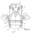
- the lighting unit 1 has as essential components an elliptical reflector 2, arranged in a reflector opening 3 light source 4, a reflector 2 upstream transparent end member 5 and a the final element 5 carrying holder 6 on.
- the lighting unit 1 works after the projection principle, pointing to this purpose in a second focus of the reflector 2 on a diaphragm 7, the blend edge 8 as a light-dark boundary is projected onto the roadway.
- the final element 5 is formed as a lens.
- the lens 5 is detachably connected to the holder 6.
- the Holder 6 on the one hand a housing ring part 9 and on the other hand an insert part 10th on.
- the housing ring part 9 and the insert part 10 are hollow-cylindrical, wherein the diameter of the insert 10 is smaller than the diameter of the housing ring part 9, so that it bears a front edge 11 of the insert 10 on the flat rear surface of the lens 5 the same can be used in the housing ring part 9.
- the insert 10 has on the reflector 2 side facing several in the circumferential direction distributed arranged fastening tabs 12, which in alignment with the inside the housing ring part 9 integrally formed mounting holes 13 can be arranged, so that the insert 10 by means of screws 14 frictionally with the housing part 9 is connectable.
- the housing ring part 9 extends in the light exit direction 18 cone-shaped tapering, so that in a middle or in one of the lens 5 facing away from the area of the housing ring part 9, the mounting holes 13 with no effect on the light exit surface of Lens 5 can extend.
- the thus formed holder 6 for the lens 5 is detachably by means of a rotary closure connected to the reflector 2.
- the twist lock is as a bayonet lock formed, wherein a radially inwardly projecting retaining element 19 of the housing ring part 9 a circumferentially extending retaining lug 20 of a front edge 21 of the reflector 2 engages behind.
- Both the retaining element 19 and the retaining lug 20 are barb-shaped with a in Montagerehraum rising slope 22 and is a subsequent Incision 23 in which the axially projecting part 22 in engages the mounting position.
- the reflector 2 has at the front edge 21 an annular groove 24 for receiving a sealing ring 25, so that the housing ring part 9 airtight with the reflector 2 is connectable.
- the annular nose 26 and the annular groove form 24 each have a connecting surface, between which circumferentially the seal 25th is arranged.
- the depth of the annular groove 24 is selected such that the sealing ring 25 is completely covered by the rear edge of the housing ring part 9, so that no outgassing of, for example, made of a silicone material Sealing ring 25 neither in the interior of the light unit 1 to the outside can take place.
- the aperture 7 is releasably secured by screws 27 to the front edge 21 of the Reflectors 2 attached.
- an outer edge of the aperture 7 does not have a inner wall 28 of the annular groove 24 also.
- the light source 4 is in a back of the reflector 2 by means of screws 29th screwed lamp holder 30 edged and locked in the usual way.
- One of the lens 5 facing away from the opening of the lamp holder 30 and the reflector 2 is covered dust-free by means of a flexible cap 31.
- An outer wall 32 of the annular groove 24 forms a radially outwardly projecting Wreath 32 of the reflector 2, distributed to the mounting receptacles 33 arranged in the circumferential direction for attachment of a first support frame 34 are.
- the first support frame 34 serves to attach the reflector 2 to a not shown body part of the motor vehicle.
- the first support frame circumferentially holes 35 on which adjusting screws 36 are mounted, each in an axial section with a second support frame 37 are connected, which is connected to the body.
- the inner diameter of the second support frame 37 is larger than the outer diameter the reflector 2; he is thus at a radial distance to the Reflector 2 arranged.
- the adjusting screws 36 are axially displaceable in the Drilled holes 35 so that the light unit 1 for headlight range control is arranged adjustable.
- the lighting unit 1, the off the reflector 2 and the holder 6 is composed by means of a rotary closure 55 may be attached to the support frame 34.
- a twist lock 55 can serve a bayonet lock.
- the inner diameter of the first support frame 34 substantially corresponds the outer diameter of the reflector 2, so that the first support frame 34th during installation with clearance under alignment of the mounting receptacles 33 are applied to the bores 38 of the first support frame 34 can. Subsequently, the first support frame 34 by screwing with connected to the reflector 2.
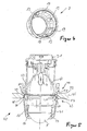
- a lighting unit 40 according to FIG. 5 may differ from the lighting unit 1 according to the first embodiment a housing ring part 41 and a reflector 42 by means of a bayonet closure 43 and 44 may be attached to a first support frame 45.
- the other components the lighting unit 40 coincide with the components of the lighting unit 1 and are therefore marked with the same reference numerals.
- the housing ring part 41 has a greater longitudinal extent on. In a matching manner engages a ring nose 48 of the housing ring part 41 under contact with a sealing ring 49 in an annular groove 50 of the first Support frame 45 a. The attachment of the housing ring part 41 takes place in the same way as described above.
- the bayonet lock 44 between the reflector 42 and the first support frame 45 has the same on a side facing away from the lens 5 axially projecting and circumferentially distributed retaining lugs 51st on, in the corresponding hook elements 52 of the reflector 42 clamping intervention.
- the reflector 42 is located with its front edge 53 at a inner edge surface 54 of the first support frame 45 at.
- the first support frame 45 extends in a plane of the aperture 7, so that he compared to the first embodiment is arranged further forward. This is the Swivel axle for the headlamp leveling further forward, which is on the size of the rotation angle.
- the present lighting unit 1, 40 is as a headlamp for the low beam function educated. Due to the pivotable arrangement of the lighting unit 1, 40 this can additionally be used for example for the cornering light function become.
- the housing ring part 9 and / or the insert part 10 and / or the reflector 2 can each be made of a metal casting material or a plastic material be prepared.
Landscapes
- Engineering & Computer Science (AREA)
- General Engineering & Computer Science (AREA)
- Mechanical Engineering (AREA)
- Non-Portable Lighting Devices Or Systems Thereof (AREA)
Applications Claiming Priority (4)
| Application Number | Priority Date | Filing Date | Title |
|---|---|---|---|
| DE10360753 | 2003-12-23 | ||
| DE10360753 | 2003-12-23 | ||
| DE102004037244A DE102004037244A1 (de) | 2003-12-23 | 2004-07-31 | Leuchteinheit für Fahrzeuge |
| DE102004037244 | 2004-07-31 |
Publications (3)
| Publication Number | Publication Date |
|---|---|
| EP1547862A2 true EP1547862A2 (fr) | 2005-06-29 |
| EP1547862A3 EP1547862A3 (fr) | 2006-05-03 |
| EP1547862B1 EP1547862B1 (fr) | 2008-08-27 |
Family
ID=34553337
Family Applications (1)
| Application Number | Title | Priority Date | Filing Date |
|---|---|---|---|
| EP20040029136 Expired - Lifetime EP1547862B1 (fr) | 2003-12-23 | 2004-12-09 | Projecteur de voiture |
Country Status (1)
| Country | Link |
|---|---|
| EP (1) | EP1547862B1 (fr) |
Cited By (4)
| Publication number | Priority date | Publication date | Assignee | Title |
|---|---|---|---|---|
| EP2385298A1 (fr) | 2010-05-07 | 2011-11-09 | Hella KGaA Hueck & Co. | Module de projection pour véhicules |
| FR3026462A1 (fr) * | 2014-09-30 | 2016-04-01 | Valeo Vision Belgique | Dispositif lumineux de vehicule avec un element optique plaque avec le support de source lumineuse |
| FR3026823A1 (fr) * | 2014-10-06 | 2016-04-08 | Peugeot Citroen Automobiles Sa | Projecteur de vehicule |
| CN107543117A (zh) * | 2016-06-28 | 2018-01-05 | 法雷奥照明比利时公司 | 具有用挠性支撑元件销接的光学元件的车灯装置 |
Family Cites Families (2)
| Publication number | Priority date | Publication date | Assignee | Title |
|---|---|---|---|---|
| JPH03101001A (ja) * | 1989-09-13 | 1991-04-25 | Koito Mfg Co Ltd | 車輌用灯具 |
| JPH11329011A (ja) * | 1998-05-12 | 1999-11-30 | Koito Mfg Co Ltd | 自動車用ヘッドランプ |
-
2004
- 2004-12-09 EP EP20040029136 patent/EP1547862B1/fr not_active Expired - Lifetime
Cited By (13)
| Publication number | Priority date | Publication date | Assignee | Title |
|---|---|---|---|---|
| CN102252280A (zh) * | 2010-05-07 | 2011-11-23 | 黑拉许克联合股份有限公司 | 用于汽车的投射模块 |
| US8616743B2 (en) | 2010-05-07 | 2013-12-31 | Hella Kgaa Hueck & Co. | Projection module for vehicles |
| CN102252280B (zh) * | 2010-05-07 | 2015-05-27 | 黑拉许克联合股份有限公司 | 用于汽车的投射模块 |
| EP2385298A1 (fr) | 2010-05-07 | 2011-11-09 | Hella KGaA Hueck & Co. | Module de projection pour véhicules |
| TWI675988B (zh) * | 2014-09-30 | 2019-11-01 | 法雷奧照明比利時公司 | 具有光學元件抵住光源支座之車輛照明裝置 |
| FR3026462A1 (fr) * | 2014-09-30 | 2016-04-01 | Valeo Vision Belgique | Dispositif lumineux de vehicule avec un element optique plaque avec le support de source lumineuse |
| WO2016050610A1 (fr) * | 2014-09-30 | 2016-04-07 | Valeo Vision Belgique | Dispositif lumineux de vehicule avec un element optique plaque avec le support de source lumineuse |
| CN106716008B (zh) * | 2014-09-30 | 2019-12-06 | 法雷奥照明比利时公司 | 具有压抵光源支撑件的光学元件的车辆照明装置 |
| CN106716008A (zh) * | 2014-09-30 | 2017-05-24 | 法雷奥照明比利时公司 | 具有压抵光源支撑件的光学元件的车辆照明装置 |
| US10495279B2 (en) | 2014-09-30 | 2019-12-03 | Valeo Vision Belgique | Vehicle lighting device with an optical element pressed against a light source support |
| FR3026823A1 (fr) * | 2014-10-06 | 2016-04-08 | Peugeot Citroen Automobiles Sa | Projecteur de vehicule |
| WO2016055709A1 (fr) * | 2014-10-06 | 2016-04-14 | Peugeot Citroen Automobiles Sa | Projecteur de véhicule |
| CN107543117A (zh) * | 2016-06-28 | 2018-01-05 | 法雷奥照明比利时公司 | 具有用挠性支撑元件销接的光学元件的车灯装置 |
Also Published As
| Publication number | Publication date |
|---|---|
| EP1547862A3 (fr) | 2006-05-03 |
| EP1547862B1 (fr) | 2008-08-27 |
Similar Documents
| Publication | Publication Date | Title |
|---|---|---|
| DE19508472C2 (de) | Fahrzeugscheinwerfer mit einer Anzahl von Leuchten | |
| DE69408494T2 (de) | Scheinwerfer für Kraftfahrzeuge | |
| EP0637715B1 (fr) | Dispositif de fixation de lampe sur un réflecteur de projecteur de véhicule | |
| DE19508471A1 (de) | Fahrzeugscheinwerfer mit wasserdichter Abdeckung | |
| DE4127403C2 (de) | Kraftfahrzeugscheinwerfer mit einer Sichtblendenanordnung | |
| DE3045424C2 (de) | Vorrichtung zum lagerichtigen Befestigen einer Lampe am Reflektor eines Kraftfahrzeugscheinwerfers | |
| DE10004700A1 (de) | Scheinwerfer für Kraftfahrzeuge | |
| DE2726951A1 (de) | Lampenreflektor und lampeneinheit | |
| DE2916970B2 (de) | Kraftfahrzeugscheinwerfer | |
| DE69625409T2 (de) | Verbesserter Kfz-Scheinwerfer elliptischen Types | |
| EP1547862B1 (fr) | Projecteur de voiture | |
| DE3523080A1 (de) | Universell verwendbare schutzkappe fuer scheinwerfer von kraftfahrzeugen | |
| DE60303770T2 (de) | Verfahren zur Herstellung von einer Beleuchtungs- oder Signaleinrichtung, und eine durch dieses Verfahren hergestellte Beleuchtungs- oder Signaleinrichtung | |
| DE3852351T2 (de) | Kraftfahrzeugscheinwerfer. | |
| DE102004037244A1 (de) | Leuchteinheit für Fahrzeuge | |
| DE19546370C2 (de) | Kraftfahrzeugscheinwerfer mit einem Scheinwerferkörper und einer Lampenfassungsabdeckung | |
| EP0985871B1 (fr) | Projecteur et procédé de fabrication de celui-ci | |
| EP1004473B1 (fr) | Unité d'éclairage pour véhicule | |
| DE4011703C1 (fr) | ||
| DE102007028988A1 (de) | Scheinwerfer für Fahrzeuge | |
| EP0679551A2 (fr) | Unité d'éclairage pour véhicule | |
| DE1497316A1 (de) | Beleuchtungskoerper mit Rueckstrahlvorrichtung | |
| DE3903868C1 (en) | Headlamp (headlight) for motor vehicles | |
| DE19831852A1 (de) | Fahrzeugscheinwerfer | |
| DE19815709C1 (de) | Befestigung für eine Leuchte an einem Fahrzeug |
Legal Events
| Date | Code | Title | Description |
|---|---|---|---|
| PUAI | Public reference made under article 153(3) epc to a published international application that has entered the european phase |
Free format text: ORIGINAL CODE: 0009012 |
|
| AK | Designated contracting states |
Kind code of ref document: A2 Designated state(s): AT BE BG CH CY CZ DE DK EE ES FI FR GB GR HU IE IS IT LI LT LU MC NL PL PT RO SE SI SK TR |
|
| AX | Request for extension of the european patent |
Extension state: AL BA HR LV MK YU |
|
| PUAL | Search report despatched |
Free format text: ORIGINAL CODE: 0009013 |
|
| AK | Designated contracting states |
Kind code of ref document: A3 Designated state(s): AT BE BG CH CY CZ DE DK EE ES FI FR GB GR HU IE IS IT LI LT LU MC NL PL PT RO SE SI SK TR |
|
| AX | Request for extension of the european patent |
Extension state: AL BA HR LV MK YU |
|
| 17P | Request for examination filed |
Effective date: 20061030 |
|
| AKX | Designation fees paid |
Designated state(s): DE FR IT |
|
| 17Q | First examination report despatched |
Effective date: 20070706 |
|
| GRAP | Despatch of communication of intention to grant a patent |
Free format text: ORIGINAL CODE: EPIDOSNIGR1 |
|
| GRAS | Grant fee paid |
Free format text: ORIGINAL CODE: EPIDOSNIGR3 |
|
| GRAA | (expected) grant |
Free format text: ORIGINAL CODE: 0009210 |
|
| AK | Designated contracting states |
Kind code of ref document: B1 Designated state(s): DE FR IT |
|
| REF | Corresponds to: |
Ref document number: 502004007943 Country of ref document: DE Date of ref document: 20081009 Kind code of ref document: P |
|
| PLBE | No opposition filed within time limit |
Free format text: ORIGINAL CODE: 0009261 |
|
| STAA | Information on the status of an ep patent application or granted ep patent |
Free format text: STATUS: NO OPPOSITION FILED WITHIN TIME LIMIT |
|
| 26N | No opposition filed |
Effective date: 20090528 |
|
| PGFP | Annual fee paid to national office [announced via postgrant information from national office to epo] |
Ref country code: DE Payment date: 20131204 Year of fee payment: 10 |
|
| PGFP | Annual fee paid to national office [announced via postgrant information from national office to epo] |
Ref country code: IT Payment date: 20131212 Year of fee payment: 10 Ref country code: FR Payment date: 20131209 Year of fee payment: 10 |
|
| REG | Reference to a national code |
Ref country code: DE Ref legal event code: R119 Ref document number: 502004007943 Country of ref document: DE |
|
| REG | Reference to a national code |
Ref country code: FR Ref legal event code: ST Effective date: 20150831 |
|
| PG25 | Lapsed in a contracting state [announced via postgrant information from national office to epo] |
Ref country code: DE Free format text: LAPSE BECAUSE OF NON-PAYMENT OF DUE FEES Effective date: 20150701 |
|
| PG25 | Lapsed in a contracting state [announced via postgrant information from national office to epo] |
Ref country code: FR Free format text: LAPSE BECAUSE OF NON-PAYMENT OF DUE FEES Effective date: 20141231 |
|
| PG25 | Lapsed in a contracting state [announced via postgrant information from national office to epo] |
Ref country code: IT Free format text: LAPSE BECAUSE OF NON-PAYMENT OF DUE FEES Effective date: 20141209 |