EP1548171B1 - Motor für Waschmaschinen - Google Patents
Motor für Waschmaschinen Download PDFInfo
- Publication number
- EP1548171B1 EP1548171B1 EP20040030657 EP04030657A EP1548171B1 EP 1548171 B1 EP1548171 B1 EP 1548171B1 EP 20040030657 EP20040030657 EP 20040030657 EP 04030657 A EP04030657 A EP 04030657A EP 1548171 B1 EP1548171 B1 EP 1548171B1
- Authority
- EP
- European Patent Office
- Prior art keywords
- bushing
- motor
- rotor frame
- rotor
- seating
- Prior art date
- Legal status (The legal status is an assumption and is not a legal conclusion. Google has not performed a legal analysis and makes no representation as to the accuracy of the status listed.)
- Expired - Lifetime
Links
- 238000005406 washing Methods 0.000 title claims description 45
- 239000011347 resin Substances 0.000 claims description 16
- 229920005989 resin Polymers 0.000 claims description 16
- 238000001816 cooling Methods 0.000 claims description 15
- 230000003014 reinforcing effect Effects 0.000 claims description 13
- 239000002184 metal Substances 0.000 claims description 12
- 238000000465 moulding Methods 0.000 claims description 9
- 238000005452 bending Methods 0.000 claims description 6
- 230000002708 enhancing effect Effects 0.000 claims description 4
- 238000000034 method Methods 0.000 description 11
- 238000004519 manufacturing process Methods 0.000 description 10
- 230000008569 process Effects 0.000 description 9
- 238000002347 injection Methods 0.000 description 8
- 239000007924 injection Substances 0.000 description 8
- 238000001746 injection moulding Methods 0.000 description 8
- 229910000831 Steel Inorganic materials 0.000 description 6
- 238000003780 insertion Methods 0.000 description 6
- 230000037431 insertion Effects 0.000 description 6
- 239000010959 steel Substances 0.000 description 6
- XLYOFNOQVPJJNP-UHFFFAOYSA-N water Substances O XLYOFNOQVPJJNP-UHFFFAOYSA-N 0.000 description 6
- 239000007788 liquid Substances 0.000 description 5
- 230000008901 benefit Effects 0.000 description 4
- 230000015572 biosynthetic process Effects 0.000 description 4
- 230000005540 biological transmission Effects 0.000 description 3
- 238000007664 blowing Methods 0.000 description 3
- 238000004049 embossing Methods 0.000 description 3
- 239000002991 molded plastic Substances 0.000 description 3
- 239000004033 plastic Substances 0.000 description 3
- 230000008878 coupling Effects 0.000 description 2
- 238000010168 coupling process Methods 0.000 description 2
- 238000005859 coupling reaction Methods 0.000 description 2
- 238000005520 cutting process Methods 0.000 description 2
- 238000012986 modification Methods 0.000 description 2
- 230000004048 modification Effects 0.000 description 2
- 238000003825 pressing Methods 0.000 description 2
- 230000005855 radiation Effects 0.000 description 2
- 238000010008 shearing Methods 0.000 description 2
- 238000009987 spinning Methods 0.000 description 2
- 238000003466 welding Methods 0.000 description 2
- 230000008859 change Effects 0.000 description 1
- 230000000295 complement effect Effects 0.000 description 1
- 230000001419 dependent effect Effects 0.000 description 1
- 230000000994 depressogenic effect Effects 0.000 description 1
- 230000008030 elimination Effects 0.000 description 1
- 238000003379 elimination reaction Methods 0.000 description 1
- 230000004907 flux Effects 0.000 description 1
- 230000017525 heat dissipation Effects 0.000 description 1
- 239000011810 insulating material Substances 0.000 description 1
- 230000003993 interaction Effects 0.000 description 1
- 239000000463 material Substances 0.000 description 1
- 239000012811 non-conductive material Substances 0.000 description 1
- 238000013021 overheating Methods 0.000 description 1
- 238000012545 processing Methods 0.000 description 1
- 238000004080 punching Methods 0.000 description 1
- 238000000926 separation method Methods 0.000 description 1
- 230000001629 suppression Effects 0.000 description 1
- 230000008016 vaporization Effects 0.000 description 1
- 238000009834 vaporization Methods 0.000 description 1
Images






Classifications
-
- H—ELECTRICITY
- H02—GENERATION; CONVERSION OR DISTRIBUTION OF ELECTRIC POWER
- H02K—DYNAMO-ELECTRIC MACHINES
- H02K1/00—Details of the magnetic circuit
- H02K1/06—Details of the magnetic circuit characterised by the shape, form or construction
- H02K1/22—Rotating parts of the magnetic circuit
- H02K1/27—Rotor cores with permanent magnets
- H02K1/2786—Outer rotors
- H02K1/2787—Outer rotors the magnetisation axis of the magnets being perpendicular to the rotor axis
- H02K1/2789—Outer rotors the magnetisation axis of the magnets being perpendicular to the rotor axis the rotor consisting of two or more circumferentially positioned magnets
- H02K1/2791—Surface mounted magnets; Inset magnets
-
- D—TEXTILES; PAPER
- D06—TREATMENT OF TEXTILES OR THE LIKE; LAUNDERING; FLEXIBLE MATERIALS NOT OTHERWISE PROVIDED FOR
- D06F—LAUNDERING, DRYING, IRONING, PRESSING OR FOLDING TEXTILE ARTICLES
- D06F37/00—Details specific to washing machines covered by groups D06F21/00 - D06F25/00
- D06F37/30—Driving arrangements
- D06F37/304—Arrangements or adaptations of electric motors
-
- H—ELECTRICITY
- H02—GENERATION; CONVERSION OR DISTRIBUTION OF ELECTRIC POWER
- H02K—DYNAMO-ELECTRIC MACHINES
- H02K1/00—Details of the magnetic circuit
- H02K1/06—Details of the magnetic circuit characterised by the shape, form or construction
- H02K1/22—Rotating parts of the magnetic circuit
- H02K1/28—Means for mounting or fastening rotating magnetic parts on to, or to, the rotor structures
- H02K1/30—Means for mounting or fastening rotating magnetic parts on to, or to, the rotor structures using intermediate parts, e.g. spiders
-
- H—ELECTRICITY
- H02—GENERATION; CONVERSION OR DISTRIBUTION OF ELECTRIC POWER
- H02K—DYNAMO-ELECTRIC MACHINES
- H02K21/00—Synchronous motors having permanent magnets; Synchronous generators having permanent magnets
- H02K21/12—Synchronous motors having permanent magnets; Synchronous generators having permanent magnets with stationary armatures and rotating magnets
- H02K21/22—Synchronous motors having permanent magnets; Synchronous generators having permanent magnets with stationary armatures and rotating magnets with magnets rotating around the armatures, e.g. flywheel magnetos
-
- H—ELECTRICITY
- H02—GENERATION; CONVERSION OR DISTRIBUTION OF ELECTRIC POWER
- H02K—DYNAMO-ELECTRIC MACHINES
- H02K7/00—Arrangements for handling mechanical energy structurally associated with dynamo-electric machines, e.g. structural association with mechanical driving motors or auxiliary dynamo-electric machines
- H02K7/14—Structural association with mechanical loads, e.g. with hand-held machine tools or fans
Definitions
- the present invention relates to motors applicable to washing machines, and more particularly, a direct coupling type motor for a washing machine, which is coupled to a drum of the washing machine directly, for rotating the drum.
- a motor for a washing machine including a rotatable tub in which an agitator is disposed is known from US 6,049,930 .
- the motor comprises the features of the preamble of independent claim 1.
- a motor for a drum type washing machine comprising a stator fitted at a rear surface of a tub and having a plurality of slots on which a coil is wound, a rotor provided on an outer side of stator with a permanent magnet and connected to a washing drum in that the tub by a driving shaft and isolating means for isolating a gap between the stator and the rotor is known from US 2003/0132675 . According to this document, the rotor is fixed to the driving shaft by using fixing elements.
- a structure of a rotor for an outer rotor type brushless motor is known from EP 1 018 795 .
- the structure of the rotor for the brushless motor includes a steel plate frame provided with a base plate unit in a disc shape having a plurality of insertion holes at its centre portion, a plurality of radiation holes being formed at a circumferential portion of the insertion holes, a plurality of blades being formed at side portions of the radiation holes by cutting, a back yoke unit curved and extended in the upward direction, having a predetermined height at the circumferential portion of the base plate unit, and a radius-direction enhancing unit formed at the upper end portion of the back yoke unit.
- the radius-direction enhancing unit is formed vertically curved and extended in the outward direction at the upper end portion of the back yoke unit in order to enhance stiffness of the steel plate frame in the radius direction. According to an example, the radius-direction enhancing unit is extendedly formed in a reverse U-shape in the outward direction at the upper end portion of the back yoke unit.
- a rotor of a related art motor for the washing machine, injection molded of plastic entirely, requires very complicate mold, and fabrication process, and is liable to have shrinkage during cooling of the injection molded plastic, unable to obtain an original shape as it is.
- FIG 1 illustrates a section of a rotor of a motor applied to a related art washing machine.
- the related art rotor is provided with a rotor frame 1 of injection molded plastic which forms an exterior of the rotor, magnets 3 secured to an inside surface of an outer edge of the rotor frame 1, each with an N-pole and an S-pole arranged alternately, a back yoke 2 on an outer side of the magnets 3 for forming a flux path, heat dissipation frames 7 formed as one body with the rotor frame 1 on an underside thereof for forced movement of air to cool the motor, a driving shaft 5 inserted in a pass through hole in a central portion of the rotor frame 1, a serration 4 at a portion the driving shaft 5 and the rotor frame 1 come into contact for secure rotation of the driving shaft 5, a fastening bolt 6 inserted in, and fastened to the driving shaft 5, and reinforcing ribs 8 projected from an upper side and/or a lower side of the rotor frame 1, for reinforcing the rotor frame 1.
- the rotor of plastic of the related art washing machine has a hazard in that the rotor is liable to deform by an external impact. Also, since the mold is complicate for injection molding of the complicated rotor shape, the injection molding is difficult.
- the injection molded plastic may undergo deformation after the injection molding, an injection molded body is liable to have a shape different from a shape originally intended. If fabrication of the rotor frame 1 to exact dimensions is failed due to deformation occurred during the injection molding process, particularly, a cooling process, the rotor frame 1 causes interference with other parts, such as a stator of the motor, to cause the washing machine being out of order.
- the rotor frame 1 may be deformed by external force possible to occur during operation of the washing machine, and interfere with other parts, to make the washing machine inoperative.
- the present invention is directed to a motor for a washing machine that substantially obviates one or more problems due to limitations and disadvantages of the related art.
- An object of the present invention is to provide a motor for a washing machine, which can improve security of operation of the washing machine.
- Another object of the present invention is to provide a motor for a washing machine, which requires no complicated injection molding to enable fabrication by simple work, and save production cost.
- a motor for a washing machine includs a driving shaft coupled to a drum of the washing machine, a stator for forming a magnetic field by means of a coil wound on a core, and a rotor rotatably mounted on an outside of the stator coupled to the driving shaft for driving the driving shaft, wherein the rotor including a rotor frame of metal having magnets attached to an inside surface of an outer end, a back yoke on an outside surface of the outer end of the rotor frame for reinforcing the rotor frame and forming a magnetic path, a shaft supporting housing at a center of the rotor frame having one end portion of the driving shaft secured thereto, a bushing of a non-conductive resin having the shaft supporting housing formed as one body at a center, the bushing being secured to the rotor frame, and fastening members for fastening the bushing to the
- a motor for a washing machine includes a driving shaft coupled to a drum of the washing machine, a stator for forming a magnetic field by means of a coil wound on a core, and a rotor rotatably mounted on an outside of the stator coupled to the driving shaft for driving the driving shaft, wherein the rotor includes a rotor frame of metal having magnets attached to an inside surface of an outer end, a back yoke on an outside surface of the outer end of the rotor frame for reinforcing the rotor frame and forming a magnetic path, a shaft supporting housing of metal at a center of the rotor frame having one end portion of the driving shaft secured thereto, a bushing of a non-conductive resin having the shaft supporting housing formed as one body at a center by insert molding, the bushing being secured to the rotor frame, fastening members for fastening the bushing to the rotor frame, and guide members for guiding a fastening position of the bushing to the
- a motor for a washing machine includes a driving shaft coupled to a drum of the washing machine, a stator for forming a magnetic field by means of a coil wound on a core, and a rotor rotatably mounted on an outside of the stator coupled to the driving shaft for driving the driving shaft, wherein the rotor includes a rotor frame of metal having magnets attached to an inside surface of an outer end, a back yoke on an outside surface of the outer end of the rotor frame for reinforcing the rotor frame and forming a magnetic path, a shaft supporting housing at a center of the rotor frame having one end portion of the driving shaft secured thereto, and a bushing of a non-conductive material insert molded as one body with the shaft supporting housing and the rotor frame, for fixedly securing the shaft supporting housing and the rotor frame.
- the washing machine of the present invention can make stable operation even at spinning, and reduce hazard of current leakage.
- the drum type washing machine includes a case 10 which forms an exterior of the washing machine, a tub 11 mounted in the case 10 for holding water, a drum 12 mounted in the tub 11 for rotating in a state water and laundry are held therein to perform washing with friction between the water and the laundry, and a motor 30 directly coupled to a rear end of a driving shaft 25 secured to a rear of the drum 12.
- the motor 30 includes a stator 31 secured to a rear of the tub 11, and a rotor 40 rotatably mounted on an outside of the stator 31 having a center portion fixedly coupled to a rear end portion of the driving shaft 25.
- the stator 31 has coils 33 wound on an outer circumference, for receiving external power.
- the rotor 40 rotates by electro-magnetic force generated in relation to the stator 31.
- the motor 30 of the present invention is an outer rotor type motor in which the stator 31 is positioned at an inside, and the rotor 40 is positioned at an outside spaced a distance away outwardly from the stator 31.
- the present invention suggests to improve a structure of the rotor 40.
- the motor for a washing machine of the present invention is a BLDC motor, of which rotation speed, rotation phase, and so on can be controlled with reference to a position of the rotor sensed at a predetermined sensor that senses a rotation state of the rotor.
- a motor in accordance with a first preferred embodiment of the present invention will be described in detail, with reference to FIGS. 3 to 8 .
- the motor includes a stator 31 having a core with a coil wound thereon, and a rotor 40 rotatably mounted on an outside of the stator.
- the stator 31 is secured to the tub 11 (see FIG 2 )
- the rotor 40 is secured to the drum 12 (see FIG 2 ) with the driving shaft 25, to transmit a torque from the rotor 40 to the drum 12.
- the rotor 40 includes a rotor frame 41 of metal which is a main body of the rotor 40, a shaft supporting housing 60 having the driving shaft 25 inserted therein for transmission of the rotating force to the driving shaft 25, a bushing 70 injection molded in a state the shaft supporting housing is inserted therein, and secured to the rotor frame 41, and a nut 76 for fastening the driving shaft 25 inserted in the shaft supporting housing 60.
- the rotor frame 41 of the rotor 40 is formed of a metal, such as steel.
- the rotor frame 41 has magnets 46 on an inside surface of an upward bent portion of an outer end portion thereof, and a back yoke 45 on an outside surface of the upward bent portion.
- Outward and/or downward bent portions at the outer end portion of the rotor frame 41 serve as a reinforcing portion 44 for reinforcing the rotor frame 41.
- the rotor frame 41 has a molded portion 48 on an outside of the back yoke 45 for fixed securing the back yoke to the rotor frame 41, to prevent the back yoke from falling off the rotor frame 41.
- the rotor frame 41 has a resin adhering portion 47 at a predetermined position where the molded portion 48 is contact. Since the resin of the molded portion 48 is injected into an inside of the resin adhering portion 47 during molding of the molded portion 48, the bonding between the molded portion 48 and the rotor frame 41 can be made more rigidly, to make the molded portion to secure the back yoke 45 more rigidly.
- the resin adhering portion 47 may be a hole passed through the rotor frame 41 or a recess depressed in the rotor frame 41.
- the rotor frame 41 has fins 42 bent from predetermined positions of a horizontal surface for blowing air during rotation of the rotor 40, to cool and dehumidifying from the motor.
- the fin 42 blows air toward the stator 31 during rotation of the rotor frame 41.
- the air blowing enables easy vaporization of moisture, such as dew, which can be formed due to a temperature change of the washing machine by convection. Moreover, by cooling the motor, the air blowing prevents the motor from overheating.
- the embossing 43 prevents the rotor frame 41 from deforming at spinning of the motor up to 2,000rpm, to make the washing machine operative regularly.
- the fins 42 and the embossings 43 can be formed spontaneously by pressing a predetermined steel plate cut by punching with a predetermined mold.
- the rotor frame 41 has drain holes 52 in the horizontal surface for draining water.
- the shaft supporting housing 60 is injected molded in a state inserted in the bushing.
- the bushing 70 is placed on one side of the rotor frame 41 in a state the shaft supporting housing 60 is injection molded in the bushing 70, the bushing 70 is fastened to the rotor frame 41 with predetermined fastening members, such as bolt, and the like. Since the bushing 70 is formed of resin that is an insulating material, the rotor frame 41 is not conductive with the shaft supporting housing 60.
- the shaft supporting housing 60 cylindrical in overall, has a hole in an up/down direction with the driving shaft 25 inserted therein.
- the shaft supporting housing 60 is formed as one body with the bushing 70 during the bushing 70 is molded of an injection molding liquid.
- the shaft supporting housing 60 has at least one comparatively large projection 61 from an outside circumference, and an external serration 63 over the projection 61.
- the external serration 63 may be coupled to a shaft different from the driving shaft 25 selectively, for transmission of rotation force from the rotor 40. Since the external serration 63 at a lower portion is insert molded with the bushing 70, the coupling of the bushing 70 and the external serration 63 can be stronger to a shearing force.
- the shaft supporting housing 60 may be sintered of metal.
- the shaft supporting housing 60 is fabricated as one body with the shaft supporting housing 60 at a center thereof.
- the bushing 70 does not slip on the rotor frame 41 by a shearing force generated during rotation of the rotor 40.
- torque induced on the magnets 46 owing to electro-magnetic interaction between the stator 31 and the magnets 46 is transmitted to the driving shaft 25 through the rotor frame 41 and the bushing 70, when the bushing 70 is required to be rigidly fixed to the rotor frame 41 for secure transmission of the torque to the driving shaft 25.
- the bushing 70 has three seating projections 71 arranged at regular intervals extended downward from the bushing 70, and a plurality of bushing side fastening holes 72 arranged at regular intervals passed through the bushing 70, for inserting bolts 74.
- a cooling hole 73 In the center portion of the seating projection 71, there is a cooling hole 73 for preventing deformation of the seating projection during cooling down after molding.
- the rotor frame 41 has seating guides 49 for inserting the seating projections 71 respectively, to guide a position of the bushing 70, and frame side fastening holes 50 at positions facing the bushing side fastening holes 72.
- the bushing 70 is secured to the rotor frame 41 according to the following process.
- the shaft supporting housing 60 inserted in the bushing 70.
- the seating projections 71 are inserted in the seating guides 49, respectively.
- the seating projections 71 and the seating guides 49 formed at least two respectively enable exact positioning of the bushing 70.
- the rotor frame 41 has a seating flange 51 for inserting the bushing 70 therein, and the center portion of the busing 70 is formed in complementary to the seating flange 51.
- the seating projections 71 and the seating guides 49 not only enable convenient seating of the bushing 70, but also serve to prevent separation of the bushing 70 and the rotor frame 41 during rotation of the rotor 40, and to prevent the bushing 70 suffering from damage.
- the bushing 70 is conveniently seated on the seating flange 51 of the rotor frame 51 owing to the seating projections 71 and the seating guides 49, bolts 74 are inserted in the frame side fastening holes 50, and the bushing side fastening holes 72, and nuts 75 are screwed into end portions of the bolts 74, to fasten the bolts 74. With the bolts 74 and the nuts 75, the bushing 70 is rigidly secured to the rotor frame 41. It is preferable that the seating projections 71 and the bushing side fastening holes 72 are formed at equal intervals at equal distances from the center of the bushing 70 alternately, for balancing.
- FIGS. 6 , 7 , and 8 illustrate perspective views of rotor frames showing the steps of a process for fabricating a rotor frame.
- the rotor frame 41 has the magnets 46 and the back yoke 45 placed on an inside and an outside sidewalls respectively, wherein FIG 6 illustrates a state the back yoke 45 is not attached thereto yet, and FIG 7 illustrates a state after the back yoke 45 is attached thereto.
- the back yoke 45 may be attached to the outside surface of the rotor frame 41 by any one of methods, such as welding, bonding, or press fitting.
- FIG 8 illustrates a state the molded portion 48 is formed at an outside of the back yoke 45 by insert molding.
- the resin is inserted in the resin adhering portion 47, to secure the molded portion 48 to the rotor frame 41 more rigidly.
- the molded portion 48 formed to cover the back yoke 45 fully enables rigid attachment of the back yoke 45 without falling off the rotor frame 41 during rotation of the rotor 40.
- the back yoke 45 not only forms a magnetic path, but also reinforces the outer end of the rotor frame 41, to resist to an external vibration, strongly.
- the molded portion 48 may be formed to cover the bottom of the back yoke 45 or cover entirely, to secure the back yoke 45, more rigidly.
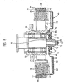
- FIG 9 illustrates a section of key parts of a motor in accordance with a second preferred embodiment of the present invention.
- the motor in accordance with a second preferred embodiment of the present invention illustrated in FIG 9 is identical or similar to the motor in accordance with a first preferred embodiment of the present invention in most of the parts, except that the motor of the second embodiment has the bushing 170 fastened from an underside of the rotor frame 141 to upward.
- the shaft supporting housing 60 is secured to an inside of the bushing 170 as the shaft supporting housing 60 is insert molded with the bushing 170.
- the seating projections 171 are projected upward from the bushing 170, and the seating flange 151 is projected upward from the rotor frame 141.
- This structure enables the bushing 170 placed from a lower side to an upper side of the rotor frame 141, and secured at the position.
- the unexplained reference numeral 173 denotes a cooling hole for preventing deformation of the seating projection 171 during cooling after molding.
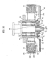
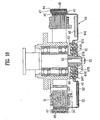
- FIGS. 10 and 11 illustrate motors in accordance with a third preferred embodiment of the present invention.
- a basic configuration of this embodiment is identical to the first embodiment, except that a rotor frame 241 of the motor of the third embodiment has an outer end portion bent at a bent portion 281 by 180° to overlap in two layers, to form a back yoke 282.
- the back yoke 282 is secured to an outside of the rotor frame 241 with a joint portion 283. If the end portion of the rotor frame 241 is bent to overlap in two layers, the outside circumferential portion of the rotor frame 241 can have a thickness thicker than a required thickness.
- a total thickness of the outer end portion of the rotor frame 241 bent at the bent portion 281 enables to perform a function of the back yoke 282 of forming a magnetic path.
- the back yoke can serve as a reinforcing portion for preventing deformation of the rotor frame 241 during rotation by reinforcing strength of the rotor frame 241 itself.
- the back yoke 282 is a bent portion, the back yoke 282 has an elastic force for restoring to an original shape.
- the joint portion serves to prevent deformation of the back yoke 282 by the elastic force.
- the joint portion 283 may be formed by various methods, such as welding, screw fastening, and so on, as far as the opposite sides of the bent rotor frame 241 are joined.
- the back yoke 282 is formed by bending the rotor frame once
- the rotor frame 241 may be bent by two, or more than two times within a range processing of the rotor frame 241 is permitted, to form the back yoke at a thickness that is comparatively thick.
- an edge of the rotor frame may be cut in a triangular shape at regular intervals, before bending, in formation of the back yoke 282.
- FIG 12 illustrates a section of key parts of a motor in accordance with a fourth preferred embodiment of the present invention, which is a variation of the motor in FIG. 10 .
- the fourth embodiment motor has the outer end portion of the rotor frame 341 bent at a bent portion by 180°, to overlap in two layers, so that the overlapped portion serves as a back yoke 382.
- the motor of the fourth embodiment has the bushing 370 fastened upward from an underside of the rotor frame 341.
- the shaft supporting housing 60 is secured to an inside of the bushing 370 as the shaft supporting housing 60 is insert molded in the bushing 370.
- the seating flange 351 is projected upward from the rotor frame 341.
- the seating projections 371 are projected upward from the bushing 370, and inserted in the seating guides 349 on the rotor frame 341. This structure enables the bushing 370 arranged upward from the underside of the rotor frame 341 and fastened to the rotor frame 341 at the position with bolts 74 and nuts 75.
- FIGS. 13 to 16 illustrate motors in accordance with a fifth preferred embodiment of the present invention.
- the motor in accordance with a fifth preferred embodiment of the present invention is the same with the motor in accordance with a first preferred embodiment of the present invention, except that the configurations of the seating projections 471 and the seating guides 449 for positioning the bushing 470 at the frame 441 of the fifth embodiment are different from the same of the first embodiment.
- the bushing 470 of the fifth embodiment motor has three bushing side fastening holes 472 at regular intervals. There is the seating projection 471 on an underside of the bushing 470 in the vicinity of each of the bushing side fastening holes 472, for reinforcing the bushing side fastening hole 472.
- a seating flange 451 for placing the bushing 470, and three frame side fastening holes 450 aligned with the bushing side fastening holes 450 for fastening the bushing 470 to the rotor frame 441 after the bushing 470 is placed thereon.
- a seating guide 449 on an outer side of each of the frame side fastening holes 450. It is preferable that the seating guide 449 and the frame side fastening hole 450 are positioned in the same radial line, and a distance between each pair of the seating guide 449 and the frame side fastening hole 450 is the same.
- the seating projection 471 has a right triangular shape having a height that becomes the higher as it goes toward an outer side. This right triangular shape of the seating projection 471 enables to enhance a crack running suppression effect even if a crack is formed at the bushing side fastening hole 472.
- the seating projection 471 and the bushing side fastening hole 472 are spaced by a predetermined distance 'L'. This enables to provide a predetermined distance constructed of a material of the rotor frame 441 between the seating guide 449 of the rotor frame 441 and the frame side fastening hole 450, to enhance a strength of the rotor frame 441.
- the rotor frame 441 is formed of steel.
- the extension of the seating projection 471 the outside circumference of the bushing 470 is not required necessarily, but the seating projection may end at a position distanced inwardly from the outside circumference of the bushing 470.
- the seating projections 471 and the seating guides 449 at the bushing 470 and the rotor frame 441 enable exact positioning of the bushing 470 with respect to the rotor frame 441 as the seating projections 471 are inserted in the seating guides 449 at the time of fastening the bushing 470 to the rotor frame 441.
- the frame side fastening holes 450 and the bushing side fastening holes 472 are aligned exactly, to enable easy placing of the bolts 74 both in the frame side fastening holes 450 and the bushing side fastening holes 472, and fastening with nuts 75.
- the seating projections 471 and the seating guides 449 not only enable the convenient seating of the bushing 470, but also prevent the bushing 470 suffering from damage.
- the seating projections 471 are, not only able to guide seating of the bushing 470, but also prevent the bushing side fastening holes 472 suffering from damage by external force from the bolts 74 because the seating projections 471 are formed in the same radial lines on an outer side of the bushing side fastening holes 472, respectively.
- the seating projection 471 serves as a reinforcing member at a position in the same radial line with the bushing side fastening hole 472, to stop running of a crack at the seating projection 471 even if the crack starts from the bushing side fastening hole 472, thereby preventing excessive damage of the bushing 470.
- FIG 17 illustrates a motor in accordance with a sixth preferred embodiment of the present invention, which is a variation of the motor in FIG 12 , and different from the motor of the fifth embodiment in that the bushing 570 of the motor of the sixth embodiment is fastened directed upward from the underside of the rotor frame 541.
- the seating projections 571 are projected upward from the bushing 570, and the seating flange 551 is projected upward from the rotor frame 541.
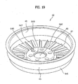
- FIGS. 18 and 19 illustrate motors in accordance with a seventh preferred embodiment of the present invention.
- a shaft supporting housing 60 is insert molded with a rotor frame 641 after the shaft supporting housing 60 is placed at a proper position on an inside of a housing inserting hole 642 at a center of the rotor frame 641, so that the shaft supporting housing 60 is secured at a position, and the injected resin forms a bushing 670.
- the bushing 670 is not fastened to the rotor frame 641, not with fastening members, like the bolts and nuts, but fixedly secured to the rotor frame 641 by one time of insert molding with liquid resin injected toward a position in the vicinity of the housing insertion hole 642 after the bushing 670 is placed in the same mold with the rotor frame 641 and the shaft supporting housing 60.
- the housing insertion hole 642 of the rotor frame 641 has a first bent surface 649 on an inside circumferential surface.
- the rotor frame 641 also has sustaining holes 647 at portions the rotor frame 641 are connected with the bushing 670, so that the liquid resin is injected into, and molded on entire areas of an inside and an outside of a center portion of the rotor frame 641.
- the sustaining hole 647 has a vertical second bent surface 648 extended downward therefrom.
- the bushing 670 has vertical first cooling holes 672, and vertical second cooling holes 673 in portions in the sustaining holes 647 of the rotor frame 641, and portions between the first bent surfaces 649 and the housing insertion hole 642.
- the first cooling holes 672 and the second cooling holes 673 serve to cooling down the liquid resin quickly in a process the bushing 670 is set.
- the quick cooling down of the bushing 670 enables to prevent possible shrinkage from occurring during setting of the liquid resin, permitting to fabricated the rotor 40 as an original shape intended to fabricate.
- the motors in all above embodiments have been described taking a motor coupled to a drum type washing machine, particularly, to a motor directly coupled to a drum type washing machine without a belt as an example, the motor of the present invention is applicable to a pulsator type washing machine, or an agitator type washing machine, in an identical or similar fashion.
- the motor of the present invention has the following advantages.
- the formation of the rotor frame of metal enhances a strength of the rotor frame, as well as operative security of the washing machine.
- the elimination of complicated injection molding process permits to reduce a time period required for fabrication, and improve the fabrication yield.
Landscapes
- Engineering & Computer Science (AREA)
- Power Engineering (AREA)
- Textile Engineering (AREA)
- Motor Or Generator Frames (AREA)
- Main Body Construction Of Washing Machines And Laundry Dryers (AREA)
- Iron Core Of Rotating Electric Machines (AREA)
- Connection Of Motors, Electrical Generators, Mechanical Devices, And The Like (AREA)
Claims (23)
- Motor für eine Waschmaschine, Folgendes umfassend: ein Antriebswelle (25), verbunden mit einer Trommel (12) der Waschmaschine, einen Stator (31) zum Bilden eines Magnetfeldes mittels einer um einen Kern gewundenen Spule und einen Rotor (40), der drehbar an eine Außenseite des Stators (31) montiert und an die Antriebswelle (25) zum Antreiben der Antriebswelle (25) montiert ist , wobei der Rotor (40) Folgendes umfasst:einen Rotorrahmen (241, 341) aus Metall mit Magneten (46), die an einer Innenfläche eines äußeren Endes angebracht sind;ein rückwärtiges Joch (282, 382) an einer Außenfläche des äußeren Endes des Rotorrahmens (241, 341) zum Verstärken des Rotorrahmens (241, 341) und zum Bilden eines magnetischen Pfads;ein die Welle tragendes Gehäuse (60) in der Mitte des Rotorrahmens (241, 341), an dem ein Endabschnitt der Antriebswelle (25) befestigt ist; undeine Buchse (70, 170, 370, 470, 570) aus einem nicht leitfähigen Harz mit dem in einem Körper ausgebildeten, die Welle tragenden Gehäuse (60) in der Mitte, wobei die Buchse (70, 170, 370, 470, 570) am Rotorrahmen (241, 341) befestigt ist;
dadurch gekennzeichnet, dassder Rotor (40) ferner separate Befestigungselemente (74, 75) zum Befestigen der Buchse (70, 170, 370, 470, 570) am Rotorrahmen (241, 341) umfasst, wobei die Buchse unabhängig vom Rotorrahmen ausgebildet ist und durch die separaten Befestigungselemente am Rotorrahmen befestigt ist; unddas rückwärtige Joch (282, 382) einen überlappenden Abschnitt aufweist, der durch wenigstens einmaliges Umbiegen des äußeren Endabschnitts des Rotorrahmens (241, 341) und Überlappen mit einer Umfangsfläche des Rotorrahmens (241, 341) in zwei Schichten gebildet wird,wobei der Motor ferner einen Verbindungsabschnitt (282, 383) zum festen Verbinden des rückwärtigen Jochs (282, 382) mit der Außenfläche des Rotorrahmens (241, 341) umfasst. - Motor nach Anspruch 1, wobei das die Welle tragende Gehäuse (60) in einem Teil mit der Buchse (70, 170, 370, 470, 570) durch Umspritzen geformt ist.
- Motor nach einem der Ansprüche 1 oder 2, wobei das die Welle tragende Gehäuse (60) aus Metall geformt ist.
- Motor nach Anspruch 1, ferner umfassend ein Führungselement, um eine Befestigungsposition der Buchse (70, 170, 370, 470, 570) zum Rotorrahmen (241, 341) hin zu führen.
- Motor nach Anspruch 4, wobei das Führungselement Folgendes umfasst:wenigstens einen Aufnahmevorsprung (71, 171, 371, 471, 571), der aus der Buchse (70, 170, 370, 470, 570) zum Rotorrahmen (241, 341) hin ragt; undwenigstens eine Aufnahmeführung (49, 349, 449), die durch den Rotorrahmen (241, 341) hindurch geht, zum jeweiligen Einsetzen der Aufnahmevorsprünge (71, 171, 371, 471, 571).
- Motor nach Anspruch 1, wobei das Befestigungselement Folgendes umfasst:mehrere sich durch die Buchse (70, 170, 370, 470, 570) erstreckende buchsenseitige Befestigungslöcher (72, 472);rahmenseitige Befestigungslöcher (50, 450), die sich entsprechend den buchsenseitigen Befestigungslöchern (72, 472) durch den Rotorrahmen (241, 341) erstrecken, undBolzen (74), die durch das buchsenseitige Befestigungsloch (72, 472) und durch die rahmenseitigen Befestigungslöcher (50, 450) geführt sind.
- Motor nach Anspruch 6, ferner umfassend:wenigstens einen Aufnahmevorsprung (71, 171, 471), der aus der Buchse (70, 170, 370, 470, 570) zum Rotorrahmen (241, 341) hin ragt; beziehungsweisewenigstens eine Aufnahmeführung (49, 349, 449), die durch den Rotorrahmen (241, 341) hindurch geht, zum jeweiligen Einsetzen der Aufnahmevorsprünge (71, 171, 371, 471, 571).
- Motor nach Anspruch 7, wobei der Aufnahmevorsprung (71, 171, 471) und das buchsenseitige Befestigungsloch (72, 472) voneinander beabstandet sind.
- Motor nach Anspruch 7, wobei der Aufnahmevorsprung (71, 171, 471) sich in derselben radialen Ausrichtung wie das buchsenseitige Befestigungsloch (72, 472) und auf dessen Außenseite befindet.
- Motor nach Anspruch 7, wobei der Aufnahmevorsprung (471) eine rechtwinklige Dreiecksform aufweist, deren Höhe zunimmt, je weiter sie sich nach außen erstreckt.
- Motor nach Anspruch 7, wobei der Aufnahmevorsprung (71, 171) eine Kühlausnehmung zum schnellen Abkühlen des Harzes aufweist.
- Motor nach Anspruch 1, wobei die Buchse (70, 470) von einer oberen Seite des Rotorrahmens (241, 341) aus befestigt ist.
- Motor nach Anspruch 1, wobei die Buchse (170, 370, 570) von einer unteren oberen Seite des Rotorrahmens (241, 341) aus befestigt ist.
- Motor nach Anspruch 1, wobei die Antriebswelle (25) an einem Endabschnitt eine Verzahnung aufweist, das die Welle tragende Gehäuse (60) in der Mitte ein Loch zum Einsetzen des einen Endabschnitts der Antriebswelle (25) aufweist und das Loch eine Innenverzahnung (62) zum Zusammenwirken mit der Verzahnung auf der Antriebswelle (25) aufweist.
- Motor nach Anspruch 1, wobei das die Welle tragende Gehäuse (60) Vorsprünge (61) aus einer äußeren Umfangsfläche zum Verstärken einer Verbindungskraft bei der Formung aufweist.
- Motor nach Anspruch 1, wobei das die Welle tragende Gehäuse (60):aus Metall gefertigt ist;die Buchse (70, 170, 370, 470, 570) in einem Teil mit dem die Welle tragenden Gehäuse (60) in einer Mitte durch Umspritzen geformt ist; und
der Rotor (40) ferner Führungselemente umfasst, um eine Befestigungsposition der Buchse (70, 170, 370, 470, 570) zum Rotorrahmen (241, 341) hin zu führen. - Motor nach Anspruch 16, wobei das Führungselement Folgendes umfasst:wenigstens einen Aufnahmevorsprung (71, 171, 371, 471, 571), der sich aus der Buchse (70, 170, 370, 470, 570) zum Rotorrahmen (241, 341) erstreckt; undwenigstens eine Aufnahmeführung (49, 349, 449), die sich durch den Rotorrahmen (241, 341) erstreckt, zum jeweiligen Einsetzen der Aufnahmevorsprünge (71, 171, 371, 471, 571).
- Motor nach Anspruch 16, wobei das Befestigungselement Folgendes umfasst:mehrere sich durch die Buchse (70, 170, 370, 470, 570) erstreckende buchsenseitige Befestigungslöcher (72, 472);rahmenseitige Befestigungslöcher (50, 450), die sich entsprechend den buchsenseitigen Befestigungslöchern (72, 472) durch den Rotorrahmen (241, 341) erstrecken, undBolzen (74), die durch das buchsenseitige Befestigungsloch (72, 472) und durch die rahmenseitigen Befestigungslöcher (50, 450) geführt sind.
- Motor nach Anspruch 18, wobei das Führungselement Folgendes umfasst:wenigstens einen Aufnahmevorsprung (71, 171, 471), der sich aus der Buchse (70, 170, 370, 470, 570) zum Rotorrahmen (241, 341) erstreckt; undwenigstens eine Aufnahmeführung (49, 349, 449), die sich durch den Rotorrahmen (241, 341) erstreckt, zum jeweiligen Einsetzen der Aufnahmevorsprünge (71, 171, 371, 471, 571).
- Motor nach Anspruch 19, wobei der Aufnahmevorsprung (71, 171, 471) und das buchsenseitige Befestigungsloch (72, 472) voneinander beabstandet sind.
- Motor nach Anspruch 19, wobei der Aufnahmevorsprung (71, 171, 471) sich in derselben radialen Ausrichtung wie das buchsenseitige Befestigungsloch (72, 472) und auf dessen Außenseite befindet.
- Motor nach Anspruch 1, wobei das rückwärtige Joch (282, 382) durch Umbiegen eines äußeren Endabschnitts des Rotorrahmens (241, 341) nach unten geformt wird.
- Motor nach Anspruch 1, wobei das rückwärtige Joch (282, 382) durch Umbiegen eines äußeren Endabschnitts des Rotorrahmens (241, 341) um 180° gebildet wird, um die Außenfläche des Rotorrahmens (241, 341) vollständig zu überlappen.
Applications Claiming Priority (8)
| Application Number | Priority Date | Filing Date | Title |
|---|---|---|---|
| KR2003097840 | 2003-12-26 | ||
| KR1020030097839A KR100582298B1 (ko) | 2003-12-26 | 2003-12-26 | 세탁기의 모터 장착 구조 및 세탁기 모터의 로터 구조 |
| KR1020030097841A KR100582299B1 (ko) | 2003-12-26 | 2003-12-26 | 세탁기의 모터 장착 구조 및 세탁기 모터의 로터 구조 |
| KR2003097841 | 2003-12-26 | ||
| KR2003097839 | 2003-12-26 | ||
| KR2003097838 | 2003-12-26 | ||
| KR1020030097840A KR100582297B1 (ko) | 2003-12-26 | 2003-12-26 | 세탁기의 모터 장착 구조 및 세탁기 모터의 로터 구조 |
| KR1020030097838A KR100582300B1 (ko) | 2003-12-26 | 2003-12-26 | 세탁기의 모터 장착 구조 |
Publications (3)
| Publication Number | Publication Date |
|---|---|
| EP1548171A2 EP1548171A2 (de) | 2005-06-29 |
| EP1548171A3 EP1548171A3 (de) | 2005-07-27 |
| EP1548171B1 true EP1548171B1 (de) | 2015-05-20 |
Family
ID=34557569
Family Applications (1)
| Application Number | Title | Priority Date | Filing Date |
|---|---|---|---|
| EP20040030657 Expired - Lifetime EP1548171B1 (de) | 2003-12-26 | 2004-12-23 | Motor für Waschmaschinen |
Country Status (5)
| Country | Link |
|---|---|
| US (1) | US7397158B2 (de) |
| EP (1) | EP1548171B1 (de) |
| JP (1) | JP4519633B2 (de) |
| CN (1) | CN100334289C (de) |
| AU (1) | AU2004242442B2 (de) |
Families Citing this family (54)
| Publication number | Priority date | Publication date | Assignee | Title |
|---|---|---|---|---|
| AU782017B2 (en) * | 1999-10-18 | 2005-06-30 | Lg Electronics Inc. | A driving unit for a drum type washing machine |
| KR100611454B1 (ko) * | 2004-10-08 | 2006-08-10 | 주식회사 대우일렉트로닉스 | 아우터 로터형 모터의 로터 |
| WO2006080686A1 (en) * | 2004-10-08 | 2006-08-03 | Daewoo Electronics Corporation | Outer rotor type motor and drum type washing machine including same |
| ES2622484T3 (es) * | 2004-11-19 | 2017-07-06 | Lg Electronics Inc. | Un motor en el que se evita una fuga eléctrica a un eje |
| JP2007037353A (ja) * | 2005-07-29 | 2007-02-08 | Mitsubishi Electric Corp | 磁石発電機 |
| KR20070054368A (ko) * | 2005-11-23 | 2007-05-29 | 주식회사 대우일렉트로닉스 | 로터의 위치 조절이 가능한 모터 |
| DE102006056418B4 (de) * | 2005-11-30 | 2015-02-19 | Lg Electronics Inc. | Waschmaschine |
| EP1795641A1 (de) * | 2005-12-06 | 2007-06-13 | Electrolux Home Products Corporation N.V. | Haushaltswaschmaschine mit kompaktem Antriebmotor |
| US20080067899A1 (en) * | 2006-09-18 | 2008-03-20 | Gun Son | BLDC motor |
| JP4420245B2 (ja) * | 2007-03-12 | 2010-02-24 | パナソニック株式会社 | モータ |
| KR101273594B1 (ko) * | 2007-04-05 | 2013-06-14 | 삼성전자주식회사 | 모터 및 이를 갖춘 드럼세탁기 |
| CN101816117B (zh) | 2007-08-01 | 2015-06-03 | 菲舍尔和佩克尔应用有限公司 | 磁性元件、转子及其制造方法、电机以及具有所述电机的电器 |
| KR101387882B1 (ko) * | 2007-10-31 | 2014-04-29 | 엘지전자 주식회사 | 모터 및 그 모터를 이용하는 세탁기 |
| CN101752973B (zh) * | 2008-12-13 | 2013-07-17 | 中山大洋电机股份有限公司 | 一种直驱电机 |
| DE102008054688A1 (de) * | 2008-12-16 | 2010-06-17 | Robert Bosch Gmbh | Elektrische Maschine |
| US7988433B2 (en) | 2009-04-07 | 2011-08-02 | Emerson Climate Technologies, Inc. | Compressor having capacity modulation assembly |
| CN105490420B (zh) | 2010-06-25 | 2018-01-12 | 菲舍尔和佩克尔应用有限公司 | 马达转子、马达、包含该转子的电器和该转子的制造方法 |
| US8344568B2 (en) * | 2010-08-17 | 2013-01-01 | Nidec Motor Corporation | Direct drive rotor with metal coupler |
| KR20120017872A (ko) * | 2010-08-20 | 2012-02-29 | 삼성전자주식회사 | 세탁기용 모터와 이를 가지는 세탁기 |
| CN103314506B (zh) * | 2011-01-18 | 2015-11-25 | 三菱电机株式会社 | 模制电动机和空调机 |
| US8539665B2 (en) | 2011-10-26 | 2013-09-24 | Whirlpool Corporation | Method of manufacturing a rotor for an electric motor for a washing machine |
| ITTO20111159A1 (it) * | 2011-12-15 | 2013-06-16 | Gate Srl | Motore elettrico per l'azionamento di una girante di un ventilatore per uno scambiatore di calore di un autoveicolo. |
| EP2709246A1 (de) * | 2012-09-13 | 2014-03-19 | Siemens Aktiengesellschaft | Einrichtung mit elektrischer Maschine in Leichtbauweise |
| US9651043B2 (en) | 2012-11-15 | 2017-05-16 | Emerson Climate Technologies, Inc. | Compressor valve system and assembly |
| US9249802B2 (en) | 2012-11-15 | 2016-02-02 | Emerson Climate Technologies, Inc. | Compressor |
| FR3002092A1 (fr) * | 2013-02-11 | 2014-08-15 | Skf Ab | Composant de moteur electrique et moteur electrique comprenant un tel composant |
| US20160025094A1 (en) * | 2014-07-28 | 2016-01-28 | Emerson Climate Technologies, Inc. | Compressor motor with center stator |
| US9790940B2 (en) | 2015-03-19 | 2017-10-17 | Emerson Climate Technologies, Inc. | Variable volume ratio compressor |
| US10598180B2 (en) | 2015-07-01 | 2020-03-24 | Emerson Climate Technologies, Inc. | Compressor with thermally-responsive injector |
| US10326323B2 (en) | 2015-12-11 | 2019-06-18 | Whirlpool Corporation | Multi-component rotor for an electric motor of an appliance |
| KR102625051B1 (ko) * | 2016-05-10 | 2024-01-16 | 엘지이노텍 주식회사 | 로터 조립체 및 이를 포함하는 모터 |
| US10447100B2 (en) * | 2016-06-17 | 2019-10-15 | Nidec Corporation | Motor |
| CN109565208B (zh) * | 2016-08-05 | 2021-06-08 | 日本电产株式会社 | 马达 |
| US10801495B2 (en) | 2016-09-08 | 2020-10-13 | Emerson Climate Technologies, Inc. | Oil flow through the bearings of a scroll compressor |
| US10890186B2 (en) | 2016-09-08 | 2021-01-12 | Emerson Climate Technologies, Inc. | Compressor |
| US10704180B2 (en) | 2016-09-22 | 2020-07-07 | Whirlpool Corporation | Reinforcing cap for a tub rear wall of an appliance |
| US10753352B2 (en) | 2017-02-07 | 2020-08-25 | Emerson Climate Technologies, Inc. | Compressor discharge valve assembly |
| TWI634726B (zh) * | 2017-03-21 | 2018-09-01 | 建準電機工業股份有限公司 | 軸承之防塵構造及具有該防塵構造的馬達 |
| US10693336B2 (en) | 2017-06-02 | 2020-06-23 | Whirlpool Corporation | Winding configuration electric motor |
| US11022119B2 (en) | 2017-10-03 | 2021-06-01 | Emerson Climate Technologies, Inc. | Variable volume ratio compressor |
| US10962008B2 (en) | 2017-12-15 | 2021-03-30 | Emerson Climate Technologies, Inc. | Variable volume ratio compressor |
| US11001369B2 (en) * | 2018-04-02 | 2021-05-11 | Bell Helicopter Textron Inc. | Hybrid light weight rotorcraft hub trunnions |
| US10995753B2 (en) | 2018-05-17 | 2021-05-04 | Emerson Climate Technologies, Inc. | Compressor having capacity modulation assembly |
| FR3105635B1 (fr) * | 2019-12-18 | 2023-01-13 | Valeo Systemes Thermiques | Coupelle de rotor extérieur pour moteur de ventilateur d’une installation de de chauffage, ventilation et/ou climatisation d’un véhicule automobile |
| US11655813B2 (en) | 2021-07-29 | 2023-05-23 | Emerson Climate Technologies, Inc. | Compressor modulation system with multi-way valve |
| KR102654663B1 (ko) * | 2021-09-29 | 2024-04-05 | 엘지전자 주식회사 | 외전형 모터 |
| US12259163B2 (en) | 2022-06-01 | 2025-03-25 | Copeland Lp | Climate-control system with thermal storage |
| US11846287B1 (en) | 2022-08-11 | 2023-12-19 | Copeland Lp | Scroll compressor with center hub |
| US11965507B1 (en) | 2022-12-15 | 2024-04-23 | Copeland Lp | Compressor and valve assembly |
| US12416308B2 (en) | 2022-12-28 | 2025-09-16 | Copeland Lp | Compressor with shutdown assembly |
| KR20250059053A (ko) * | 2023-10-24 | 2025-05-02 | 삼성전자주식회사 | 아우터 로터 및 이를 구비한 압축기 |
| US12609585B2 (en) * | 2023-11-13 | 2026-04-21 | Abb Schweiz Ag | Outer rotor electric motor assemblies for industrial applications |
| US12173708B1 (en) | 2023-12-07 | 2024-12-24 | Copeland Lp | Heat pump systems with capacity modulation |
| US12163523B1 (en) | 2023-12-15 | 2024-12-10 | Copeland Lp | Compressor and valve assembly |
Family Cites Families (18)
| Publication number | Priority date | Publication date | Assignee | Title |
|---|---|---|---|---|
| DE3143485A1 (de) * | 1981-11-03 | 1983-05-11 | Felten & Guilleaume Energietechnik GmbH, 5000 Köln | Antriebswelle mit rohrfoermigem wellenstueck aus faserverstaerktem kunststoff und endseitig festgeklebten armaturen |
| CH648961A5 (fr) * | 1982-06-29 | 1985-04-15 | Cerac Inst Sa | Noyau magnetisable destine a recevoir des conducteurs electriques dans une machine electrique, et procede pour la fabrication de ce noyau. |
| JPS5937874A (ja) * | 1982-08-25 | 1984-03-01 | Matsushita Electric Ind Co Ltd | ブラシレスモ−タ |
| NL8400780A (nl) * | 1984-03-12 | 1985-10-01 | Philips Nv | Rotor voor een electrische machine. |
| JPS6122735A (ja) * | 1984-07-06 | 1986-01-31 | Matsushita Electric Ind Co Ltd | 小型電動機の軸受ハウジング |
| JPH0757500B2 (ja) * | 1987-10-31 | 1995-06-21 | 日精エー・エス・ビー機械株式会社 | プリフオーム口部成形金型へのピースインサート方法 |
| FR2698945B1 (fr) * | 1992-12-07 | 1995-01-06 | Valeo Systemes Dessuyage | Organe de transmission mécanique du type comportant un arbre et une roue dentée et moteur d'essuie-glace comportant un tel organe mécanique. |
| JP3139947B2 (ja) * | 1995-10-30 | 2001-03-05 | 株式会社東芝 | 洗濯機 |
| JP3017953B2 (ja) * | 1996-07-24 | 2000-03-13 | 株式会社東芝 | 電動機の回転子及びその製造方法 |
| JPH1133278A (ja) * | 1997-07-18 | 1999-02-09 | Toshiba Corp | 洗濯機 |
| ES2301228T3 (es) * | 1999-01-08 | 2008-06-16 | Lg Electronics Inc. | Estructura de rotor para un motor sin escobillas de tipo con rotor externo. |
| KR100415024B1 (ko) * | 1999-03-10 | 2004-01-13 | 가부시끼가이샤 도시바 | 드럼식 세탁기 |
| JP3520221B2 (ja) * | 1999-05-19 | 2004-04-19 | 株式会社東芝 | ドラム式洗濯機 |
| JP3955697B2 (ja) * | 1999-05-25 | 2007-08-08 | 株式会社東芝 | ドラム式洗濯機 |
| US6396190B1 (en) * | 1999-06-07 | 2002-05-28 | Lg Electronics Inc. | Brushless dc motor in washing machine |
| AU782017B2 (en) * | 1999-10-18 | 2005-06-30 | Lg Electronics Inc. | A driving unit for a drum type washing machine |
| AU753411B2 (en) * | 1999-10-19 | 2002-10-17 | Lg Electronics Inc. | Structure of driving unit in drum type washing machine |
| EP1297609A4 (de) * | 2001-04-02 | 2007-04-25 | Lg Electronics Inc | Motor für eine waschmaschine |
-
2004
- 2004-12-22 AU AU2004242442A patent/AU2004242442B2/en not_active Expired
- 2004-12-23 EP EP20040030657 patent/EP1548171B1/de not_active Expired - Lifetime
- 2004-12-27 US US11/020,393 patent/US7397158B2/en not_active Expired - Fee Related
- 2004-12-27 JP JP2004377415A patent/JP4519633B2/ja not_active Expired - Fee Related
- 2004-12-27 CN CNB2004101034478A patent/CN100334289C/zh not_active Expired - Lifetime
Also Published As
| Publication number | Publication date |
|---|---|
| US20050140232A1 (en) | 2005-06-30 |
| EP1548171A2 (de) | 2005-06-29 |
| JP4519633B2 (ja) | 2010-08-04 |
| CN100334289C (zh) | 2007-08-29 |
| CN1638233A (zh) | 2005-07-13 |
| US7397158B2 (en) | 2008-07-08 |
| AU2004242442A1 (en) | 2005-07-14 |
| JP2005193030A (ja) | 2005-07-21 |
| AU2004242442B2 (en) | 2010-07-01 |
| EP1548171A3 (de) | 2005-07-27 |
Similar Documents
| Publication | Publication Date | Title |
|---|---|---|
| EP1548171B1 (de) | Motor für Waschmaschinen | |
| US6396190B1 (en) | Brushless dc motor in washing machine | |
| US10079518B2 (en) | Rotor for a motor, and a motor and an appliance comprising the rotor, and a method for making a rotor | |
| EP1541738B1 (de) | Aussenläufermotor für Trommelwaschmaschine und Herstellungsverfahren dafür | |
| EP1529870B1 (de) | Trommelwaschmaschine | |
| US7911110B2 (en) | Double rotor type motor | |
| EP1493859B1 (de) | Aufbau der Antriebseinheit in einer Trommelwaschmaschine | |
| EP2287380B1 (de) | Motor für eine Waschmaschine und Waschmaschine damit | |
| EP1813008B1 (de) | Motor, in dem eine elektrische ableitung zu einer achse verhindert ist | |
| US7755228B2 (en) | Direct drive motor in washing machine | |
| CN101632213A (zh) | 双转子型马达 | |
| KR100640805B1 (ko) | 이중 로터형 모터 | |
| EP1502984A2 (de) | Aufbau der Antriebseinheit in einer Trommelwaschmaschine | |
| KR100582297B1 (ko) | 세탁기의 모터 장착 구조 및 세탁기 모터의 로터 구조 | |
| KR20200094339A (ko) | 세탁기용 모터장치 | |
| KR100582298B1 (ko) | 세탁기의 모터 장착 구조 및 세탁기 모터의 로터 구조 | |
| KR100651874B1 (ko) | 이중 로터형 모터 |
Legal Events
| Date | Code | Title | Description |
|---|---|---|---|
| PUAI | Public reference made under article 153(3) epc to a published international application that has entered the european phase |
Free format text: ORIGINAL CODE: 0009012 |
|
| PUAL | Search report despatched |
Free format text: ORIGINAL CODE: 0009013 |
|
| 17P | Request for examination filed |
Effective date: 20041223 |
|
| AK | Designated contracting states |
Kind code of ref document: A2 Designated state(s): AT BE BG CH CY CZ DE DK EE ES FI FR GB GR HU IE IS IT LI LT LU MC NL PL PT RO SE SI SK TR |
|
| AX | Request for extension of the european patent |
Extension state: AL BA HR LV MK YU |
|
| RIC1 | Information provided on ipc code assigned before grant |
Ipc: 7D 06F 37/20 B Ipc: 7H 02K 5/15 B Ipc: 7H 02K 1/27 A |
|
| AK | Designated contracting states |
Kind code of ref document: A3 Designated state(s): AT BE BG CH CY CZ DE DK EE ES FI FR GB GR HU IE IS IT LI LT LU MC NL PL PT RO SE SI SK TR |
|
| AX | Request for extension of the european patent |
Extension state: AL BA HR LV MK YU |
|
| AKX | Designation fees paid |
Designated state(s): AT BE BG CH CY CZ DE DK EE ES FI FR GB GR HU IE IS IT LI LT LU MC NL PL PT RO SE SI SK TR |
|
| 17Q | First examination report despatched |
Effective date: 20060214 |
|
| REG | Reference to a national code |
Ref country code: DE Ref legal event code: R079 Ref document number: 602004047203 Country of ref document: DE Free format text: PREVIOUS MAIN CLASS: H02K0001270000 Ipc: D06F0037300000 |
|
| GRAP | Despatch of communication of intention to grant a patent |
Free format text: ORIGINAL CODE: EPIDOSNIGR1 |
|
| RIC1 | Information provided on ipc code assigned before grant |
Ipc: D06F 37/30 20060101AFI20141117BHEP Ipc: H02K 1/27 20060101ALI20141117BHEP Ipc: H02K 7/14 20060101ALI20141117BHEP Ipc: H02K 1/30 20060101ALI20141117BHEP Ipc: H02K 21/22 20060101ALI20141117BHEP |
|
| INTG | Intention to grant announced |
Effective date: 20141211 |
|
| GRAS | Grant fee paid |
Free format text: ORIGINAL CODE: EPIDOSNIGR3 |
|
| GRAA | (expected) grant |
Free format text: ORIGINAL CODE: 0009210 |
|
| AK | Designated contracting states |
Kind code of ref document: B1 Designated state(s): AT BE BG CH CY CZ DE DK EE ES FI FR GB GR HU IE IS IT LI LT LU MC NL PL PT RO SE SI SK TR |
|
| REG | Reference to a national code |
Ref country code: GB Ref legal event code: FG4D |
|
| REG | Reference to a national code |
Ref country code: CH Ref legal event code: EP |
|
| REG | Reference to a national code |
Ref country code: AT Ref legal event code: REF Ref document number: 727818 Country of ref document: AT Kind code of ref document: T Effective date: 20150615 |
|
| REG | Reference to a national code |
Ref country code: IE Ref legal event code: FG4D |
|
| REG | Reference to a national code |
Ref country code: DE Ref legal event code: R096 Ref document number: 602004047203 Country of ref document: DE Effective date: 20150625 |
|
| REG | Reference to a national code |
Ref country code: AT Ref legal event code: MK05 Ref document number: 727818 Country of ref document: AT Kind code of ref document: T Effective date: 20150520 |
|
| REG | Reference to a national code |
Ref country code: LT Ref legal event code: MG4D |
|
| REG | Reference to a national code |
Ref country code: NL Ref legal event code: MP Effective date: 20150520 |
|
| PG25 | Lapsed in a contracting state [announced via postgrant information from national office to epo] |
Ref country code: FI Free format text: LAPSE BECAUSE OF FAILURE TO SUBMIT A TRANSLATION OF THE DESCRIPTION OR TO PAY THE FEE WITHIN THE PRESCRIBED TIME-LIMIT Effective date: 20150520 Ref country code: ES Free format text: LAPSE BECAUSE OF FAILURE TO SUBMIT A TRANSLATION OF THE DESCRIPTION OR TO PAY THE FEE WITHIN THE PRESCRIBED TIME-LIMIT Effective date: 20150520 Ref country code: LT Free format text: LAPSE BECAUSE OF FAILURE TO SUBMIT A TRANSLATION OF THE DESCRIPTION OR TO PAY THE FEE WITHIN THE PRESCRIBED TIME-LIMIT Effective date: 20150520 Ref country code: PT Free format text: LAPSE BECAUSE OF FAILURE TO SUBMIT A TRANSLATION OF THE DESCRIPTION OR TO PAY THE FEE WITHIN THE PRESCRIBED TIME-LIMIT Effective date: 20150921 |
|
| REG | Reference to a national code |
Ref country code: FR Ref legal event code: PLFP Year of fee payment: 12 |
|
| PG25 | Lapsed in a contracting state [announced via postgrant information from national office to epo] |
Ref country code: BG Free format text: LAPSE BECAUSE OF FAILURE TO SUBMIT A TRANSLATION OF THE DESCRIPTION OR TO PAY THE FEE WITHIN THE PRESCRIBED TIME-LIMIT Effective date: 20150820 Ref country code: GR Free format text: LAPSE BECAUSE OF FAILURE TO SUBMIT A TRANSLATION OF THE DESCRIPTION OR TO PAY THE FEE WITHIN THE PRESCRIBED TIME-LIMIT Effective date: 20150821 Ref country code: IS Free format text: LAPSE BECAUSE OF FAILURE TO SUBMIT A TRANSLATION OF THE DESCRIPTION OR TO PAY THE FEE WITHIN THE PRESCRIBED TIME-LIMIT Effective date: 20150920 Ref country code: AT Free format text: LAPSE BECAUSE OF FAILURE TO SUBMIT A TRANSLATION OF THE DESCRIPTION OR TO PAY THE FEE WITHIN THE PRESCRIBED TIME-LIMIT Effective date: 20150520 |
|
| PG25 | Lapsed in a contracting state [announced via postgrant information from national office to epo] |
Ref country code: DK Free format text: LAPSE BECAUSE OF FAILURE TO SUBMIT A TRANSLATION OF THE DESCRIPTION OR TO PAY THE FEE WITHIN THE PRESCRIBED TIME-LIMIT Effective date: 20150520 Ref country code: EE Free format text: LAPSE BECAUSE OF FAILURE TO SUBMIT A TRANSLATION OF THE DESCRIPTION OR TO PAY THE FEE WITHIN THE PRESCRIBED TIME-LIMIT Effective date: 20150520 |
|
| REG | Reference to a national code |
Ref country code: DE Ref legal event code: R097 Ref document number: 602004047203 Country of ref document: DE |
|
| PG25 | Lapsed in a contracting state [announced via postgrant information from national office to epo] |
Ref country code: CZ Free format text: LAPSE BECAUSE OF FAILURE TO SUBMIT A TRANSLATION OF THE DESCRIPTION OR TO PAY THE FEE WITHIN THE PRESCRIBED TIME-LIMIT Effective date: 20150520 Ref country code: SK Free format text: LAPSE BECAUSE OF FAILURE TO SUBMIT A TRANSLATION OF THE DESCRIPTION OR TO PAY THE FEE WITHIN THE PRESCRIBED TIME-LIMIT Effective date: 20150520 Ref country code: PL Free format text: LAPSE BECAUSE OF FAILURE TO SUBMIT A TRANSLATION OF THE DESCRIPTION OR TO PAY THE FEE WITHIN THE PRESCRIBED TIME-LIMIT Effective date: 20150520 Ref country code: RO Free format text: LAPSE BECAUSE OF NON-PAYMENT OF DUE FEES Effective date: 20150520 |
|
| PLBE | No opposition filed within time limit |
Free format text: ORIGINAL CODE: 0009261 |
|
| STAA | Information on the status of an ep patent application or granted ep patent |
Free format text: STATUS: NO OPPOSITION FILED WITHIN TIME LIMIT |
|
| 26N | No opposition filed |
Effective date: 20160223 |
|
| PG25 | Lapsed in a contracting state [announced via postgrant information from national office to epo] |
Ref country code: IT Free format text: LAPSE BECAUSE OF FAILURE TO SUBMIT A TRANSLATION OF THE DESCRIPTION OR TO PAY THE FEE WITHIN THE PRESCRIBED TIME-LIMIT Effective date: 20150520 |
|
| PG25 | Lapsed in a contracting state [announced via postgrant information from national office to epo] |
Ref country code: SI Free format text: LAPSE BECAUSE OF FAILURE TO SUBMIT A TRANSLATION OF THE DESCRIPTION OR TO PAY THE FEE WITHIN THE PRESCRIBED TIME-LIMIT Effective date: 20150520 Ref country code: BE Free format text: LAPSE BECAUSE OF NON-PAYMENT OF DUE FEES Effective date: 20151231 |
|
| PG25 | Lapsed in a contracting state [announced via postgrant information from national office to epo] |
Ref country code: LU Free format text: LAPSE BECAUSE OF FAILURE TO SUBMIT A TRANSLATION OF THE DESCRIPTION OR TO PAY THE FEE WITHIN THE PRESCRIBED TIME-LIMIT Effective date: 20151223 Ref country code: MC Free format text: LAPSE BECAUSE OF FAILURE TO SUBMIT A TRANSLATION OF THE DESCRIPTION OR TO PAY THE FEE WITHIN THE PRESCRIBED TIME-LIMIT Effective date: 20150520 |
|
| REG | Reference to a national code |
Ref country code: CH Ref legal event code: PL |
|
| PG25 | Lapsed in a contracting state [announced via postgrant information from national office to epo] |
Ref country code: BE Free format text: LAPSE BECAUSE OF FAILURE TO SUBMIT A TRANSLATION OF THE DESCRIPTION OR TO PAY THE FEE WITHIN THE PRESCRIBED TIME-LIMIT Effective date: 20150520 |
|
| REG | Reference to a national code |
Ref country code: IE Ref legal event code: MM4A |
|
| PG25 | Lapsed in a contracting state [announced via postgrant information from national office to epo] |
Ref country code: IE Free format text: LAPSE BECAUSE OF NON-PAYMENT OF DUE FEES Effective date: 20151223 Ref country code: LI Free format text: LAPSE BECAUSE OF NON-PAYMENT OF DUE FEES Effective date: 20151231 Ref country code: CH Free format text: LAPSE BECAUSE OF NON-PAYMENT OF DUE FEES Effective date: 20151231 |
|
| REG | Reference to a national code |
Ref country code: FR Ref legal event code: PLFP Year of fee payment: 13 |
|
| PG25 | Lapsed in a contracting state [announced via postgrant information from national office to epo] |
Ref country code: HU Free format text: LAPSE BECAUSE OF FAILURE TO SUBMIT A TRANSLATION OF THE DESCRIPTION OR TO PAY THE FEE WITHIN THE PRESCRIBED TIME-LIMIT; INVALID AB INITIO Effective date: 20041223 |
|
| PG25 | Lapsed in a contracting state [announced via postgrant information from national office to epo] |
Ref country code: CY Free format text: LAPSE BECAUSE OF FAILURE TO SUBMIT A TRANSLATION OF THE DESCRIPTION OR TO PAY THE FEE WITHIN THE PRESCRIBED TIME-LIMIT Effective date: 20150520 Ref country code: NL Free format text: LAPSE BECAUSE OF FAILURE TO SUBMIT A TRANSLATION OF THE DESCRIPTION OR TO PAY THE FEE WITHIN THE PRESCRIBED TIME-LIMIT Effective date: 20150520 Ref country code: SE Free format text: LAPSE BECAUSE OF FAILURE TO SUBMIT A TRANSLATION OF THE DESCRIPTION OR TO PAY THE FEE WITHIN THE PRESCRIBED TIME-LIMIT Effective date: 20150520 |
|
| PG25 | Lapsed in a contracting state [announced via postgrant information from national office to epo] |
Ref country code: TR Free format text: LAPSE BECAUSE OF FAILURE TO SUBMIT A TRANSLATION OF THE DESCRIPTION OR TO PAY THE FEE WITHIN THE PRESCRIBED TIME-LIMIT Effective date: 20150520 |
|
| REG | Reference to a national code |
Ref country code: FR Ref legal event code: PLFP Year of fee payment: 14 |
|
| PGFP | Annual fee paid to national office [announced via postgrant information from national office to epo] |
Ref country code: GB Payment date: 20171107 Year of fee payment: 14 |
|
| REG | Reference to a national code |
Ref country code: FR Ref legal event code: PLFP Year of fee payment: 15 |
|
| GBPC | Gb: european patent ceased through non-payment of renewal fee |
Effective date: 20181223 |
|
| PG25 | Lapsed in a contracting state [announced via postgrant information from national office to epo] |
Ref country code: GB Free format text: LAPSE BECAUSE OF NON-PAYMENT OF DUE FEES Effective date: 20181223 |
|
| REG | Reference to a national code |
Ref country code: FR Ref legal event code: PLFP Year of fee payment: 19 |
|
| PGFP | Annual fee paid to national office [announced via postgrant information from national office to epo] |
Ref country code: FR Payment date: 20221107 Year of fee payment: 19 |
|
| PGFP | Annual fee paid to national office [announced via postgrant information from national office to epo] |
Ref country code: DE Payment date: 20231106 Year of fee payment: 20 |
|
| PG25 | Lapsed in a contracting state [announced via postgrant information from national office to epo] |
Ref country code: FR Free format text: LAPSE BECAUSE OF NON-PAYMENT OF DUE FEES Effective date: 20231231 |
|
| PG25 | Lapsed in a contracting state [announced via postgrant information from national office to epo] |
Ref country code: FR Free format text: LAPSE BECAUSE OF NON-PAYMENT OF DUE FEES Effective date: 20231231 |
|
| REG | Reference to a national code |
Ref country code: DE Ref legal event code: R071 Ref document number: 602004047203 Country of ref document: DE |