EP1548206A1 - Machine de demolition et de coupe - Google Patents
Machine de demolition et de coupe Download PDFInfo
- Publication number
- EP1548206A1 EP1548206A1 EP03788031A EP03788031A EP1548206A1 EP 1548206 A1 EP1548206 A1 EP 1548206A1 EP 03788031 A EP03788031 A EP 03788031A EP 03788031 A EP03788031 A EP 03788031A EP 1548206 A1 EP1548206 A1 EP 1548206A1
- Authority
- EP
- European Patent Office
- Prior art keywords
- cylinders
- arms
- cutter
- mating surfaces
- pair
- Prior art date
- Legal status (The legal status is an assumption and is not a legal conclusion. Google has not performed a legal analysis and makes no representation as to the accuracy of the status listed.)
- Withdrawn
Links
- 230000013011 mating Effects 0.000 claims abstract description 35
- 238000010276 construction Methods 0.000 claims description 4
- 230000015572 biosynthetic process Effects 0.000 abstract description 2
- 230000008878 coupling Effects 0.000 description 13
- 238000010168 coupling process Methods 0.000 description 13
- 238000005859 coupling reaction Methods 0.000 description 13
- 238000005452 bending Methods 0.000 description 2
- 229910000831 Steel Inorganic materials 0.000 description 1
- 230000002787 reinforcement Effects 0.000 description 1
- 238000007634 remodeling Methods 0.000 description 1
- 239000010959 steel Substances 0.000 description 1
Images





Classifications
-
- E—FIXED CONSTRUCTIONS
- E02—HYDRAULIC ENGINEERING; FOUNDATIONS; SOIL SHIFTING
- E02F—DREDGING; SOIL-SHIFTING
- E02F3/00—Dredgers; Soil-shifting machines
- E02F3/04—Dredgers; Soil-shifting machines mechanically-driven
- E02F3/96—Dredgers; Soil-shifting machines mechanically-driven with arrangements for alternate or simultaneous use of different digging elements
- E02F3/965—Dredgers; Soil-shifting machines mechanically-driven with arrangements for alternate or simultaneous use of different digging elements of metal-cutting or concrete-crushing implements
-
- B—PERFORMING OPERATIONS; TRANSPORTING
- B23—MACHINE TOOLS; METAL-WORKING NOT OTHERWISE PROVIDED FOR
- B23D—PLANING; SLOTTING; SHEARING; BROACHING; SAWING; FILING; SCRAPING; LIKE OPERATIONS FOR WORKING METAL BY REMOVING MATERIAL, NOT OTHERWISE PROVIDED FOR
- B23D17/00—Shearing machines or shearing devices cutting by blades pivoted on a single axis
-
- B—PERFORMING OPERATIONS; TRANSPORTING
- B23—MACHINE TOOLS; METAL-WORKING NOT OTHERWISE PROVIDED FOR
- B23D—PLANING; SLOTTING; SHEARING; BROACHING; SAWING; FILING; SCRAPING; LIKE OPERATIONS FOR WORKING METAL BY REMOVING MATERIAL, NOT OTHERWISE PROVIDED FOR
- B23D31/00—Shearing machines or shearing devices covered by none or more than one of the groups B23D15/00 - B23D29/00; Combinations of shearing machines
- B23D31/008—Cutting-up scrap
-
- E—FIXED CONSTRUCTIONS
- E04—BUILDING
- E04G—SCAFFOLDING; FORMS; SHUTTERING; BUILDING IMPLEMENTS OR AIDS, OR THEIR USE; HANDLING BUILDING MATERIALS ON THE SITE; REPAIRING, BREAKING-UP OR OTHER WORK ON EXISTING BUILDINGS
- E04G23/00—Working measures on existing buildings
- E04G23/08—Wrecking of buildings
- E04G23/082—Wrecking of buildings using shears, breakers, jaws and the like
Definitions
- the present invention relates to a demolition cutter adapted to be mounted on the free end of an arm of e.g. a hydraulic shovel.
- Such a demolition cutter is disclosed in JP patent 2556664.
- the demolition cutter disclosed in this patent includes a bracket detachably mounted to the free end of a construction machine and having a pair of side plates.
- An arm pin extends between the side plates of the bracket.
- a pair of cutter arms are pivotally mounted on the arm pin.
- a cylinder is connected to each of the cutter arms to pivot it about the arm pin.
- the cutter arms have mating surfaces formed with cutting edges.
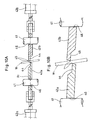
- Fig. 10A is a development of the cutter disclosed in the above publication, showing the relationship between the cutter arms and their cylinders.
- two arm pins 41 are shown. But this is merely because this figure is a development. The actual cutter has only one such pin 41.
- the cutter arms are designated by numerals 42a and 42b, the cylinders by 43a and 43b, the mating surfaces by 44, and the cutting edges by 45.
- the axes of the cylinders are present in the plane X1 including the mating surfaces 44 of the cutter arms 42a, 42b.
- the arm-closing forces generated by the cylinders 43a and 43b act on the respective cutter arms 42a and 42b along the plane X1.
- the cutter arms tend to pivot outwardly as shown in Fig. 10B.
- the cutter arms are repeatedly pivoted outwardly, it becomes increasingly difficult to smoothly cut the object W.
- the arm pin 41 is loosely inserted in pin holes 46 formed in the cutter arms 42a and 42b. That is, gaps are present between the pin 41 and the pin holes 46.
- the tips of the cutter arms 42a and 42b are pushed outwardly, so that the cutter arms 42a and 42b pivot outwardly within the range permitted by the gaps between the pin 41and the pin holes 46 as shown in Fig. 10B. Since the arm-closing forces generated by the cylinders act on the arms along the plane X1, they cannot prevent the cutter arms from pivoting. Since the tips of the cutter arms are pushed outwardly, gaps are present between the mating surfaces 44 and thus between the cutting edges 45 when cutting the object W. This makes it difficult to cut the object W cleanly.
- the cutter arms 42a and 42b pivot outwardly about the pin 41, as shown in Fig. 11, the cutter arms are pressed hard against each other at their ends, shown at P1.
- the cutter arms 42a and 42b are also pressed hard against the side plates 47 of the bracket at points P2.
- the frictional resistance between the cutter arms and between the cutter arms and the side plates of the bracket hampers smooth pivoting motion of the cutter arms 42a and 42b in the closing directions.
- the force from the cylinders acts on the arm pin 41 at its longitudinal center and may deflect and in the worst case break the pin.
- Chips as well as a soft or thick object W to be cut tend to get stuck between the mating surfaces 44, thus hampering smooth cutting, or causing outward deformation of the tips of the arms 42a and 42b.
- pads or guide rails are provided on the outer sides of the cutter arms to prevent the arms from pivoting outwardly. But such extra members add to the number of parts and thus the cost of the cutter.
- each cylinder has its body connected to the movable bracket and the piston rod to one of the cutter arms.
- the piston rods protrude from the movable bracket.
- the piston rods tend to be damaged by hitting against obstacles.
- An object of the invention is to provide a demolition cutter in which the cylinders are arranged such that pushing force from the cylinders can minimize inclination of the cutter arms and outward deformation of the tips of the cutter arms when the cylinders are extended to close the cutter arms, thereby eliminating any gap between the mating surfaces of the cutter arms so that an object to be cut can be cut smoothly.
- a second object of the invention is to provide a compact demolition cutter which prevents damage to the piston rods of the cylinders for opening and closing the cutter arms, and which ensures smooth demolition work.
- a demolition cutter comprising a stationary bracket adapted to be connected to an arm of a construction machine, a movable bracket rotatably coupled to the stationary bracket and including a pair of opposed side plates, an arm pin extending between the pair of side plates, a pair of cutter arms pivotally mounted on the arm pin so as to be pivotable between an open position and a closed position, and a pair of cylinders each connected to one of the cutter arms, the stationary bracket carrying a rotary joint, the cylinders being extended and retracted by supplying pressure oil into the cylinders through the rotary joint, thereby pivoting the cutter arms between the open and closed positions, the arms having mating surfaces that are superposed on each other and formed with cutting edges that are configured to cross each other when the arms are pivoted toward the closed position, thereby cutting an object sandwiched therebetween, the cylinders having a central axis, at least one of the central axes of the cylinders being offset in the direction of the axis of the arm pin from the plane
- the pushing force from the cylinders act on the cutter arms parallel to the mating surfaces along planes offset from the mating surfaces.
- the pushing force from the cylinder serves to correct the orientation of the arms, that is, prevent the cutter arms from inclining outwardly. This prevents formation of a gap between the mating surfaces of the cutter arms, which in turn keeps high cutting force. An object can thus be cut smoothly.
- both axes of the two cylinders are offset from the plane including the mating surfaces. In another arrangement, only one of the axes of the two cylinders is offset. In either arrangement, the plane including the axes of the two cylinders intersects the plane including the mating surfaces.
- the former plane is inclined relative to the latter plane.
- the arm pin Since the force from the cylinders acts on the arm pin at points offset from its longitudinal center toward its ends, the arm pin is less likely to be deflected. Also, the cutter arms are less likely to be pressed hard against each other at their rear ends or against the side plates of the bracket. This keeps the rotational resistance small, so that the cutter arms can be closed smoothly.
- the cutter arms each include a gripper portion for gripping, in cooperation with the other gripper portion, an object to be dismantled.
- an object to be dismantled such as reinforciong steel or panels, they can be sheared, crushed, or moved to a position where they can be more easily cut, and cut.
- each of the cylinders comprises a cylinder body connected to one of the cutter arms, and a piston received in the cylinder body and including a piston rod having a rear end thereof connected to the movable bracket, the piston defining a front chamber and a rear chamber in the cylinder body in front and back thereof, the piston rod being formed with a first oil passage communicating with the front chamber and a second oil passage communicating with the rear chamber, the rotary joint including a rotary cylinder secured to the movable bracket and formed with a pair of first oil ports each facing one of the cylinders, and a pair of second oil ports each facing one of the cylinders, the first and second oil passages formed in the piston rod of each of the cylinders being connected to one of the first oil ports and one of the second oil ports, respectively, through hydraulic hoses.
- the hoses are also covered by the movable bracket.
- the hoses will never be caught by the objects to be dismantled, or otherwise get in the way of dismantling work. They will never be damaged either. This ensures efficient dismantling work.
- the demolition cutter of the first embodiment includes a stationary bracket 1 adapted to be detachably mounted to the free end of an arm of a construction machine such as a hydraulic shovel.
- the bracket 1 has a support plate 2 on which is rotatably supported a coupling plate 4 through a bearing 5 so as to oppose the support plate 2.
- the coupling plate 4 supports a movable bracket 3.
- the movable bracket 3 is thus rotatable relative to the stationary bracket 1.
- the movable bracket 3 is a box comprising a pair of side plates 6 extending from the side edges of the coupling plate 4 and a pair of end plates 7 extending from the end edges of the coupling plate 4.
- An arm pin 8 extends between the side plates 6 near their free ends.
- a pair of cutter arms 9a and 9b have their rear ends mounted on the arm pin 8 so as to be pivotable about the pin 8 between open and closed positions.
- the cutter arms 9a and 9b are each formed with a coupling piece 10 at its outer portion.
- the cutter arms 9a and 9b have mating surfaces 11 adapted to be superposed on each other when the cutter arms are closed.
- the mating surfaces 11 have cutting edges 12.
- the cutter arms 9a and 9b have gripper portions 13 at their tips.
- Cylinders 14a and 14b are connected to the respective coupling pieces 10 of the cutter arms 9a and 9b.
- the cylinders 14a and 14b each comprise a cylinder body 15, and a piston 16 slidably mounted in the cylinder body 15 to define front and rear chambers 17 and 18 in the cylinder body 15 as shown in Fig. 7.
- the piston 16 has a piston rod 19 slidably extending into the cylinder body 15 and is formed with a first oil passage 20 communicating with the front chamber 17 and a second oil passage 21 communicating with the rear chamber 18.
- the oil passages 20 and 21 have hose connecting ports 20a, 21a that open at the outer periphery of the piston rod 19 near its rear end.
- Each of the cylinders 14a and 14b has a mounting piece 22 provided on a head cover of the cylinder body 15 and coupled to the coupling piece 10 of the corresponding arm 9a, 9b through a pin 23. Its piston rod 19 is coupled at its rear end to one of two connecting pieces 24 secured to the front side of the coupling plate 4 by means of a pin 25.
- the cylinder body 15 is axially movable relative to the piston 16.
- the cylinders 14a and 14b are structured such that when their respective cylinder body 15 is extended to its limit, the rear end of the cylinder body 15 is still disposed between the side plates 6 of the movable bracket 3.
- the support plate 2 of the stationary bracket 1 supports a rotary joint 26 through which pressure oil is supplied into the cylinders 14a and 14b and oil is discharged from the cylinders 14a and 14b into a tank, not shown.
- the rotary joint 26 comprises a joint body 27 fixed to the support plate 2 of the stationary bracket 1 (see Fig. 2), and a rotary cylinder 28 rotatable relative to the joint body 27.
- a first passage 29 and a second passage 30 are formed in the joint body 27.
- the rotary cylinder 28 is formed with two first oil ports 31 communicating with the first passage 29, and two second oil ports 32 communicating with the second passage 30.
- each of the first oil ports 31 and each of the second oil ports 32 face one of the cylinders 14a and 14b.
- each of the first oil ports 31 and each of the second oil ports 32 are connected to the hose-connecting port 20a and 21a of the first and second oil passages 20 and 21 of one of the cylinders 14a and 14b through hydraulic hoses 33 and 34, respectively.
- Each of the hoses 33 and 34 forms a loop in front of the rotary joint 26.
- the loops serve to absorb any tensile and other forces applied to the hoses 33 and 34 when the cylinders 14a and 14b pivot about the pin 25 due to extension or retraction of the cylinders, thereby keeping the hoses 33 and 34 from being subjected to any undue external force.
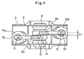
- Fig. 5 is a development of the cutter of Fig. 1, showing the relationship between the cutter arms 9a, 9b and the cylinders 14a, 14b. From Fig. 5, the cutter appears to have two arm pins 8. But this is merely because Fig. 5 is a development. The actual cutter has only one such arm pin 8. As shown in Fig. 5, the mating surfaces 11 are in a single plane X0. The axes of the cylinders 14a and 14b are offset outwardly by a distance L1 from the plane X0 in opposite directions to each other. The offset distance L1 is adjusted according to the required cutting force and the shape of the arms.
- the arms 9a and 9b are less likely to pivot outwardly, the arms 9a and 9b are less likely to be pressed hard against each other at the inner surfaces of their rear ends, or against end faces of bearings 8a for the arm pin 8 which are mounted to the side plates 6 of the movable bracket 3. Thus, the arms 9a and 9b can be pivoted smoothly in the closing directions without encountering any significant resistance.
- the pushing forces F0 from the cylinders 14a and 14b act on the arm pin 8 at its portions offset toward its ends from its longitudinal center.
- the arm pin 8 is thus less likely to be deflected by such forces and thus is less likely to be broken, even if its diameter is relatively small.
- the gripper portions 13 at the tips of the arms 4a and 4b are used to grip and tear or crush the objects to be dismantled when the arms are closed.
- the cylinders 14a and 14b are extended and retracted by selectively supplying pressure oil into the first and second passages 29 and 30 formed in the rotary joint 26 as shown in Fig. 7.
- the piston rods 19 of the cylinders 14a and 14b are connected to the movable bracket 3 at their rear ends, and the cylinder bodies 15 are connected to the respective arms 9a and 9b, the cylinder bodies 15 are moved axially by supplying pressure oil.
- the cylinder bodies 15 are extended to their limit, the rear ends of the cylinder bodies 15 are still inside of the movable bracket 3.
- the piston rods 19 are always covered by the movable bracket 3.
- the piston rods 19 will therefore never be damaged by obstacles by hitting against them during use.
- the piston rods 19 are each formed with the first oil passage 20, which communicates with the front chamber 17 defined in front of the piston, and the second oil passage 21, which communicates with the rear chamber 18, and the hose-connecting ports 20a and 21a of the first and second oil passages 20 and 21 are connected to the first and second oil ports 31 and 32 of the rotary joint 26 through the hydraulic hoses 33 and 34, respectively, the hoses 33 and 34 are always covered by the movable bracket 3.
- the hoses will never be caught on the objects to be dismantled or otherwise get in the way of dismantling work. They will never be damaged either.
- the rotary joint 26 is formed with the first and second oil ports 31 and 32 so as to face the cylinders 14a and 14b, the ends of the hydraulic hoses 33 and 34 are disposed between the rotary joint 26 and the piston rods 19 of the cylinders 14a and 14b. This makes it possible to reduce the distance between the side plates 6 of the movable bracket 3.
- the cylinders 14a and 14b are arranged such that their axes are offset outwardly from the plane X0 containing the mating surfaces 11 in opposite directions to each other. But instead, as shown in Fig. 8, only one of the cylinders 14a and 14b may be arranged so that its axis is offset outwardly from the plane X0.
- the arms 9a and 9b may be individually supported on two separate pins.
- Fig. 9A and 9B show the demolition cutter of the third embodiment.
- This embodiment differs from the first embodiment (Fig. 1) in that the cylinder coupling pieces 10 of this embodiment are provided closer to the tips of the arms 9a and 9b than the coupling pieces 10 of the first embodiment to such an extent that the cylinders 14a and 14b are connected to the arms 9a and 9b at points forwardly of the arm pin 8 even when the arms are fully opened as shown in Fig. 9A.
- the arms are less likely to pivot outwardly while cutting an object by extending the cylinders.
- no gap will be formed between the mating surfaces during cutting, which allows smoother cutting.
- the cutter according to the invention is thus made up of a smaller number of parts and thus is less costly.
- the pushing force from the cylinders is applied to the arm pin at points offset from its longitudinal center toward its ends.
- the arm pin is thus less likely to be deflected by this force. This makes it possible to reduce the diameter of the arm pin.
- the piston rods are each formed with the first oil passage, which communicates with the front chamber, and the second oil passage, which communicates with the rear chamber, the hydraulic hoses connecting the respective oil passages to the first and second oil ports of the roatary joint are always covered by the movable bracket.
- the hoses will never be caught on objects to be dismantled or otherwise get in the way of dismantling work. They will never be damaged either.
- the rotary cylinder of the rotary joint is formed with the first and second oil ports so as to face the cylinders, ends of the hydraulic hoses connected to the oil ports are also provided on both sides of the rotary joint. This makes it possible to reduce the distance between the side plates of the movable bracket.
Landscapes
- Engineering & Computer Science (AREA)
- Mechanical Engineering (AREA)
- Architecture (AREA)
- Structural Engineering (AREA)
- Civil Engineering (AREA)
- Mining & Mineral Resources (AREA)
- General Engineering & Computer Science (AREA)
- Chemical & Material Sciences (AREA)
- Chemical Kinetics & Catalysis (AREA)
- Electrochemistry (AREA)
- Working Measures On Existing Buildindgs (AREA)
- Shearing Machines (AREA)
Applications Claiming Priority (5)
| Application Number | Priority Date | Filing Date | Title |
|---|---|---|---|
| JP2002228410 | 2002-08-06 | ||
| JP2002228410A JP4166052B2 (ja) | 2002-08-06 | 2002-08-06 | 解体切断機 |
| JP2002242418A JP4213927B2 (ja) | 2002-08-22 | 2002-08-22 | 解体切断機 |
| JP2002242418 | 2002-08-22 | ||
| PCT/JP2003/009890 WO2004016881A1 (fr) | 2002-08-06 | 2003-08-04 | Machine de démolition et de coupe |
Publications (2)
| Publication Number | Publication Date |
|---|---|
| EP1548206A1 true EP1548206A1 (fr) | 2005-06-29 |
| EP1548206A4 EP1548206A4 (fr) | 2011-02-23 |
Family
ID=31890513
Family Applications (1)
| Application Number | Title | Priority Date | Filing Date |
|---|---|---|---|
| EP03788031A Withdrawn EP1548206A4 (fr) | 2002-08-06 | 2003-08-04 | Machine de demolition et de coupe |
Country Status (4)
| Country | Link |
|---|---|
| US (1) | US7237738B2 (fr) |
| EP (1) | EP1548206A4 (fr) |
| AU (1) | AU2003252609A1 (fr) |
| WO (1) | WO2004016881A1 (fr) |
Families Citing this family (4)
| Publication number | Priority date | Publication date | Assignee | Title |
|---|---|---|---|---|
| ITTO20080074A1 (it) * | 2008-01-31 | 2009-08-01 | Corimag S R L | Attrezzatura frantumatrice per operazioni di demolizione o simili. |
| JP4650571B2 (ja) * | 2009-01-05 | 2011-03-16 | コベルコ建機株式会社 | 油圧破砕機 |
| DE102009012050A1 (de) * | 2009-03-06 | 2010-09-09 | Lst Gmbh | Anbaugerät |
| CN110185283A (zh) * | 2019-04-25 | 2019-08-30 | 北京工业大学 | 一种采用活动刃口的钳剪抱多功能救援属具 |
Family Cites Families (5)
| Publication number | Priority date | Publication date | Assignee | Title |
|---|---|---|---|---|
| US3294131A (en) * | 1966-01-12 | 1966-12-27 | Beloit Corp | Shear clamping mechanism |
| JPH0340504Y2 (fr) * | 1986-09-25 | 1991-08-26 | ||
| JPH0340504A (ja) | 1989-07-06 | 1991-02-21 | Matsushita Electric Ind Co Ltd | 包絡線検波回路 |
| US5060378A (en) * | 1989-12-15 | 1991-10-29 | Labounty Manufacturing, Inc. | Demolition tool for a hydraulic excavator |
| JP2556664B2 (ja) | 1994-04-18 | 1996-11-20 | 大淀ヂ−ゼル株式会社 | 鋼材剪断機 |
-
2003
- 2003-08-04 EP EP03788031A patent/EP1548206A4/fr not_active Withdrawn
- 2003-08-04 US US10/523,361 patent/US7237738B2/en not_active Expired - Fee Related
- 2003-08-04 WO PCT/JP2003/009890 patent/WO2004016881A1/fr not_active Ceased
- 2003-08-04 AU AU2003252609A patent/AU2003252609A1/en not_active Abandoned
Non-Patent Citations (2)
| Title |
|---|
| No further relevant documents disclosed * |
| See also references of WO2004016881A1 * |
Also Published As
| Publication number | Publication date |
|---|---|
| US7237738B2 (en) | 2007-07-03 |
| EP1548206A4 (fr) | 2011-02-23 |
| US20060032955A1 (en) | 2006-02-16 |
| WO2004016881A1 (fr) | 2004-02-26 |
| AU2003252609A1 (en) | 2004-03-03 |
Similar Documents
| Publication | Publication Date | Title |
|---|---|---|
| US5146683A (en) | Reinforcement cutter | |
| US5044569A (en) | Rock and coral demolition tool | |
| US4890798A (en) | Structure crushing equipment | |
| US7255295B2 (en) | Multiple tool attachment system with rotational coupling | |
| US5704560A (en) | Concrete crusher with cutting shears | |
| EP0435702B1 (fr) | Outil de démolition pour une pelle excavatrice | |
| KR102183609B1 (ko) | 측방향 스태빌라이저를 통합한 액추에이터 핀 | |
| CA2387725C (fr) | Systeme de fixation d'outils multiple | |
| US7954742B2 (en) | Dual purpose adapter for a multiple tool attachment system | |
| EP2204502B1 (fr) | Broyeur hydraulique | |
| EP0678354B1 (fr) | Dispositif pour couper des matériaux en acier | |
| WO2008127859A1 (fr) | Outil d'excavation défonceur | |
| US20090145274A1 (en) | Demolition shears | |
| US7237738B2 (en) | Demolishing and cutting machine | |
| US20070145171A1 (en) | Rebar cutting shears | |
| JP5322557B2 (ja) | 建設機械のアーム | |
| JP4009395B2 (ja) | 高信頼性プレ−ト切断特性を有する大型解体剪断機 | |
| JP3667412B2 (ja) | 破砕機のアーム同調機構 | |
| JP4166052B2 (ja) | 解体切断機 | |
| JPH0211709B2 (fr) | ||
| JPH0544445Y2 (fr) | ||
| EP3622122B1 (fr) | Système de burin pour excavatrice | |
| KR20230129677A (ko) | 복합 기능을 가지는 건설기계용 어태치먼트 | |
| JP4213927B2 (ja) | 解体切断機 | |
| AU2024209959A1 (en) | Cutting device and support for same |
Legal Events
| Date | Code | Title | Description |
|---|---|---|---|
| PUAI | Public reference made under article 153(3) epc to a published international application that has entered the european phase |
Free format text: ORIGINAL CODE: 0009012 |
|
| 17P | Request for examination filed |
Effective date: 20050302 |
|
| AK | Designated contracting states |
Kind code of ref document: A1 Designated state(s): AT BE BG CH CY CZ DE DK EE ES FI FR GB GR HU IE IT LI LU MC NL PT RO SE SI SK TR |
|
| AX | Request for extension of the european patent |
Extension state: AL LT LV MK |
|
| DAX | Request for extension of the european patent (deleted) | ||
| A4 | Supplementary search report drawn up and despatched |
Effective date: 20110125 |
|
| 17Q | First examination report despatched |
Effective date: 20110530 |
|
| STAA | Information on the status of an ep patent application or granted ep patent |
Free format text: STATUS: THE APPLICATION IS DEEMED TO BE WITHDRAWN |
|
| 18D | Application deemed to be withdrawn |
Effective date: 20111011 |