EP1548251B1 - Zweitakt-Motor mit interner Verbrennung und Gleichdruckturboaufgeladung mit 13 Zylindern in einer einzigen Reihe - Google Patents
Zweitakt-Motor mit interner Verbrennung und Gleichdruckturboaufgeladung mit 13 Zylindern in einer einzigen Reihe Download PDFInfo
- Publication number
- EP1548251B1 EP1548251B1 EP04388090A EP04388090A EP1548251B1 EP 1548251 B1 EP1548251 B1 EP 1548251B1 EP 04388090 A EP04388090 A EP 04388090A EP 04388090 A EP04388090 A EP 04388090A EP 1548251 B1 EP1548251 B1 EP 1548251B1
- Authority
- EP
- European Patent Office
- Prior art keywords
- cylinder
- cylinders
- firing
- internal combustion
- engine
- Prior art date
- Legal status (The legal status is an assumption and is not a legal conclusion. Google has not performed a legal analysis and makes no representation as to the accuracy of the status listed.)
- Expired - Lifetime
Links
Images


Classifications
-
- F—MECHANICAL ENGINEERING; LIGHTING; HEATING; WEAPONS; BLASTING
- F02—COMBUSTION ENGINES; HOT-GAS OR COMBUSTION-PRODUCT ENGINE PLANTS
- F02B—INTERNAL-COMBUSTION PISTON ENGINES; COMBUSTION ENGINES IN GENERAL
- F02B75/00—Other engines
- F02B75/16—Engines characterised by number of cylinders, e.g. single-cylinder engines
- F02B75/18—Multi-cylinder engines
- F02B75/20—Multi-cylinder engines with cylinders all in one line
-
- F—MECHANICAL ENGINEERING; LIGHTING; HEATING; WEAPONS; BLASTING
- F02—COMBUSTION ENGINES; HOT-GAS OR COMBUSTION-PRODUCT ENGINE PLANTS
- F02B—INTERNAL-COMBUSTION PISTON ENGINES; COMBUSTION ENGINES IN GENERAL
- F02B75/00—Other engines
- F02B75/02—Engines characterised by their cycles, e.g. six-stroke
- F02B2075/022—Engines characterised by their cycles, e.g. six-stroke having less than six strokes per cycle
- F02B2075/025—Engines characterised by their cycles, e.g. six-stroke having less than six strokes per cycle two
-
- F—MECHANICAL ENGINEERING; LIGHTING; HEATING; WEAPONS; BLASTING
- F02—COMBUSTION ENGINES; HOT-GAS OR COMBUSTION-PRODUCT ENGINE PLANTS
- F02B—INTERNAL-COMBUSTION PISTON ENGINES; COMBUSTION ENGINES IN GENERAL
- F02B75/00—Other engines
- F02B75/16—Engines characterised by number of cylinders, e.g. single-cylinder engines
- F02B75/18—Multi-cylinder engines
- F02B2075/1804—Number of cylinders
- F02B2075/1852—Number of cylinders thirteen
-
- F—MECHANICAL ENGINEERING; LIGHTING; HEATING; WEAPONS; BLASTING
- F02—COMBUSTION ENGINES; HOT-GAS OR COMBUSTION-PRODUCT ENGINE PLANTS
- F02B—INTERNAL-COMBUSTION PISTON ENGINES; COMBUSTION ENGINES IN GENERAL
- F02B37/00—Engines characterised by provision of pumps driven at least for part of the time by exhaust
Definitions
- the present invention relates to a two-stroke constant-pressure turbocharged internal combustion engine having 13 cylinders in a single row, at least one exhaust gas receiver, at least two turbochargers, and a scavenge air system with at least one elongated scavenge air receiver, each cylinder having a scavenge air inlet connected to the scavenge air receiver and an exhaust passage leading into the at least one exhaust gas receiver, said turbochargers being connected with the exhaust gas receiver on their turbine side and with the scavenge air system on their compressor side, which engine has a firing sequence (n1 - n13) of the engine cylinders C1-C13.
- EP 0 713 000 Al describes a two-stroke internal combustion engine having 13 cylinders in a single row, which engine has a firing sequence of the engine cylinders C1-C13Vibrations in the mechanical parts of the engine and structures connected to the engine are described, such as torsional vibrations in the shafting system, vibrations in the engine frame, and vibrations in the ship hull or superstructure.
- torsional vibrations in the shafting system vibrations in the engine frame, and vibrations in the ship hull or superstructure.
- EP 1 333 192 A2 describes a method of determining firing angles in four-stroke V-engines, and in two-stroke in-line engines having 7, 8 or 9 cylinders. The method determines firing angles that minimize an unbalanced couple acting as vibrating force.
- the types of vibrations mentioned are vibration of the engine main body, torsional vibrations in the engine shaft, and vibrations in pipings etc. connected to the engine. These vibrations are all in steel structures, viz, vibrations of mechanical systems. There is no indication of vibrations in other structures than steel based structures.
- Constant-pressure turbocharging of an internal combustion engine is based on the principle that the exhaust gas flow pulses from the individual cylinders are equalized by passing the exhaust gas from the cylinders out through the associated exhaust passage to a common exhaust receiver which is an elongate pressure vessel of a sufficiently large volume to allow some expansion of the many high intensity gas flow pulses from the cylinders into a common gas flow at an even pressure.
- the turbine part of the turbochargers receives exhaust gas at a constant pressure when the engine load is constant, and this increases the efficiency of the turbochargers and results in a constant supply of inlet air from the compressor part of the turbochargers to the scavenge air system on the inlet side of the engine cylinders.
- Pressure fluctuations in the exhaust gas receiver can cause fluctuations in the power of the turbochargers and thus uneven and varying charging air deliveries to the charging air system.
- the supply of scavenge air to the inlet side of the engine influences the filling of the cylinders with charging air and thus the combustion process in the cylinders and the power developed at the combustions.
- the in-line engine with 13 cylinders has a long length and thus a long scavenge air receiver.
- the pressure variations in the charging air supplied from the turbochargers can to some degree cause pressure variations in the scavenge air receiver.
- larger pressure fluctuations in the scavenge air receiver are created by the pattern in which the cylinders consume scavenge and charging air from the scavenge air receiver.
- the object of the present invention is to minimize or avoid fluctuations in fuel dosage to the engine cylinders caused by variations in the filling of the cylinders with charging air, when the engine is running at constant load.
- the two-stroke constant-pressure turbocharged internal combustion engine is characterized in that the thirteen cylinders have a firing sequence (n1 - n13) so that at least the following three requirements a) to c) are met for the 4 th order gas pulsation
- the firing sequence complies with these requirements the primary source for formation of pressure fluctuations in the scavenge air receiver has been minimized to such a low level that the fuel dosing to the cylinders is unaffected by scavenge air pressure fluctuations.
- the firing sequences fulfilling the requirements result in that the cylinders consume scavenge and charging air from the scavenge air receiver in sequences that do not create too large pressure fluctuations of the air in the scavenge air receiver.
- the thirteen cylinders have a firing sequence (n1 - n13) so that the following requirement d) is also met
- a long in-line engine as a 13 cylinder two-stroke engine is typically used as a propulsion engine in a ship.
- the advantages obtained by designing the firing sequence in accordance with requirements a) to c) are further enhanced by also making requirement d) be fulfilled.
- Requirement d) furthermore provides the advantage that the so-called nick-moments will be diminished.
- Nick-moments are a weighted summation over the cylinders of the vertical forces acting at the tie rods and at the main bearings. The nick-moments tend to induce an undesired vibration of the engine and ship hull in the vertical plane.
- the thirteen cylinders have a firing sequence (n1 - n13) so that the following requirement e) is also met
- the firing sequence can be even in the sense that the turning angle of the crankshaft between the firing of two consecutive cylinders is 360°/13. This fixed size angle is used for all cylinders in the engine. If there is a special problem in a particular engine installation it is also possible to fine-tune the vibration pattern by using a firing sequence which is uneven in the sense that the turning angle of the crankshaft between the firing of at least two pairs of consecutively firing cylinders is different from 360°/13.
- Fig. 1 is seen the cross-section through a large two-stroke constant-pressure turbocharged internal combustion engine of the crosshead type, having 13 cylinders.
- the engine can e.g. be of the make MAN B&W Diesel and the type MC or ME, or of the make Wartsilä of the type Sulzer RT-flex or Sulzer RTA, or of the make Mitsubishi Heavy Industries.
- the cylinders can have a bore in the range of e.g. 60 to 120 cm, preferably from 80 to 120 cm.
- the engine can e.g. have a power in the range of 3000 to 8000 kW per cylinder, preferably from 4000 to 7000 kW per cylinder, and suitably at least 5000 kW per cylinder.
- Each cylinder C1-C13 typically has a cylinder liner 1 with a row of scavenge air ports 2 in its lower end and a cylinder cover 3 with an exhaust valve 4 located in the top of the cylinder.
- a piston 5 is mounted on a piston rod 6, which via a crosshead 7 and a connecting rod 8 is connected with a crank pin 9 on a crankshaft 10.
- the crankshaft journal 11 is located in a main bearing mounted in a bedplate 12.
- the crosshead is supported in the transverse direction by guide shoes 13 sliding on vertically extending guide planes.
- the guide planes are fixed to the stationary A-frame 14 of the engine.
- a cylinder section 15 is mounted on top of the A-frame.
- the cylinder cover 3 is fixed to the cylinder section by cover studs 16.
- Tie-rods 17 extend from the cylinder section down to the bedplate and they fix the cylinder section 15 to the bedplate 12.
- An exhaust gas duct 18 extends from the individual cylinder in the area of the exhaust valve and opens out into an exhaust gas receiver 19 that is common to a number of cylinders.
- the engine may have only a single exhaust gas receiver which is common to all cylinders, or it can have a plurality of exhaust gas receivers, such as two or three, located end-to-end in extension of each other and typically interconnected through gas flow passages.
- the exhaust gas receiver is a pressure vessel with a circular cylindrical cross-section.
- the exhaust gas duct 18 is extending into the exhaust receiver 19 and delivers the exhaust gas from the pertaining combustion chamber when the exhaust valve is open.
- pressure variations caused by the exhaust gas pulses emitted from the exhaust gas ducts are equalized to a more even pressure.
- turbochargers 20 are connected to the exhaust gas receiver 19 in such a manner that the exhaust gas can flow via exhaust passages 21 through the turbine part 22 of the turbocharger where it acts as a drive medium for the turbine wheel, which is mounted on a drive shaft for a compressor wheel located in a compressor part 23 of the turbocharger.
- the compressor part 23 can deliver compressed air in direction of art row A via an air flow passage 24 and possibly an inlet air cooler 25 to a scavenge air system 26.
- the scavenge air system comprises at least one scavenge air receiver 27 common to several or all cylinders, and for the individual cylinder a flow passage 28 that connects an inlet air chamber 29 with the scavenge air receiver so that inlet air can flow in direction of arrow B to fill the inlet air chamber with air to be consumed by the cylinder.
- the scavenge air receiver is a pressure vessel with a cylindrical shape that is circular in cross-section.
- Check-valves 31 are provided at the air inlets in the lower portion of scavenge air receiver 27.
- the inlet air is called both scavenge air and charging air.
- the inlet air is one and the same. However, for a two-stroke engine there is needed inlet air to scavenge (clean) the combustion chamber for combustion products while the exhaust valve is open and inlet air to charge the cylinder with air for the next combustion process after closure of the exhaust valve.
- the inlet air chamber 29 surrounds the lower portion of cylinder liner 1 with the scavenge air ports 2.
- piston 5 is moved in downward direction until it is positioned in the lowermost part of cylinder liner at the bottom dead centre position in which the upper surface of the piston is located below scavenge air ports 2.
- air from inlet air chamber 29 flows into the cylinder and causes a pressure drop in said chamber and also in the scavenge air receiver in the local area near flow passage 28 leading into the cylinder.
- the air consumptions and associated local pressure drops in the scavenge air receiver occur at the flow passages 28 that are distributed along the length of the scavenge air receiver.
- the cylinders consume air in a sequential manner at points in time that depend on the firing sequence of the engine. As the delivery of inlet air to the cylinders varies both in time and place, the air inside the scavenge air receiver may be made to fluctuate.
- the natural frequencies of longitudinal gas pressure waves inside the scavenge air receiver depend, among other things, on the length of the receiver.
- the scavenge air receiver illustrated in Fig. 5 is common to all cylinders on the engine, and it consequently extends along the complete length of the engine.
- the lowest natural frequency of the air fluctuations in the scavenge air receiver corresponds to so-called 1 st mode gas pulsations, in which the pressures at the receiver ends are in counter-phase and the largest velocity changes occur in the middle of the receiver.
- the 1 st mode gas pulsation is illustrated by the curve a in Fig. 5.
- the 2 nd mode gas pulsation is illustrated by the curve b in Fig. 5. It appears that the 1 st mode gas pulsation has a single node 32, the 2 nd mode gas pulsation two nodes 32, and so forth with one additional node for every increase of the mode number.
- the ability of the sequential consumption of air to excite gas dynamic oscillations in the scavenge air receiver depends on the firing sequence of the engine and the current engine speed. If the frequency of the pressure waves coincides with a natural frequency for a specific mode of gas pulsations, rather large air pressure fluctuations can occur. These undesired pressure fluctuations may affect the filling of the cylinders, in particular the cylinders located at the largest distances from the nodes 32 in the relevant vibration order.
- the sequence in which the cylinders consume air from the scavenge air receiver is such that the variations in filling of cylinders due to scavenge air pulsations are so small that they do not cause disturbing adjustments in the fuel setting for the cylinders.
- the cylinders C1 to C13 fire in the sequence 1 4 11 10 6 2 8 12 7 3 5 13 9.
- the firing sequence is implemented in the engine by making the crankshaft 10 with crank throws 33 pointing in the angular pattern required for obtaining the firing sequence.
- the firing sequence is determined by the design of the crankshaft.
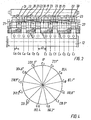
- Fig. 3 illustrates the pattern required for firing sequence No. 1 as even firing sequence, viz. a firing sequence with a regular (even) angular interval of 360°/13 between the firings.
- Each crank throw 33 comprises two crank arms 34 and the crank pin 9, and the crank shaft journals 11 join the crank throws into a complete crank shaft.
- the crankshaft journals are aligned along a centre line 35 of the crankshaft and they are supported in main bearings in bedplate 12.
- the crankshaft can suitably be divided into two sections in order to reduce the weight of the individual section.
- crankshaft joint between other cylinders, such as cylinders C6 and C7.
- the engine can be an electronically controlled engine without a camshaft for activating fuel pumps and exhaust valves, e.g. an engine of the type ME. If the engine is of a traditional type with a camshaft, the camshaft can be driven from the crankshaft via a chain drive or a gearing, which suitably can be located between the cylinders separated by the larger distance 12.
- Fig. 4 The respective angles between the crank throws 33 of the crankshaft of Fig. 3 are also illustrated in Fig. 4. It is also possible to use irregular firing sequences, viz. a firing sequence that is uneven in the sense that the angular interval between the firings of at least two pairs, and possibly several pairs, of consecutively firing cylinders deviates from 360°/13. A deviation of only a few degrees can result in a different vibration pattern in the engine. Such irregular firing sequences can be useful for fine tuning of the resulting vibration characteristics of the engine. With respect to gas pulsations in the scavenge air receiver it is the firing sequence as such that is of importance for obtaining the advantageously low level of gas pulsations and not whether the firing sequence is regular or irregular.
- the calculations are in the following exemplified with respect to the 13 cylinder engine illustrated in Fig. 2.
- the total length between the vertical centre lines of cylinders C1 and C13 is 22.3 m, and a chain drive is located between cylinders C7 and C8.
- Firing angles for cylinders C1 to C13 0°, 138.5°, 249.2°, 27.7°, 276.9°, 110.8°, 221.5°, 166.2°, 332.3°, 83.1°, 55.4°, 193.8°, and 304.6°.
- the position of the cylinder is calculated as the distance of the cylinder Cn from the cylinder C1 in the longitudinal direction of the engine divided by the total distance between the centre lines of cylinders C1 and C13.
- F(n) is consequently equal to 1 - 2 x (distance of cylinder Cn from cylinder C1)/(total distance from cylinder C1 to cylinder C13).
- the resulting length of the vector is 0.89, which is well below the value of 1.8.
- the resulting length of the vector is 0.46, which is well below the value of 1.8.
- F(n) F(n-1) + ((distance from the centre line of cylinder C n-1 to the centre line of cylinder C n )/(nominal distance between cylinders)).
- the nominal distance between cylinders is the horizontal distance between the vertical centre lines of two adjacent cylinders having no chain drive in between the cylinders. When the engine is provided with a chain drive for a camshaft, this chain drive is typically located at the middle of the engine.
- the nominal distance between cylinders can consequently in the ordinary case be identified as the distance between cylinders in the end area of the engine, such as the distance between cylinders C1 and C2.
- the resulting length of the vector is 1.245, which is well below the value of 2.5.
- the resulting length of the vector is 2.178, which is well below the value of 6.0.
- Fig. 6 The forces producing the nick moments are illustrated in Fig. 6.
- the upwards directed force on the cylinder cover results in upwards directed forces 36 in the four tie-rods that connect the cylinder portion with the bedplate, and at the same time the main bearing associated with cylinder 13 is subjected to a downwards directed thrust force 37. Similar forces occur at the other cylinders as they fire.
- These vertically acting forces produce the so-called nick moments that act on the engine and the engine supporting structure in a manner that can introduce vertical vibrations.
- These vertical vibrations can have negative influences, in particular when the engine is a main propulsion engine in a container ship, because the nick moments will induce hull vibrations of a highly undesired character.
- the engine according to the present invention has firing sequences that limit the size of the nick moments, and the engine is consequently particularly suitable for use in a container ship which typically has a long hull and requires a main engine producing a very large power in order to propel the ship at the high speed required when transporting cargo of high value.
- the engine according to the present invention solves at the same time one of the major vibration problems pertaining to container ship propulsion.
- the engine according to the present invention is thus particularly suitable for use as a main propulsion engine in a container ship, and especially in a container ship having a capacity of at least 10.000 TEU, such as from 10.001 to 11.900 TEU or from 12.001 to 14.000 TEU or from more than 13.000 TEU, one TEU being the equivalent of a single 20' container.
- TEU is the standard measure for the capacity of a container ship.
- Table 1 presents relevant vibration values of some of the other above mentioned firing sequences.
- the firing sequences are numbered FS 1 etc in accordance with the numbering of the above mentioned sequences.
- the table states the vector lengths according to each of the requirements a) to e).
- the engine frame can be of any suitable shape, and the cylinder sections can be integrated in the frame.
- the scavenge air receiver - and possibly also the exhaust gas receiver - can have other cross-sectional shapes that the circular shape.
- the scavenge air system can include further elements than described, such as water mist collectors.
- the cylinders need not be numbered with C1 at the forward end of the engine and C13 at the aft end. They can equally well be numbered with C1 at the aft end and C13 at the forward end.
- the engine can be utilized as a stationary engine in a power plant.
- requirement a) can be Vgas(4) ⁇ 1.2 or Vgas(4) ⁇ 1.0.
- requirement b) can be limited to Vgas(5) ⁇ 1.2 or Vgas (5) ⁇ 1.0
- requirement c) can be limited to Vgas(6) ⁇ 1.2 or Vgas(6) ⁇ 1.0.
- Requirement d) can be limited to Vnick (1) ⁇ 1.5 or Vnick (1) ⁇ 1.3
- requirement e) can be limited to Vnick(2) ⁇ 3.0 or Vnick(2) ⁇ 2.5.
Landscapes
- Engineering & Computer Science (AREA)
- Chemical & Material Sciences (AREA)
- Combustion & Propulsion (AREA)
- Mechanical Engineering (AREA)
- General Engineering & Computer Science (AREA)
- Supercharger (AREA)
- Combined Controls Of Internal Combustion Engines (AREA)
- Electrical Control Of Ignition Timing (AREA)
- Output Control And Ontrol Of Special Type Engine (AREA)
Claims (8)
- Zweitaktmotor mit interner Verbrennung und Gleichdruckturboaufladung mit dreizehn Zylindern in einer einzigen Reihe, wenigstens einem Abgassammelbehälter (19), wenigstens zwei Turboladern (20) und einem Spülluftsystem (26) mit wenigstens einem länglichen Spülluftsammelbehälter (27), wobei jeder Zylinder einen mit dem Spülluftsammelbehälter (27)verbundenen Spüllufteinlass und einen in den wenigstens einen Abgassammelbehälter (19) führenden Auslasskanal (18) aufweist und die Turbolader (20) auf ihrer Turbinenseite mit dem Abgassammelbehälter (19) und auf ihrer Kompressorseite mit dem Spülluftsystem (26) verbunden sind, und wobei dieser Motor eine Zündfolge (n1 - n13) der Motorzylinder C1 bis C13 aufweist, dadurch ge- kennzeichnet, dass die dreizehn Zylinder eine Zündfolge (n1 - n13) aufweisen, so dass wenigstens die folgenden drei Anforderungen a) bis c) erfüllt werden,
für die Gaspulsation der 4. Ordnunga) b)
b) c)wobei n die Zylinderzahl ist, ϕn der Zündwinkel für Zylinder n ist, F(n) eine Gewichtungsfunktion ist, die in Bezug auf die Position des Zylinders zwischen F(1) = 1 bei Zylinder C1 und F(13) = -1 bei Zylinder C13 linear interpoliert wird, und ∥ die Länge des Vektors bezeichnet.
- Zweitaktmotor mit interner Verbrennung und Gleichdruckturboaufladung nach Anspruch 1, dadurch gekennzeichnet, dass die dreizehn Zylinder eine Zündfolge (n1 - n13) aufweisen, so dass auch die folgende Anforderung (d) erfüllt wird,d)wobei n die Zylinderzahl ist, ϕn der Zündwinkel für Zylinder n ist, F(n) eine Gewichtungsfunktion ist, welche F(1) = 0 bei Zylinder C1 und F(n) = F(n -1) + ((Abstand von der Mittellinie von Zylinder Cn-1 zur Mittellinie von Zylinder Cn)/(Nennabstand zwischen Zylindern)) ist, und ∥ die Länge des Vektors bezeichnet.

- Zweitaktmotor mit interner Verbrennung und Gleichdruckturboaufladung nach Anspruch 1 oder 2, dadurch gekennzeich- net, dass die dreizehn Zylinder eine Zündfolge (n1 - n13) aufweisen, so dass auch die folgende Anforderung (e) erfüllt wird,e)wobei n die Zylinderzahl ist, ϕn der Zündwinkel für Zylinder n ist, F(n) eine Gewichtungsfunktion ist, welche F(1) = 0 bei Zylinder C1 und F(n) = F(n -1) + ((Abstand von der Mittellinie von Zylinder Cn-1 zur Mittellinie von Zylinder Cn)/(Nennabstand zwischen Zylindern)) ist, und || die Länge des Vektors bezeichnet.

- Zweitaktmotor mit interner Verbrennung und Gleichdruckturboaufladung nach einem der Ansprüche 1 bis 3, dadurch gekenn- zeichnet, dass die Zündfolge aus der Gruppe bestehend aus den folgenden Zündfolgen Nr. 1 bis Nr. 37 ausgewählt ist:
Nr. Zündfolge für Zylinder C1 bis C13 1 1 4 11 10 6 2 8 12 7 3 5 13 9 2 1 5 13 9 4 2 11 10 6 3 7 12 8 3 1 6 10 11 4 2 9 12 5 3 7 13 8 4 1 6 10 11 4 2 9 13 5 3 7 12 8 5 1 6 11 10 4 2 9 13 5 3 7 12 8 6 1 6 12 9 2 5 10 11 4 8 8 13 7 7 1 6 13 8 2 5 11 10 4 3 9 12 7 8 1 7 12 9 2 4 11 10 5 3 8 13 6 9 1 7 12 9 2 5 11 10 4 3 8 13 6 10 1 7 13 8 2 5 10 11 4 3 9 12 6 11 1 7 13 8 2 5 12 9 4 3 10 11 6 12 1 8 13 6 2 7 11 9 3 4 10 12 5 13 1 8 13 7 2 5 11 10 4 3 9 12 6 14 1 8 13 7 2 5 12 9 3 4 10 11 6 15 1 8 13 7 2 5 12 9 3 4 11 10 6 16 1 8 13 7 2 5 12 9 4 3 11 10 6 17 1 8 13 7 2 5 12 10 3 4 9 11 6 18 1 8 13 7 2 6 10 11 3 4 9 12 5 19 1 8 13 7 2 6 11 9 3 4 10 12 5 20 1 8 13 7 2 6 11 10 4 3 9 12 5 21 1 8 13 7 2 6 12 9 3 4 10 11 5 22 1 9 11 7 2 6 13 8 3 4 10 12 5 23 1 9 11 7 2 6 13 8 4 3 10 12 5 24 1 9 12 7 2 5 13 8 3 4 10 11 6 25 1 9 12 7 2 5 13 8 3 4 11 10 6 26 1 9 12 7 2 5 13 8 4 3 10 11 6 27 1 9 12 7 2 6 11 10 3 4 8 13 5 28 1 9 12 7 2 6 11 10 3 5 8 13 4 29 1 9 12 7 2 6 13 8 3 4 10 11 5 30 1 9 12 7 2 6 13 8 3 4 11 10 5 31 1 9 13 5 2 7 12 8 3 4 11 10 6 32 1 9 13 6 2 7 11 8 4 3 12 10 5 33 1 9 13 6 2 7 12 8 3 4 10 11 5 34 1 9 13 6 2 7 12 8 3 4 11 10 5 35 1 9 13 6 2 7 12 8 3 5 10 11 4 36 1 9 13 6 2 7 12 8 4 3 11 10 5 37 1 10 13 5 2 7 12 8 3 4 11 9 6. - Zweitaktmotor mit interner Verbrennung und Gleichdruckturboaufladung nach einem der Ansprüche 1 bis 4, dadurch gekenn- zeichnet, dass die Zündfolge in dem Sinne gleichmäßig ist, dass der Drehwinkel der Kurbelwelle (10) zwischen den Zündungen von zwei aufeinander folgenden Zylindern 360°/13 ist.
- Zweitaktmotor mit interner Verbrennung und Gleichdruckturboaufladung nach einem der Ansprüche 1 bis 4, dadurch gekennzeichnet, dass die Zündfolge in dem Sinne ungleichmäßig ist, dass der Drehwinkel der Kurbelwelle (10) zwischen den Zündungen von wenigstens zwei Paaren von nacheinander zündenden Zylindern verschieden von 360°/13 ist.
- Zweitaktmotor mit interner Verbrennung und Gleichdruckturboaufladung nach einem der Ansprüche 1 bis 6, dadurch gekennzeichnet, dass er ein Hauptantriebsmotor in einem Containerschiff, vorzugsweise einem Containerschiff mit einer Kapazität von mehr als 10.000 TEU, ist.
- Zweitaktmotor mit interner Verbrennung und Gleichdruckturboaufladung nach einem der Ansprüche 1 bis 7, dadurch gekennzeichnet, dass er eine maximale Leistung je Zylinder von wenigstens 5.000 kW hat.
Priority Applications (1)
| Application Number | Priority Date | Filing Date | Title |
|---|---|---|---|
| PL04388090T PL1548251T3 (pl) | 2003-12-17 | 2004-12-15 | Dwusuwowy turbodoładowany pod stałym ciśnieniem silnik wewnętrznego spalania mający 13 cylindrów w jednym rzędzie |
Applications Claiming Priority (2)
| Application Number | Priority Date | Filing Date | Title |
|---|---|---|---|
| JP2003419853 | 2003-12-17 | ||
| JP2003419853A JP4044894B2 (ja) | 2003-12-17 | 2003-12-17 | 単一列の13シリンダーを有する、2ストロークの定圧ターボチャージャー付き内燃エンジン |
Publications (2)
| Publication Number | Publication Date |
|---|---|
| EP1548251A1 EP1548251A1 (de) | 2005-06-29 |
| EP1548251B1 true EP1548251B1 (de) | 2008-01-23 |
Family
ID=34544906
Family Applications (1)
| Application Number | Title | Priority Date | Filing Date |
|---|---|---|---|
| EP04388090A Expired - Lifetime EP1548251B1 (de) | 2003-12-17 | 2004-12-15 | Zweitakt-Motor mit interner Verbrennung und Gleichdruckturboaufgeladung mit 13 Zylindern in einer einzigen Reihe |
Country Status (6)
| Country | Link |
|---|---|
| EP (1) | EP1548251B1 (de) |
| JP (1) | JP4044894B2 (de) |
| CN (1) | CN1313715C (de) |
| DE (1) | DE602004011456T2 (de) |
| DK (1) | DK1548251T3 (de) |
| PL (1) | PL1548251T3 (de) |
Families Citing this family (3)
| Publication number | Priority date | Publication date | Assignee | Title |
|---|---|---|---|---|
| JP2006348947A (ja) * | 2006-08-18 | 2006-12-28 | Kazuo Oyama | 排気圧回生機付内燃機関 |
| JP4312803B2 (ja) * | 2007-02-22 | 2009-08-12 | エムエーエヌ・ディーゼル・フィリアル・アフ・エムエーエヌ・ディーゼル・エスイー・ティスクランド | 大型2ストローク2元燃料ディーゼルエンジン |
| US10746096B2 (en) | 2017-01-27 | 2020-08-18 | Libbherr-Components Colmar Sas | V-type 4-stroke internal combustion engine with 20 cylinders |
Family Cites Families (5)
| Publication number | Priority date | Publication date | Assignee | Title |
|---|---|---|---|---|
| GB322161A (en) * | 1928-07-26 | 1929-11-26 | Viggo Axel Kjaer | Improvement in internal combustion engines, especially multicylinder engines |
| US3748850A (en) * | 1971-10-18 | 1973-07-31 | Hanlon & Wilson Co | Exhaust system for a diesel engine |
| AT396970B (de) * | 1984-12-21 | 1994-01-25 | Avl Verbrennungskraft Messtech | Mehrzylinder-brennkraftmaschine |
| EP0713000B1 (de) * | 1994-11-21 | 1998-08-26 | Wärtsilä NSD Schweiz AG | Selbstzündende Hubkolbenbrennkraftmaschine |
| JP3861012B2 (ja) * | 2002-01-30 | 2006-12-20 | 三菱重工業株式会社 | 多気筒内燃機関 |
-
2003
- 2003-12-17 JP JP2003419853A patent/JP4044894B2/ja not_active Expired - Lifetime
-
2004
- 2004-04-29 CN CNB2004100366495A patent/CN1313715C/zh not_active Expired - Lifetime
- 2004-12-15 DK DK04388090T patent/DK1548251T3/da active
- 2004-12-15 DE DE602004011456T patent/DE602004011456T2/de not_active Expired - Lifetime
- 2004-12-15 PL PL04388090T patent/PL1548251T3/pl unknown
- 2004-12-15 EP EP04388090A patent/EP1548251B1/de not_active Expired - Lifetime
Also Published As
| Publication number | Publication date |
|---|---|
| PL1548251T3 (pl) | 2008-07-31 |
| DK1548251T3 (da) | 2008-03-25 |
| CN1629472A (zh) | 2005-06-22 |
| CN1313715C (zh) | 2007-05-02 |
| JP4044894B2 (ja) | 2008-02-06 |
| DE602004011456T2 (de) | 2009-01-22 |
| EP1548251A1 (de) | 2005-06-29 |
| JP2005180248A (ja) | 2005-07-07 |
| DE602004011456D1 (de) | 2008-03-13 |
Similar Documents
| Publication | Publication Date | Title |
|---|---|---|
| JP6330048B2 (ja) | 内燃機関 | |
| EP1496217B1 (de) | 14-Zylinder-Zweitaktreihen-Brennkraftmaschine mit Turboaufladung | |
| EP1548251B1 (de) | Zweitakt-Motor mit interner Verbrennung und Gleichdruckturboaufgeladung mit 13 Zylindern in einer einzigen Reihe | |
| JP2005214191A5 (de) | ||
| EP1793104B9 (de) | 15-Zylinder-Zweitaktreihen-Verbrennungsmotor | |
| US2056056A (en) | Engine cylinder | |
| KR100544573B1 (ko) | 일렬로 배열된 13개의 실린더들을 구비한 2행정 정압 과급내연기관 | |
| KR100804351B1 (ko) | 대형 다기통 2 행정 디젤 엔진 | |
| US2134811A (en) | Internal combustion engine | |
| KR100864295B1 (ko) | 단일 열의 15 개 실린더를 가지는 2 행정 터보 과급 내연기관 | |
| US2091547A (en) | Internal combustion engine with fuel injection | |
| KR100638710B1 (ko) | 단일 열에 10 개의 실린더를 가진 2 행정 터보 과급 내연기관 | |
| JP4195060B2 (ja) | 内燃機関の作動パラメータを決定する方法 | |
| CN100420833C (zh) | 具有单列10缸的两冲程涡轮增压内燃机 | |
| CN107429730A (zh) | 用于直列式气缸内燃机的曲柄轴和直列式气缸内燃机 | |
| JP2006161597A (ja) | 単一列に10個のシリンダを有する、2行程クロスヘッド内燃機関 | |
| KR20070048846A (ko) | 크로스헤드 타입의 2행정 내연기관 엔진의 샤프트 시스템의과도한 비틀림 진동 감소 방법 | |
| JPS62242119A (ja) | 内燃機関の連接棒 |
Legal Events
| Date | Code | Title | Description |
|---|---|---|---|
| PUAI | Public reference made under article 153(3) epc to a published international application that has entered the european phase |
Free format text: ORIGINAL CODE: 0009012 |
|
| 17P | Request for examination filed |
Effective date: 20050429 |
|
| AK | Designated contracting states |
Kind code of ref document: A1 Designated state(s): AT BE BG CH CY CZ DE DK EE ES FI FR GB GR HU IE IS IT LI LT LU MC NL PL PT RO SE SI SK TR |
|
| AX | Request for extension of the european patent |
Extension state: AL BA HR LV MK YU |
|
| AKX | Designation fees paid |
Designated state(s): AT BE BG CH CY CZ DE DK EE ES FI FR GB GR HU IE IS IT LI LT LU MC NL PL PT RO SE SI SK TR |
|
| GRAP | Despatch of communication of intention to grant a patent |
Free format text: ORIGINAL CODE: EPIDOSNIGR1 |
|
| GRAS | Grant fee paid |
Free format text: ORIGINAL CODE: EPIDOSNIGR3 |
|
| RBV | Designated contracting states (corrected) |
Designated state(s): CH DE DK LI PL |
|
| GRAA | (expected) grant |
Free format text: ORIGINAL CODE: 0009210 |
|
| AK | Designated contracting states |
Kind code of ref document: B1 Designated state(s): CH DE DK LI PL |
|
| REG | Reference to a national code |
Ref country code: CH Ref legal event code: EP |
|
| REF | Corresponds to: |
Ref document number: 602004011456 Country of ref document: DE Date of ref document: 20080313 Kind code of ref document: P |
|
| REG | Reference to a national code |
Ref country code: DK Ref legal event code: T3 |
|
| REG | Reference to a national code |
Ref country code: CH Ref legal event code: NV Representative=s name: TROESCH SCHEIDEGGER WERNER AG |
|
| REG | Reference to a national code |
Ref country code: PL Ref legal event code: T3 |
|
| PLBE | No opposition filed within time limit |
Free format text: ORIGINAL CODE: 0009261 |
|
| STAA | Information on the status of an ep patent application or granted ep patent |
Free format text: STATUS: NO OPPOSITION FILED WITHIN TIME LIMIT |
|
| 26N | No opposition filed |
Effective date: 20081024 |
|
| PGFP | Annual fee paid to national office [announced via postgrant information from national office to epo] |
Ref country code: DK Payment date: 20231227 Year of fee payment: 20 Ref country code: DE Payment date: 20231214 Year of fee payment: 20 |
|
| PGFP | Annual fee paid to national office [announced via postgrant information from national office to epo] |
Ref country code: PL Payment date: 20231207 Year of fee payment: 20 |
|
| PGFP | Annual fee paid to national office [announced via postgrant information from national office to epo] |
Ref country code: CH Payment date: 20240101 Year of fee payment: 20 |
|
| REG | Reference to a national code |
Ref country code: DE Ref legal event code: R071 Ref document number: 602004011456 Country of ref document: DE |
|
| REG | Reference to a national code |
Ref country code: DK Ref legal event code: EUP Expiry date: 20241215 |
|
| REG | Reference to a national code |
Ref country code: CH Ref legal event code: PL |