EP1548298A2 - Befestigungselement - Google Patents
Befestigungselement Download PDFInfo
- Publication number
- EP1548298A2 EP1548298A2 EP04024722A EP04024722A EP1548298A2 EP 1548298 A2 EP1548298 A2 EP 1548298A2 EP 04024722 A EP04024722 A EP 04024722A EP 04024722 A EP04024722 A EP 04024722A EP 1548298 A2 EP1548298 A2 EP 1548298A2
- Authority
- EP
- European Patent Office
- Prior art keywords
- fastening element
- element according
- sheath
- shaft
- retaining device
- Prior art date
- Legal status (The legal status is an assumption and is not a legal conclusion. Google has not performed a legal analysis and makes no representation as to the accuracy of the status listed.)
- Granted
Links
Images


Classifications
-
- E—FIXED CONSTRUCTIONS
- E04—BUILDING
- E04F—FINISHING WORK ON BUILDINGS, e.g. STAIRS, FLOORS
- E04F13/00—Coverings or linings, e.g. for walls or ceilings
- E04F13/07—Coverings or linings, e.g. for walls or ceilings composed of covering or lining elements; Sub-structures therefor; Fastening means therefor
- E04F13/08—Coverings or linings, e.g. for walls or ceilings composed of covering or lining elements; Sub-structures therefor; Fastening means therefor composed of a plurality of similar covering or lining elements
- E04F13/0801—Separate fastening elements
- E04F13/0832—Separate fastening elements without load-supporting elongated furring elements between wall and covering elements
- E04F13/0833—Separate fastening elements without load-supporting elongated furring elements between wall and covering elements not adjustable
- E04F13/0835—Separate fastening elements without load-supporting elongated furring elements between wall and covering elements not adjustable the fastening elements extending into the back side of the covering elements
- E04F13/0837—Separate fastening elements without load-supporting elongated furring elements between wall and covering elements not adjustable the fastening elements extending into the back side of the covering elements extending completely through the covering elements
-
- F—MECHANICAL ENGINEERING; LIGHTING; HEATING; WEAPONS; BLASTING
- F16—ENGINEERING ELEMENTS AND UNITS; GENERAL MEASURES FOR PRODUCING AND MAINTAINING EFFECTIVE FUNCTIONING OF MACHINES OR INSTALLATIONS; THERMAL INSULATION IN GENERAL
- F16B—DEVICES FOR FASTENING OR SECURING CONSTRUCTIONAL ELEMENTS OR MACHINE PARTS TOGETHER, e.g. NAILS, BOLTS, CIRCLIPS, CLAMPS, CLIPS OR WEDGES; JOINTS OR JOINTING
- F16B35/00—Screw-bolts; Stay-bolts; Screw-threaded studs; Screws; Set screws
- F16B35/04—Screw-bolts; Stay-bolts; Screw-threaded studs; Screws; Set screws with specially-shaped head or shaft in order to fix the bolt on or in an object
- F16B35/041—Specially-shaped shafts
- F16B35/048—Specially-shaped necks
-
- F—MECHANICAL ENGINEERING; LIGHTING; HEATING; WEAPONS; BLASTING
- F16—ENGINEERING ELEMENTS AND UNITS; GENERAL MEASURES FOR PRODUCING AND MAINTAINING EFFECTIVE FUNCTIONING OF MACHINES OR INSTALLATIONS; THERMAL INSULATION IN GENERAL
- F16B—DEVICES FOR FASTENING OR SECURING CONSTRUCTIONAL ELEMENTS OR MACHINE PARTS TOGETHER, e.g. NAILS, BOLTS, CIRCLIPS, CLAMPS, CLIPS OR WEDGES; JOINTS OR JOINTING
- F16B41/00—Measures against loss of bolts, nuts, or pins; Measures against unauthorised operation of bolts, nuts or pins
- F16B41/002—Measures against loss of bolts, nuts or pins
-
- F—MECHANICAL ENGINEERING; LIGHTING; HEATING; WEAPONS; BLASTING
- F16—ENGINEERING ELEMENTS AND UNITS; GENERAL MEASURES FOR PRODUCING AND MAINTAINING EFFECTIVE FUNCTIONING OF MACHINES OR INSTALLATIONS; THERMAL INSULATION IN GENERAL
- F16B—DEVICES FOR FASTENING OR SECURING CONSTRUCTIONAL ELEMENTS OR MACHINE PARTS TOGETHER, e.g. NAILS, BOLTS, CIRCLIPS, CLAMPS, CLIPS OR WEDGES; JOINTS OR JOINTING
- F16B5/00—Joining sheets or plates, e.g. panels, to one another or to strips or bars parallel to them
- F16B5/02—Joining sheets or plates, e.g. panels, to one another or to strips or bars parallel to them by means of fastening members using screw-thread
- F16B5/0208—Joining sheets or plates, e.g. panels, to one another or to strips or bars parallel to them by means of fastening members using screw-thread using panel fasteners, i.e. permanent attachments allowing for quick assembly
-
- F—MECHANICAL ENGINEERING; LIGHTING; HEATING; WEAPONS; BLASTING
- F16—ENGINEERING ELEMENTS AND UNITS; GENERAL MEASURES FOR PRODUCING AND MAINTAINING EFFECTIVE FUNCTIONING OF MACHINES OR INSTALLATIONS; THERMAL INSULATION IN GENERAL
- F16B—DEVICES FOR FASTENING OR SECURING CONSTRUCTIONAL ELEMENTS OR MACHINE PARTS TOGETHER, e.g. NAILS, BOLTS, CIRCLIPS, CLAMPS, CLIPS OR WEDGES; JOINTS OR JOINTING
- F16B5/00—Joining sheets or plates, e.g. panels, to one another or to strips or bars parallel to them
- F16B5/02—Joining sheets or plates, e.g. panels, to one another or to strips or bars parallel to them by means of fastening members using screw-thread
- F16B5/0275—Joining sheets or plates, e.g. panels, to one another or to strips or bars parallel to them by means of fastening members using screw-thread the screw-threaded element having at least two axially separated threaded portions
Definitions
- the invention relates to a fastening element for fastening an outer shell or the like.
- a fastening element for fastening an outer shell or the like.
- On a substructure with a Shaft member of a first material and a shaft member at least partially sheathing sheathing from a heat-insulating material and with an operating section, to which a stop for the outer shell connects.
- fasteners are often to screws, in a variety of materials be screwed.
- Plates or outer shells for example be attached to a solid base.
- Between the plates and the substructure can still arranged insulating materials and in many cases it is still demanded that the Force entry via the screw head on the adjacent plate wide area and evenly transferred. In this case can still retaining washers or washers necessary be that between the screw head and one to be fastened Plate are inserted.
- Fastener is a drive section as Screw head formed with a disc, the material fit merges into a first shaft portion made of plastic.
- first shaft portion is a second shaft portion arranged rotationally fixed, a thread and has a drill bit.
- Object of the present invention is therefore a fastener to create, with a plate or an outer shell can be arranged in a defined position.
- this object is achieved in that at the Shroud a restraint is provided, which is the Outer shell engages behind with mounted fastener and thereby on a shaft portion of the fastener holds.
- the outer shell in the immediate Kept close to the stop.
- the retention device will ensure that the fastener does not solve.
- the sheath is made of a heat-insulating Material is formed, cold bridges are avoided.
- the heat-insulating material for example Plastic, which may be fiber reinforced, or ceramic provided be.
- the retaining device formed reversibly deformable.
- the fastener in an outer shell and at least partially through an opening the outer shell to pass, wherein the retaining device when passing through the outer shell to the shaft can create the fastener.
- the restraint can be their original Take shape as soon as you completely through the Opening is pushed, the undeformed shape is larger is as the opening in the outer shell.
- the retaining device engages behind the outer shell and holds this safe between the restraint and the stop.
- the retaining device material fit executed with the sheath. This means, that the restraint simultaneously with the sheath can be made and the jacket, for example together with the retaining device to the Shaft element can be molded.
- a particularly simple embodiment of the retaining device arises when the retainer than at least one elastic finger is formed.
- An elastic finger On the one hand offers a low resistance when the fastener through a passage opening of an outer shell is performed and forms on the other at one of the Shank spread position an effective retention device.
- a particularly good support of the outer shell by the retaining device arises when the restraint as formed distributed over the circumference of the sheath fingers is.
- the fingers can be material fit with the sheath be connected or on a ring, even from another Material as the sheath, be appropriate.
- the ring can in an annular groove of the casing against axial displacement be assured.
- the retaining device can be made particularly stable when the fingers have reinforcing elements.
- the fingers can be reinforced with metal inserts be.
- Damage to the retaining device can be avoided when the retainer has a reinforcement.
- the outer shell is formed as a metal sheet and the fingers are made of plastic, it can with the Inserting the fastener to shear off the fingers come. Are the fingers in the insertion direction, however, with a they provide protective reinforcement, can cause a shearing or Damage to the retainer effectively avoided become.
- the reinforcement can be approximately congruent with the fingers or have a funnel shape and the shank of the fastener completely or almost completely surrounded.
- the Retaining a hollow truncated cone with a longitudinal slot.
- the hollow truncated cone can on the one hand the function of Apply reinforcement and thus, for example, on the sheathing protect intended fingers. It can, however be provided that as a restraint exclusively the hollow truncated cone is provided with longitudinal slot.
- the Longitudinal slot gives the hollow truncated cone an elastic Property, so that its cross section when performing the Retaining device can be reduced by an outer shell and the truncated cone can assume its original shape can, after being completely through an opening in the outer shell was passed through.
- the hollow Truncated cone made of resilient steel.
- the truncated cone at least at its tapered end a radially inwardly projecting projection, in particular has an edge which coincides with a corresponding one of the Sheath formed recess, in particular a Ring groove, cooperates.
- a matched to the retainer recess be provided.
- the fingers or the resilient truncated cone can be particularly good and close to the Apply shank of fastener. By this measure it is possible, the fastener with its retaining device also through narrow passage openings of the outer shell pass therethrough.
- the casing has a thread.
- the fastener in a through hole the outer shell are screwed.
- the outer shell is held on the thread.
- between the thread and the Stop a cylindrical shaft portion is provided on the outer shell comes to rest.
- the outer shell is between the thread and the stop held.
- the thread in the sheath, the out Plastic can be made directly together with the sheathing be sprayed or cut later.
- the thread on formed on the shell attachable threaded sleeve is.
- the threaded sleeve can be made of the same or another Material be prepared as the sheath.
- the threaded sleeve can be put on the casing afterwards become.
- a particularly good power transmission to the shaft element results when the operating portion contacts the shroud connects and the shaft member into the actuator extends.
- the fastening element in particular when the actuating portion designed as a screw head, effectively avoided become.
- the mechanical stability of the fastener can be increased and cold bridges can be effectively avoided if the shaft member is interrupted, wherein over the sheath a frictional connection between the shaft member parts made is.
- the ends of the shaft element parts can be the most diverse Take shape. In particular, the ends can the shaft elements are spread or a knurling have to represent the best possible security against rotation.
- the mechanical stability of the fastener can continue be improved when the sheath in the area of the interruption of the shaft member has a reinforcing sleeve.
- the shear and bending strength of Fastener be improved by this measure.
- the shaft member in a shaft member area At least one projection has, in the direction of the tapered free end of the fastener.
- the shaft element one or more Have wings or formed as a (hollow) conical ring be.
- the sheath on the at least one projection having shaft element area is through the one or more projections during insertion of the fastener protected.
- the material into which the Fastening element is introduced by the one or more projections widened to the outer diameter of the casing or cut open when the projections with cutting edges are provided.
- a fastener 1 is shown in a sectional view.
- the fastening element 1 has a shaft element 2 which has a thread at its free end 3 and is spread open at the opposite end 4.
- the shank element 2 extends with its spread-open end 4 into an actuating section 5.
- On the shaft element 2 two protrusions 6, 7 formed as wings are provided, which taper towards the free end 3.
- the shaft member is surrounded by a sheath 8, which consists of a heat-insulating material.
- a retaining device 9 is provided which comprises two fingers 10, 11.
- the actuating portion 5 is followed by a stop 12, which is spaced from the upper end 13 of the retainer 9.
- the fastener 1 is therefore designed as a screw and the operating portion 5 as a screw head.
- the reinforcement 20, 21 may for example consist of metal.
- an annular groove 22 is provided, in which the reinforcement 20, 21 can engage with a projection 23 , 24 and is thus secured against axial displacement.
- the reinforcement 20, 21 may be integrally formed as a slotted, hollow truncated cone or be approximately congruent with the fingers 10, 11.
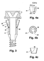
- a hollow truncated cone 31 is provided as a retaining means 30 , which widens in cross-section in the direction of the actuating portion 5.
- the truncated cone 31 has at its lower end a radially inwardly projecting edge 32 which engages in the circumferential annular groove 22.
- the truncated cone 31 is secured against axial displacement. It is also conceivable that, instead of the edge 32, one or more discrete projections projecting radially inwards are provided, which engage in corresponding discrete recesses in the shank 15 or in the sheath 8 or in the annular groove 22.
- Fig. 4a is a side view of the truncated cone 31 is shown.
- the truncated cone 31 has a longitudinal slot 33 in its wall.
- the cross-section of the truncated cone 31 can be reduced if the fastening element is pushed together with the truncated cone 31 through an opening in the outer shell. After the truncated cone 31 is passed through an opening in the outer shell, it expands again to its original size and thus engages behind the outer shell. The closure element is thus securely held on the fastener.
- FIG. 4 b shows a plan view of the truncated cone 31. Good to see the slot 33 and the edge 32.
- the slot 33 also allows the placement of the truncated cone 31 on the shank of the fastener. For this purpose, the slot 33 is widened and the truncated cone 31 is pushed axially onto the fastening element until the edge 32 engages in the annular groove.
- FIG. 4c shows a sectional view according to the line IVc-IVc of FIG. 4a.
- the edge 32 projects radially inwards.
- the shaft member 35 does not extend into the actuator 5.
- the end 36 of the shaft member 35 has a retaining plate 37 , which is the compound of different materials, such as a sheath 8 made of plastic and a shaft member 35 made of metal stabilized.
- the end 36 has an axially parallel knurling or toothing 38 , which serves to better transfer of the torque from the operating portion 5 to the shaft member 35.
- any number of other configurations of the end 36 are conceivable which effect a good anchoring of the shaft element 35 in the casing 8 and are suitable for transmitting a torque.
- the shaft 15 has above the circumferential annular groove 22 a recess 34 and thus a relation to the shaft portion 39 of reduced diameter. As a result, a retaining device can rest against the shaft 15 without enlarging the outer diameter of the fastening element 1 at this point, while the fastening element 1 is passed through an opening in an outer shell.
- a shaft member portion has a projection 40 which tapers towards the free end of the fastener 1 and is formed as a conical ring.
- the projection 40 serves to expand material, for example insulating material, which is arranged under the outer shell to the shaft diameter in the region of the sheathing 8.
- a thread 42 is provided on the casing 8 in the upper section.
- the thread 42 extends to the stop 12.
- a closing element is therefore held on the thread 42 in close proximity to the stop 12.
- the thread 42 is made of the same material as the sheath 8 and can either be molded during the injection molding of the sheath 8 or cut later.
- the thread 42 does not extend all the way to the stop 12, but leaves a portion 43 free. In this area, the closing element comes to rest. By the thread 42 prevents the fastener 1 is released from the outer shell.
- the thread 42 therefore constitutes a retaining means 44 .
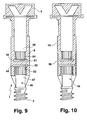
- the fastening element 1 has a shaft element 46 which is interrupted.
- the shaft element 46 therefore comprises the shaft element parts 47 , 48 .
- ends 49, 50 are provided, which have a holding plate 51, 52 and an adjoining knurling or teeth 53, 54 . This measure ensures that the torque introduced at the actuating section 5 is transmitted as far as the free end 3.
- the ends 49, 50 therefore provide anchoring in the casing 8.
- FIG. 10 shows how the region in which the shaft element 46 is interrupted is reinforced by a sleeve 56 .
- the sleeve 56 is arranged in a recess, so that the outer diameter of the shaft 15 is not increased by the sleeve 56.
- a fastening element (1) comprises a metallic shaft element (2) that of a sheath (8) made of a heat-insulating Material is sheathed, and an actuator (5) with a stop (12), at a distance from the Stop (12) on the casing (8) a retainer (9) is provided.
- the retaining device (9) holds an outer shell in the immediate vicinity of the stop (12) on the Shank (15) of the fastener (1).
Landscapes
- Engineering & Computer Science (AREA)
- General Engineering & Computer Science (AREA)
- Mechanical Engineering (AREA)
- Architecture (AREA)
- Civil Engineering (AREA)
- Structural Engineering (AREA)
- Dowels (AREA)
- Roof Covering Using Slabs Or Stiff Sheets (AREA)
- Massaging Devices (AREA)
- Supercharger (AREA)
- Structures Of Non-Positive Displacement Pumps (AREA)
Abstract
Description
- Fig. 1
- Ein Befestigungselement im Längsschnitt, das Finger als Rückhalteeinrichtung aufweist;
- Fig. 2
- das Befestigungselement der Fig. 1, wobei die Finger mit einer Armierung versehen sind;
- Fig. 3
- eine Schnittdarstellung eines Befestigungselements mit einem hohlen Kegelstumpf als Rückhalteeinrichtung;
- Fig. 4a
- eine Seitenansicht eines hohlen Kegelstumpfs;
- Fig. 4b
- eine Draufsicht auf den Kegelstumpf der Fig. 4a;
- Fig. 4c
- eine Schnittdarstellung gemäß der Linie IVc-IVc des Kegelstumpfs der Fig. 4a;
- Fig. 5
- ein Befestigungselement, bei dem sich das Schaftelement nicht bis in den Betätigungsabschnitt erstreckt;
- Fig. 6
- ein Befestigungselement mit einem sich verjüngenden Schaftabschnitt und mit einer Aussparung in der Ummantelung des Schaftelements;
- Fig. 7
- eine erste Darstellung eines Befestigungselements mit Gewinde auf der Ummantelung;
- Fig. 8
- eine Schnittdarstellung des Befestigungselements der Fig. 7;
- Fig. 9
- ein Befestigungselement mit unterbrochenem Schaftelement;
- Fig. 10
- ein Befestigungselement gemäß der Fig. 9 mit Verstärkungshülse.
Claims (17)
- Befestigungselement (1) zum Befestigen einer Außenschale an einem Unterbau, mit einem Schaftelement (2, 35, 46) aus einem ersten Material und einer das Schaftelement (2, 35, 46) zumindest teilweise ummantelnden Ummantelung (8) aus einem wärmeisolierenden Material und mit einem Betätigungsabschnitt (5), an den sich ein Anschlag (12) für die Außenschale anschließt, dadurch gekennzeichnet, dass an der Ummantelung (8) eine Rückhalteeinrichtung (9, 30, 44) vorgesehen ist, die die Außenschale bei montiertem Befestigungselement (1) hintergreift.
- Befestigungselement nach Anspruch 1, dadurch gekennzeichnet, dass die Rückhalteeinrichtung (9, ) reversibel verformbar ist.
- Befestigungselement nach einem der vorhergehenden Ansprüche, dadurch gekennzeichnet, dass die Rückhalteeinrichtung (9, 44) materialschlüssig mit der Ummantelung (8) ausgeführt ist.
- Befestigungselement nach einem der vorhergehenden Ansprüche, dadurch gekennzeichnet, dass die Rückhalteeinrichtung (9) als mindestens ein elastischer Finger (10, 11) ausgebildet ist.
- Befestigungselement nach einem der vorhergehenden Ansprüche, dadurch gekennzeichnet, dass die Rückhalteeinrichtung (9) als über den Umfang der Ummantelung (8) verteilte Finger (10, 11) ausgebildet ist.
- Befestigungselement nach einem der vorhergehenden Ansprüche 4 oder 5, dadurch gekennzeichnet, dass die Finger (10, 11) Verstärkungselemente aufweisen.
- Befestigungselement nach einem der vorhergehenden Ansprüche, dadurch gekennzeichnet, dass die Rückhalteeinrichtung (9) eine Armierung (20, 21) aufweist.
- Befestigungselement nach einem der vorhergehenden Ansprüche, dadurch gekennzeichnet, dass die Rückhalteeinrichtung (30) einen hohlen Kegelstumpf (31) mit einem Längsschlitz (33) umfasst.
- Befestigungselement nach Anspruch 8, dadurch gekennzeichnet, dass der Kegelstumpf (31) an seinem verjüngten Ende mindestens einen radial nach innen vorstehenden Vorsprung, insbesondere einen Rand (32) aufweist, der mit einer entsprechenden an der Ummantelung (8)ausgebildeten Ausnehmung, insbesondere einer Ringnut (22), zusammenwirkt.
- Befestigungselement nach einem der vorhergehenden Ansprüche, dadurch gekennzeichnet, dass an der Ummantelung (8) eine an die Rückhalteeinrichtung (9, 30, 44) angepassten Aussparung (34) vorgesehen ist.
- Befestigungselement nach Anspruch 1, dadurch gekennzeichnet, dass die Ummantelung (8) ein Gewinde (42) aufweist.
- Befestigungselement nach Anspruch 11, dadurch gekennzeichnet, dass das Gewinde (42) an einer auf die Ummantelung (8) aufsteckbaren Gewindehülse ausgebildet ist.
- Befestigungselement nach einem der vorhergehenden Ansprüche, dadurch gekennzeichnet, dass der Betätigungsabschnitt (5) sich materialschlüssig an die Ummantelung (8) anschließt und sich das Schaftelement (2, 46) bis in das Betätigungselement (5) erstreckt.
- Befestigungselement nach einem der vorhergehenden Ansprüche, dadurch gekennzeichnet, dass das Schaftelement (46) unterbrochen ist, wobei über die Ummantelung (8) ein Kraftschluss zwischen den Schaftelementteilen (47, 48) hergestellt ist.
- Befestigungselement nach Anspruch 14, dadurch gekennzeichnet, dass die Ummantelung (8) im Bereich der Unterbrechung des Schaftelements (46) eine Verstärkungshülse (56) aufweist.
- Befestigungselement nach einem der vorhergehenden Ansprüche, dadurch gekennzeichnet, dass das Schaftelement (2, 35, 46) in einem Schaftelementbereich mindestens einen Vorsprung (6, 7, 40) aufweist, der sich in Richtung des freien Endes (3) des Befestigungselements (1) verjüngt.
- Befestigungselement nach Anspruch 16, dadurch gekennzeichnet, dass sich die Ummantelung (8) an den Schaftelementbereich anschließt.
Applications Claiming Priority (2)
| Application Number | Priority Date | Filing Date | Title |
|---|---|---|---|
| DE10361586 | 2003-12-23 | ||
| DE10361586A DE10361586A1 (de) | 2003-12-23 | 2003-12-23 | Befestigungselement |
Publications (3)
| Publication Number | Publication Date |
|---|---|
| EP1548298A2 true EP1548298A2 (de) | 2005-06-29 |
| EP1548298A3 EP1548298A3 (de) | 2006-08-30 |
| EP1548298B1 EP1548298B1 (de) | 2008-07-09 |
Family
ID=34530415
Family Applications (1)
| Application Number | Title | Priority Date | Filing Date |
|---|---|---|---|
| EP04024722A Expired - Lifetime EP1548298B1 (de) | 2003-12-23 | 2004-10-16 | Befestigungselement |
Country Status (3)
| Country | Link |
|---|---|
| EP (1) | EP1548298B1 (de) |
| AT (1) | ATE400744T1 (de) |
| DE (2) | DE10361586A1 (de) |
Cited By (8)
| Publication number | Priority date | Publication date | Assignee | Title |
|---|---|---|---|---|
| DE202005017976U1 (de) * | 2005-11-15 | 2007-03-29 | Dr. Hahn Gmbh & Co. Kg | Montageschraube zur Befestigung von Beschlagteilen, insbesondere von Bandteilen an Hohlkammerprofilen |
| DE102006036979A1 (de) * | 2006-08-08 | 2008-02-21 | Mage Ag | Schraube und Isolationspaneelverkleidung |
| WO2009071168A1 (de) * | 2007-12-06 | 2009-06-11 | Fischerwerke Gmbh & Co. Kg | Dämmstoffhalter und verfahren zum befestigen einer dämmstoffplatte |
| GB2472374A (en) * | 2009-05-18 | 2011-02-09 | Wellmac Ltd | Fastening member |
| CN103486124A (zh) * | 2012-06-08 | 2014-01-01 | 钛积光电(厦门)有限公司 | 卡合至少两组件的固定机构 |
| DE102017217147A1 (de) * | 2017-09-27 | 2019-03-28 | Van Roij Fasteners Europe Bv | Distanzbefestiger |
| CN113968289A (zh) * | 2018-01-10 | 2022-01-25 | 北极星工业有限公司 | 无级变速器 |
| US12391199B2 (en) | 2022-11-11 | 2025-08-19 | Polaris Industries Inc. | Utility vehicle fluid containment system |
Families Citing this family (2)
| Publication number | Priority date | Publication date | Assignee | Title |
|---|---|---|---|---|
| DE102007038976A1 (de) * | 2007-08-17 | 2009-03-12 | Ludwig Hettich & Co. | Schraubanker für Befestigungen in Beton und Mauerwerk |
| DE202008014305U1 (de) * | 2008-10-28 | 2010-04-01 | Sfs Intec Holding Ag | Schraube und damit hergestellte Verbindung |
Family Cites Families (11)
| Publication number | Priority date | Publication date | Assignee | Title |
|---|---|---|---|---|
| NL128090C (de) * | 1964-06-18 | 1900-01-01 | ||
| DE7045239U (de) * | 1970-12-08 | 1973-08-23 | Fischer A | Befestigungselement aus Kunststoff fur dünne Platten, Hohlwande oder dgl |
| DE3140861A1 (de) * | 1981-10-14 | 1983-04-21 | Hilti AG, 9494 Schaan | Verfahren, stuetzkoerper und duebel zur abstandsbefestigung von fassadenplatten bzw. fassadentraegern |
| DE3400474A1 (de) * | 1984-01-09 | 1985-07-18 | Hilti Ag, Schaan | Spreizduebel |
| DE3436466A1 (de) * | 1984-10-05 | 1986-04-10 | EJOT Baubefestigungen GmbH, 5928 Bad Laasphe | Schraube |
| US4726722A (en) * | 1987-02-24 | 1988-02-23 | Phillips Plastics Corporation | Fastener for spaced-apart panels |
| FR2640330B1 (fr) * | 1988-12-08 | 1991-04-05 | Peugeot | Dispositif de fixation a un element de structure interne d'un vehicule automobile d'une piece d'equipement a positionner relativement a un element de structure externe du vehicule |
| DE8903833U1 (de) * | 1989-03-29 | 1989-05-18 | Biermeier, Adolf | Distanzschraube |
| US6394724B1 (en) * | 2000-01-21 | 2002-05-28 | Pem Management, Inc. | Snap-in panel fastener |
| DE10147831B4 (de) * | 2001-02-21 | 2006-11-02 | Deutsche Rockwool Mineralwoll Gmbh + Co Ohg | Ständerwand |
| DE20203278U1 (de) * | 2002-02-28 | 2002-05-23 | Mage Ag, Courtaman | Befestigungselement |
-
2003
- 2003-12-23 DE DE10361586A patent/DE10361586A1/de not_active Ceased
-
2004
- 2004-10-16 AT AT04024722T patent/ATE400744T1/de not_active IP Right Cessation
- 2004-10-16 EP EP04024722A patent/EP1548298B1/de not_active Expired - Lifetime
- 2004-10-16 DE DE502004007545T patent/DE502004007545D1/de not_active Expired - Lifetime
Cited By (11)
| Publication number | Priority date | Publication date | Assignee | Title |
|---|---|---|---|---|
| DE202005017976U1 (de) * | 2005-11-15 | 2007-03-29 | Dr. Hahn Gmbh & Co. Kg | Montageschraube zur Befestigung von Beschlagteilen, insbesondere von Bandteilen an Hohlkammerprofilen |
| DE102006036979A1 (de) * | 2006-08-08 | 2008-02-21 | Mage Ag | Schraube und Isolationspaneelverkleidung |
| DE102006036979B4 (de) * | 2006-08-08 | 2008-08-28 | Mage Ag | Schraube und Isolationspaneelverkleidung |
| WO2009071168A1 (de) * | 2007-12-06 | 2009-06-11 | Fischerwerke Gmbh & Co. Kg | Dämmstoffhalter und verfahren zum befestigen einer dämmstoffplatte |
| GB2472374A (en) * | 2009-05-18 | 2011-02-09 | Wellmac Ltd | Fastening member |
| GB2472374B (en) * | 2009-05-18 | 2013-06-12 | Wellmac Ltd | Fastening member |
| CN103486124A (zh) * | 2012-06-08 | 2014-01-01 | 钛积光电(厦门)有限公司 | 卡合至少两组件的固定机构 |
| DE102017217147A1 (de) * | 2017-09-27 | 2019-03-28 | Van Roij Fasteners Europe Bv | Distanzbefestiger |
| CN113968289A (zh) * | 2018-01-10 | 2022-01-25 | 北极星工业有限公司 | 无级变速器 |
| US12258077B2 (en) | 2018-01-10 | 2025-03-25 | Polaris Industries Inc. | Vehicle |
| US12391199B2 (en) | 2022-11-11 | 2025-08-19 | Polaris Industries Inc. | Utility vehicle fluid containment system |
Also Published As
| Publication number | Publication date |
|---|---|
| DE502004007545D1 (de) | 2008-08-21 |
| EP1548298B1 (de) | 2008-07-09 |
| DE10361586A1 (de) | 2005-07-21 |
| ATE400744T1 (de) | 2008-07-15 |
| EP1548298A3 (de) | 2006-08-30 |
Similar Documents
| Publication | Publication Date | Title |
|---|---|---|
| DE2906812C2 (de) | ||
| EP2906475B1 (de) | Verschlusskappe, behälterhals, garantieverschluss sowie verfahren zur herstellung eines garantieverschlusses | |
| EP1719450A1 (de) | Vorrichtung zum Einbringen eines Ankerelements samt Faden in einen Knochen | |
| DE102010060771A1 (de) | Befestigungselement | |
| EP3565976B1 (de) | Vorrichtung zur drehmomentbegrenzung mit drei stegen | |
| DE2913090A1 (de) | Befestigungselement mit ankerbolzen und spreizkeil | |
| EP1548298B1 (de) | Befestigungselement | |
| DE4414765A1 (de) | Schraubbefestigung | |
| DE3639870A1 (de) | Sicherungseinrichtung zum nachweis des unbefugten oeffnens eines gehaeuses | |
| DE102024112582A1 (de) | Trockenbaudübel und Verfahren zur Montage des Trockenbaudübels | |
| EP3147079A1 (de) | Vorrichtung zur drehmomentbegrenzung | |
| EP3565977B1 (de) | Bruchmutter mit bruchfläche mit grossem öffnungswinkel | |
| DE102012008521B4 (de) | Ölwannenanordnung | |
| EP3500768B1 (de) | Drehmomentbegrenzer | |
| DE2605310A1 (de) | Bolzenelement zur befestigung in einer sockelbohrung | |
| DE69934409T2 (de) | Werkzeug und verfahren zum abscheren von bolzen | |
| DE19960198A1 (de) | Mittel zum Festlegen eines Gegenstandes, insbesondere Klemmschraube, Distanzierelement für ein solches Mittel und Schraubverbindungsklemme mit einem solchen Mittel | |
| WO2003085274A1 (de) | Vorrichtung zum verspannenden verbinden von mit abstand zueinander liegenden bauteilen | |
| CH689289A5 (de) | Hohlkoerper zur Installation von elektrischen Einrichtungen in Betonbauten. | |
| EP3567264B1 (de) | Befestigungssystem | |
| CH707700A1 (de) | Installationsvorrichtung. | |
| WO2025051555A1 (de) | Trockenbaudübel und verfahren zur montage des trockenbaudübels | |
| EP2148099B1 (de) | Verankerungselement | |
| DE4024963A1 (de) | Duebel mit einer duebelhuelse | |
| DE3424075C2 (de) | Steckverbinder |
Legal Events
| Date | Code | Title | Description |
|---|---|---|---|
| PUAI | Public reference made under article 153(3) epc to a published international application that has entered the european phase |
Free format text: ORIGINAL CODE: 0009012 |
|
| AK | Designated contracting states |
Kind code of ref document: A2 Designated state(s): AT BE BG CH CY CZ DE DK EE ES FI FR GB GR HU IE IT LI LU MC NL PL PT RO SE SI SK TR |
|
| AX | Request for extension of the european patent |
Extension state: AL HR LT LV MK |
|
| PUAL | Search report despatched |
Free format text: ORIGINAL CODE: 0009013 |
|
| AK | Designated contracting states |
Kind code of ref document: A3 Designated state(s): AT BE BG CH CY CZ DE DK EE ES FI FR GB GR HU IE IT LI LU MC NL PL PT RO SE SI SK TR |
|
| AX | Request for extension of the european patent |
Extension state: AL HR LT LV MK |
|
| RIC1 | Information provided on ipc code assigned before grant |
Ipc: F16B 35/06 20060101AFI20050401BHEP Ipc: F16B 41/00 20060101ALI20060725BHEP Ipc: F16B 37/14 20060101ALI20060725BHEP |
|
| 17P | Request for examination filed |
Effective date: 20070224 |
|
| AKX | Designation fees paid |
Designated state(s): AT BE BG CH CY CZ DE DK EE ES FI FR GB GR HU IE IT LI LU MC NL PL PT RO SE SI SK TR |
|
| 17Q | First examination report despatched |
Effective date: 20070425 |
|
| GRAP | Despatch of communication of intention to grant a patent |
Free format text: ORIGINAL CODE: EPIDOSNIGR1 |
|
| GRAS | Grant fee paid |
Free format text: ORIGINAL CODE: EPIDOSNIGR3 |
|
| GRAA | (expected) grant |
Free format text: ORIGINAL CODE: 0009210 |
|
| AK | Designated contracting states |
Kind code of ref document: B1 Designated state(s): AT BE BG CH CY CZ DE DK EE ES FI FR GB GR HU IE IT LI LU MC NL PL PT RO SE SI SK TR |
|
| REG | Reference to a national code |
Ref country code: GB Ref legal event code: FG4D Free format text: NOT ENGLISH |
|
| REG | Reference to a national code |
Ref country code: CH Ref legal event code: EP |
|
| REF | Corresponds to: |
Ref document number: 502004007545 Country of ref document: DE Date of ref document: 20080821 Kind code of ref document: P |
|
| REG | Reference to a national code |
Ref country code: IE Ref legal event code: FG4D Free format text: LANGUAGE OF EP DOCUMENT: GERMAN |
|
| REG | Reference to a national code |
Ref country code: SE Ref legal event code: TRGR |
|
| PG25 | Lapsed in a contracting state [announced via postgrant information from national office to epo] |
Ref country code: PT Free format text: LAPSE BECAUSE OF FAILURE TO SUBMIT A TRANSLATION OF THE DESCRIPTION OR TO PAY THE FEE WITHIN THE PRESCRIBED TIME-LIMIT Effective date: 20081209 Ref country code: ES Free format text: LAPSE BECAUSE OF FAILURE TO SUBMIT A TRANSLATION OF THE DESCRIPTION OR TO PAY THE FEE WITHIN THE PRESCRIBED TIME-LIMIT Effective date: 20081020 |
|
| PGFP | Annual fee paid to national office [announced via postgrant information from national office to epo] |
Ref country code: CH Payment date: 20081003 Year of fee payment: 5 |
|
| PG25 | Lapsed in a contracting state [announced via postgrant information from national office to epo] |
Ref country code: FI Free format text: LAPSE BECAUSE OF FAILURE TO SUBMIT A TRANSLATION OF THE DESCRIPTION OR TO PAY THE FEE WITHIN THE PRESCRIBED TIME-LIMIT Effective date: 20080709 Ref country code: BG Free format text: LAPSE BECAUSE OF FAILURE TO SUBMIT A TRANSLATION OF THE DESCRIPTION OR TO PAY THE FEE WITHIN THE PRESCRIBED TIME-LIMIT Effective date: 20081009 Ref country code: SI Free format text: LAPSE BECAUSE OF FAILURE TO SUBMIT A TRANSLATION OF THE DESCRIPTION OR TO PAY THE FEE WITHIN THE PRESCRIBED TIME-LIMIT Effective date: 20080709 |
|
| REG | Reference to a national code |
Ref country code: IE Ref legal event code: FD4D |
|
| PG25 | Lapsed in a contracting state [announced via postgrant information from national office to epo] |
Ref country code: DK Free format text: LAPSE BECAUSE OF FAILURE TO SUBMIT A TRANSLATION OF THE DESCRIPTION OR TO PAY THE FEE WITHIN THE PRESCRIBED TIME-LIMIT Effective date: 20080709 Ref country code: EE Free format text: LAPSE BECAUSE OF FAILURE TO SUBMIT A TRANSLATION OF THE DESCRIPTION OR TO PAY THE FEE WITHIN THE PRESCRIBED TIME-LIMIT Effective date: 20080709 Ref country code: IE Free format text: LAPSE BECAUSE OF FAILURE TO SUBMIT A TRANSLATION OF THE DESCRIPTION OR TO PAY THE FEE WITHIN THE PRESCRIBED TIME-LIMIT Effective date: 20080709 |
|
| PLBE | No opposition filed within time limit |
Free format text: ORIGINAL CODE: 0009261 |
|
| STAA | Information on the status of an ep patent application or granted ep patent |
Free format text: STATUS: NO OPPOSITION FILED WITHIN TIME LIMIT |
|
| PG25 | Lapsed in a contracting state [announced via postgrant information from national office to epo] |
Ref country code: SK Free format text: LAPSE BECAUSE OF FAILURE TO SUBMIT A TRANSLATION OF THE DESCRIPTION OR TO PAY THE FEE WITHIN THE PRESCRIBED TIME-LIMIT Effective date: 20080709 Ref country code: MC Free format text: LAPSE BECAUSE OF NON-PAYMENT OF DUE FEES Effective date: 20081031 Ref country code: CZ Free format text: LAPSE BECAUSE OF FAILURE TO SUBMIT A TRANSLATION OF THE DESCRIPTION OR TO PAY THE FEE WITHIN THE PRESCRIBED TIME-LIMIT Effective date: 20080709 Ref country code: RO Free format text: LAPSE BECAUSE OF FAILURE TO SUBMIT A TRANSLATION OF THE DESCRIPTION OR TO PAY THE FEE WITHIN THE PRESCRIBED TIME-LIMIT Effective date: 20080709 |
|
| 26N | No opposition filed |
Effective date: 20090414 |
|
| GBPC | Gb: european patent ceased through non-payment of renewal fee |
Effective date: 20081016 |
|
| REG | Reference to a national code |
Ref country code: FR Ref legal event code: ST Effective date: 20090630 |
|
| PG25 | Lapsed in a contracting state [announced via postgrant information from national office to epo] |
Ref country code: IT Free format text: LAPSE BECAUSE OF FAILURE TO SUBMIT A TRANSLATION OF THE DESCRIPTION OR TO PAY THE FEE WITHIN THE PRESCRIBED TIME-LIMIT Effective date: 20080709 |
|
| PG25 | Lapsed in a contracting state [announced via postgrant information from national office to epo] |
Ref country code: FR Free format text: LAPSE BECAUSE OF NON-PAYMENT OF DUE FEES Effective date: 20081031 |
|
| PG25 | Lapsed in a contracting state [announced via postgrant information from national office to epo] |
Ref country code: GB Free format text: LAPSE BECAUSE OF NON-PAYMENT OF DUE FEES Effective date: 20081016 |
|
| PG25 | Lapsed in a contracting state [announced via postgrant information from national office to epo] |
Ref country code: AT Free format text: LAPSE BECAUSE OF NON-PAYMENT OF DUE FEES Effective date: 20081016 |
|
| PG25 | Lapsed in a contracting state [announced via postgrant information from national office to epo] |
Ref country code: PL Free format text: LAPSE BECAUSE OF FAILURE TO SUBMIT A TRANSLATION OF THE DESCRIPTION OR TO PAY THE FEE WITHIN THE PRESCRIBED TIME-LIMIT Effective date: 20080709 |
|
| REG | Reference to a national code |
Ref country code: CH Ref legal event code: PL |
|
| PG25 | Lapsed in a contracting state [announced via postgrant information from national office to epo] |
Ref country code: LU Free format text: LAPSE BECAUSE OF NON-PAYMENT OF DUE FEES Effective date: 20081016 Ref country code: CY Free format text: LAPSE BECAUSE OF FAILURE TO SUBMIT A TRANSLATION OF THE DESCRIPTION OR TO PAY THE FEE WITHIN THE PRESCRIBED TIME-LIMIT Effective date: 20080709 Ref country code: HU Free format text: LAPSE BECAUSE OF FAILURE TO SUBMIT A TRANSLATION OF THE DESCRIPTION OR TO PAY THE FEE WITHIN THE PRESCRIBED TIME-LIMIT Effective date: 20090110 |
|
| PG25 | Lapsed in a contracting state [announced via postgrant information from national office to epo] |
Ref country code: TR Free format text: LAPSE BECAUSE OF FAILURE TO SUBMIT A TRANSLATION OF THE DESCRIPTION OR TO PAY THE FEE WITHIN THE PRESCRIBED TIME-LIMIT Effective date: 20080709 |
|
| PG25 | Lapsed in a contracting state [announced via postgrant information from national office to epo] |
Ref country code: LI Free format text: LAPSE BECAUSE OF NON-PAYMENT OF DUE FEES Effective date: 20091031 Ref country code: CH Free format text: LAPSE BECAUSE OF NON-PAYMENT OF DUE FEES Effective date: 20091031 Ref country code: GR Free format text: LAPSE BECAUSE OF FAILURE TO SUBMIT A TRANSLATION OF THE DESCRIPTION OR TO PAY THE FEE WITHIN THE PRESCRIBED TIME-LIMIT Effective date: 20081010 |
|
| PGFP | Annual fee paid to national office [announced via postgrant information from national office to epo] |
Ref country code: SE Payment date: 20121023 Year of fee payment: 9 |
|
| REG | Reference to a national code |
Ref country code: SE Ref legal event code: EUG |
|
| PG25 | Lapsed in a contracting state [announced via postgrant information from national office to epo] |
Ref country code: SE Free format text: LAPSE BECAUSE OF NON-PAYMENT OF DUE FEES Effective date: 20131017 |
|
| PGFP | Annual fee paid to national office [announced via postgrant information from national office to epo] |
Ref country code: DE Payment date: 20151126 Year of fee payment: 12 |
|
| PGFP | Annual fee paid to national office [announced via postgrant information from national office to epo] |
Ref country code: NL Payment date: 20151124 Year of fee payment: 12 Ref country code: BE Payment date: 20151124 Year of fee payment: 12 |
|
| PG25 | Lapsed in a contracting state [announced via postgrant information from national office to epo] |
Ref country code: BE Free format text: LAPSE BECAUSE OF NON-PAYMENT OF DUE FEES Effective date: 20161031 |
|
| REG | Reference to a national code |
Ref country code: DE Ref legal event code: R119 Ref document number: 502004007545 Country of ref document: DE |
|
| REG | Reference to a national code |
Ref country code: NL Ref legal event code: MM Effective date: 20161101 |
|
| PG25 | Lapsed in a contracting state [announced via postgrant information from national office to epo] |
Ref country code: DE Free format text: LAPSE BECAUSE OF NON-PAYMENT OF DUE FEES Effective date: 20170503 |
|
| PG25 | Lapsed in a contracting state [announced via postgrant information from national office to epo] |
Ref country code: NL Free format text: LAPSE BECAUSE OF NON-PAYMENT OF DUE FEES Effective date: 20161101 |
|
| REG | Reference to a national code |
Ref country code: BE Ref legal event code: MM Effective date: 20161031 |