EP1548340A1 - Armatur mit Positionsanzeigevorrichtung - Google Patents
Armatur mit Positionsanzeigevorrichtung Download PDFInfo
- Publication number
- EP1548340A1 EP1548340A1 EP20030079185 EP03079185A EP1548340A1 EP 1548340 A1 EP1548340 A1 EP 1548340A1 EP 20030079185 EP20030079185 EP 20030079185 EP 03079185 A EP03079185 A EP 03079185A EP 1548340 A1 EP1548340 A1 EP 1548340A1
- Authority
- EP
- European Patent Office
- Prior art keywords
- valve
- skirt
- annular support
- support piece
- steering wheel
- Prior art date
- Legal status (The legal status is an assumption and is not a legal conclusion. Google has not performed a legal analysis and makes no representation as to the accuracy of the status listed.)
- Granted
Links
- 230000011664 signaling Effects 0.000 claims description 25
- 230000033001 locomotion Effects 0.000 claims description 19
- 238000006073 displacement reaction Methods 0.000 claims description 7
- 239000000463 material Substances 0.000 claims description 7
- 230000000694 effects Effects 0.000 claims description 4
- 230000008878 coupling Effects 0.000 claims description 3
- 238000010168 coupling process Methods 0.000 claims description 3
- 238000005859 coupling reaction Methods 0.000 claims description 3
- 229920003023 plastic Polymers 0.000 claims description 3
- 239000004033 plastic Substances 0.000 claims description 3
- 210000004907 gland Anatomy 0.000 claims description 2
- 230000000630 rising effect Effects 0.000 description 2
- 238000004519 manufacturing process Methods 0.000 description 1
- 238000012856 packing Methods 0.000 description 1
- 230000002093 peripheral effect Effects 0.000 description 1
- 230000000452 restraining effect Effects 0.000 description 1
- 238000007789 sealing Methods 0.000 description 1
Images



Classifications
-
- F—MECHANICAL ENGINEERING; LIGHTING; HEATING; WEAPONS; BLASTING
- F17—STORING OR DISTRIBUTING GASES OR LIQUIDS
- F17C—VESSELS FOR CONTAINING OR STORING COMPRESSED, LIQUEFIED OR SOLIDIFIED GASES; FIXED-CAPACITY GAS-HOLDERS; FILLING VESSELS WITH, OR DISCHARGING FROM VESSELS, COMPRESSED, LIQUEFIED, OR SOLIDIFIED GASES
- F17C13/00—Details of vessels or of the filling or discharging of vessels
- F17C13/06—Closures, e.g. cap, breakable member
-
- F—MECHANICAL ENGINEERING; LIGHTING; HEATING; WEAPONS; BLASTING
- F16—ENGINEERING ELEMENTS AND UNITS; GENERAL MEASURES FOR PRODUCING AND MAINTAINING EFFECTIVE FUNCTIONING OF MACHINES OR INSTALLATIONS; THERMAL INSULATION IN GENERAL
- F16K—VALVES; TAPS; COCKS; ACTUATING-FLOATS; DEVICES FOR VENTING OR AERATING
- F16K1/00—Lift valves or globe valves, i.e. cut-off apparatus with closure members having at least a component of their opening and closing motion perpendicular to the closing faces
- F16K1/30—Lift valves or globe valves, i.e. cut-off apparatus with closure members having at least a component of their opening and closing motion perpendicular to the closing faces specially adapted for pressure containers
- F16K1/301—Lift valves or globe valves, i.e. cut-off apparatus with closure members having at least a component of their opening and closing motion perpendicular to the closing faces specially adapted for pressure containers only shut-off valves, i.e. valves without additional means
- F16K1/302—Lift valves or globe valves, i.e. cut-off apparatus with closure members having at least a component of their opening and closing motion perpendicular to the closing faces specially adapted for pressure containers only shut-off valves, i.e. valves without additional means with valve member and actuator on the same side of the seat
-
- F—MECHANICAL ENGINEERING; LIGHTING; HEATING; WEAPONS; BLASTING
- F16—ENGINEERING ELEMENTS AND UNITS; GENERAL MEASURES FOR PRODUCING AND MAINTAINING EFFECTIVE FUNCTIONING OF MACHINES OR INSTALLATIONS; THERMAL INSULATION IN GENERAL
- F16K—VALVES; TAPS; COCKS; ACTUATING-FLOATS; DEVICES FOR VENTING OR AERATING
- F16K37/00—Special means in or on valves or other cut-off apparatus for indicating or recording operation thereof, or for enabling an alarm to be given
- F16K37/0008—Mechanical means
-
- F—MECHANICAL ENGINEERING; LIGHTING; HEATING; WEAPONS; BLASTING
- F17—STORING OR DISTRIBUTING GASES OR LIQUIDS
- F17C—VESSELS FOR CONTAINING OR STORING COMPRESSED, LIQUEFIED OR SOLIDIFIED GASES; FIXED-CAPACITY GAS-HOLDERS; FILLING VESSELS WITH, OR DISCHARGING FROM VESSELS, COMPRESSED, LIQUEFIED, OR SOLIDIFIED GASES
- F17C13/00—Details of vessels or of the filling or discharging of vessels
- F17C13/02—Special adaptations of indicating, measuring, or monitoring equipment
-
- F—MECHANICAL ENGINEERING; LIGHTING; HEATING; WEAPONS; BLASTING
- F17—STORING OR DISTRIBUTING GASES OR LIQUIDS
- F17C—VESSELS FOR CONTAINING OR STORING COMPRESSED, LIQUEFIED OR SOLIDIFIED GASES; FIXED-CAPACITY GAS-HOLDERS; FILLING VESSELS WITH, OR DISCHARGING FROM VESSELS, COMPRESSED, LIQUEFIED, OR SOLIDIFIED GASES
- F17C13/00—Details of vessels or of the filling or discharging of vessels
- F17C13/04—Arrangement or mounting of valves
-
- Y—GENERAL TAGGING OF NEW TECHNOLOGICAL DEVELOPMENTS; GENERAL TAGGING OF CROSS-SECTIONAL TECHNOLOGIES SPANNING OVER SEVERAL SECTIONS OF THE IPC; TECHNICAL SUBJECTS COVERED BY FORMER USPC CROSS-REFERENCE ART COLLECTIONS [XRACs] AND DIGESTS
- Y10—TECHNICAL SUBJECTS COVERED BY FORMER USPC
- Y10T—TECHNICAL SUBJECTS COVERED BY FORMER US CLASSIFICATION
- Y10T137/00—Fluid handling
- Y10T137/8158—With indicator, register, recorder, alarm or inspection means
- Y10T137/8225—Position or extent of motion indicator
Definitions
- the invention relates to a tap, in particular a tap for a bottle of gas or liquefied gas, having a valve body forming part of a structure fixed valve, a rotary wheel relative to the structure tap and around an axis of rotation to open or close the tap, and a way to indicate the position open or closed tap, this means comprising an element mobile to hide or expose a signaling medium so to indicate by the visibility or the invisibility of this means of signaling the state of opening or closing of the valve.
- Faucets with means or device allowing to see the closed or open state of the tap at outside of it are known in the art earlier.
- a ring fixed is mounted on the valve body. This ring is normally hidden by the steering wheel of the faucet and she has a other color than the faucet body and the steering wheel.
- This simple system works only with a stem tap up and down because the aforementioned ring can be discovered or made visible only by the wheel of the tap if it moves away from the faucet body when opening tap.
- the distance of the steering wheel is limited and the ring indicating the open position of the faucet is barely or difficult to see.
- faucets are known having other rather complex and bulky devices to indicate the open or closed condition of the faucet.
- the present invention aims to remedy these disadvantages and provide a faucet with a simple way or device to indicate the open or closed condition of the tap, which is clearly visible outside the faucet, and who is getting ready for a rising and falling stem cock, a rotating stem valve (without raising and lowering) and also for a tap to open by a fraction of a turn of revolution or several revolutions of the steering wheel.
- the tap of the aforementioned type is characterized in that the movable member of the faucet is a skirt coupled, on one side, driving to be driven in rotation by it and to be able to move axially in relation to it and, coupled, on the other side, to a element of the fixed structure of the faucet by means causing, under the effect of the rotational movement of the skirt in one or the other direction, an axial displacement of the latter along the axis of rotation with respect to the steering wheel and the structure fixed valve to conceal or expose the means of signaling.
- the moving skirt of the means for indicating the position open or closed tap performs an upward movement or descending in response to the steering wheel rotation movement tap to discover or cover the means of signaling even if the steering wheel or the valve stem go up and do not go down.
- the coupling between the mobile skirt and the fixed element of the faucet can be designed by selecting a appropriate angle of inclination or helix of the means commitment between these two parts to produce a sufficient axial movement of the moving skirt to discover or expose a large signaling area at height or substantial width to be easily visible to the outside of the faucet.
- a large signaling area at height Substantial can also be exposed.
- the device or means for indicating the state of opening or valve closure includes a support piece ring separate from the faucet body and mounted normally motionless relative to it, and the moving skirt surrounds the annular support piece and is provided with a thread internal to one or more threads engaged with a part corresponding external thread of the support piece.
- the signaling means is provided on the annular support piece and this signaling means is found on a lower part of the support piece made visible by the axial movement of the skirt when the Faucet is turned. At least the lower part of the annular support piece provided with the signaling (or as a means of signaling) or the whole of this piece can be distinguished from the surfaces neighboring faucet by at least one of the conditions having a different surface finish, a color different and different material.
- the annular support piece is secured to the body of the valve by friction by means of a pressing commitment and it is further provided with a central shape opening polygonal or star, for example at 24 angles or facets arranged in zigzag or accordion, engaged on a end of polygonal shape, for example square or hexagonal, of a packing ring.
- the support piece annular further comprises one or more primers of rupture to open or close the tap in case of locking of the skirt on the annular support piece, by the application of sufficient steering force causing the rupture of the rupture primers.
- the scale of the pressed engagement of the annular support piece on the faucet body and the polygonal shape of the opening of this support piece are chosen so that the piece of support can be rotated relative to the valve body and the stuffing ring if the support piece is made of a tenacious material preventing the breaking of the primers of break.
- the mobile skirt To couple the mobile skirt to the steering wheel to be turned with this one it is provided at its end top of a rim provided with several projecting parts spaced from each other in the circumferential direction and received in correspondingly shaped valleys inside a steering wheel cavity.
- the lower end of the skirt is visible at the bottom of the steering wheel at least in its position hiding the indication means.
- the mobile skirt occupies a lower position hiding the lower end of the annular support piece or the means of signaling provided for at or near his bottom end and by the rotational movement of the flying in tap opening direction the moving skirt is caused to move axially upwards in order to discover the lower end part of the piece of annular support or its means of signaling the tap position to be easily visible even at distance, outside the tap to signal the open position of the tap.
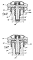
- valve 10 comprises a valve body 12, a steering wheel 14 coupled to a rod 16 which in turn is coupled to a seat mobile 18 bearing a sealing ring 20 engaging a fixed seat 22 of the valve body in the closed position of tap.
- the rod 16 is housed for rotation in a ring 24 screwed in a threaded part at the end upper body of the valve 12.
- the rod 16 is provided with its lower end of a square part 26 engaged in a square-shaped cavity 28 of the mobile seat 18.
- the seat mobile 18 is screwed into a threaded portion within the valve body 12.
- the valve 10 is therefore a type of rotating stem valve, that is, the stem does not move not vertically or axially to open or close tap. Only the moving seat 18 moves vertically or axially when the rod 16 is rotated in the opening or closing direction of the valve.
- the mechanism indicating the open or closed position of the valve 10, designated as a whole by 30 has a movable skirt cylindrical outer member 32 and an annular support member internal cylindrical 34.
- the movable skirt 32 is coupled to the flying 14 to be rotated by the steering wheel 14 while permitting axial movement of the skirt 32 the along the longitudinal axis A of the valve 10 relative to the annular support piece 34 and the steering wheel 14 and also by relative to the valve body 12.
- the skirt 32 surrounds the piece of annular support 34 and the upper part of the skirt 32 is received inside the steering wheel 14 while its part lower is visible and is outside the steering wheel at the bottom of it.
- the support piece 34 is mounted immobile by friction by a commitment pressed on the body of faucet 12 so that she can not move or turn relative to it in normal operation of the tap.
- the annular support piece 34 is also extended downward beyond the lower end of the steering wheel 14.
- the skirt 32 is provided with an internal thread 36, see FIG. 3A, and this thread 36 is in engagement with a part external thread 38 of the internal support piece 34, see Figure 5A.
- the skirt mobile 32 is provided at one of its ends with a flange 40 provided with several projecting parts, or lobes, 42 of generally semi-circular shape extending towards outside and spaced from each other in the direction circumferential skirt 32. These projections 42 are received in hollows, for example 44, of shape corresponding, see Figure 1, practiced in the surface internal peripheral of a cavity open down formed in the steering wheel 14.
- the skirt 32 is thus coupled to the steering wheel 14 for rotation with this one but can not move in rotational direction relative to the steering wheel 14.
- the projections 42 of the skirt 32 move vertically in the troughs 44 of the steering wheel 14.
- Any other means may be provided for coupling the movable skirt 32 to steering wheel 14, for example, axial studs (not shown) attached to the flywheel 14 and received in axial holes (not shown) practiced in the mobile skirt 32.
- Figures 5A and 5B show the support piece inner ring 34 which is normally stationary or fixed by to the valve body 12.
- the annular support piece 34 is provided at its upper end with a radial wall annular 44 provided in its center with a polygonal opening 46, preferably a star opening with 24 facets arranged in zigzag or accordion, or at 24 angles opening alternately inwards and outwards.
- a polygonal opening 46 preferably a star opening with 24 facets arranged in zigzag or accordion, or at 24 angles opening alternately inwards and outwards.
- the radial annular wall 44 is provided with several elongated curved holes 48 spaced in the direction circumferentially of each other leaving primer rupture 50 between the adjacent holes.
- the support element ring 34 is provided at the bottom of its cylindrical surface internal of several vertical ribs 52 which engage the outer surface of the valve body 12 friction when the annular support piece 34 is pressed on the body of valve 12. If the annular support piece 34 is mounted on the valve body 12, the polygonal opening 46 is received around the polygonal end, square or hexagonal, of the gland ring 24, as shown in FIG.
- Figures 3A, 3B and 3C show the elements rings or rings 32, 34 internally and externally (i.e. the skirt 32 and the support piece 34) assembled from the device indication.
- the skirt 32 hides or covers the lower end of the room support 34.
- the tap is in the closed position.
- FIGS. 3B and 3C the moving skirt 32 is moved up and the part lower 34a of the inner support piece 34 is visible at the bottom of the lower end of the outer skirt 32.
- This position is also shown in Figure 1 and shows the open condition of the valve 10.
- the lower portion 34A of the support piece 34 thus serves as a signaling surface or part of indicating the position of the valve and indicates the open position of the faucet when it is visible below the mobile skirt 32.
- the two elements 32 and 34 are made of plastic and at least the lower part of the support piece 34 has a other color than the mobile skirt 32, for example a color red. It is also possible to manufacture both elements 32 and 34 of different materials and / or to provide for example a glossy appearance or other surface finish for the lower end 34a of the support piece 34, in particularly if the two elements 32 and 34 are metallic.
- the mobile skirt 32 also rotates with the steering wheel 14 and because of the threaded engagement between elements 32 and 34, the element outer or the skirt 32 moves vertically while the inner element 34 remains stationary.
- the helix angle of the thread between the two elements 32 and 34 is chosen enough elevated so as to discover a substantial part of the support piece 34 at its lower end 34a. A axial movement of the steering wheel 14 is not necessary for expose the lower portion 34a of the support piece 34. If the axial displacement of the steering wheel is weak or if its rotation is only a fraction of a turn of revolution, the helix angle of the threaded parts 36 and 38 is chosen high enough to ensure the exposure of a party substantial at the lower end of the support piece 34. It is also possible to provide threads with steps or turns multiple.
- the indication device according to the invention can also be used in combination with an up and down stem valve, that is to say a faucet provided with a steering wheel which moves axially relative to the valve body when the steering wheel is turned for open or close the tap.
- a faucet is shown schematically in FIGS. 2A and 2B, FIG. 2A showing the open position and figure 2B the position closed tap.
- the indication device 30 comprising the skirt 32 and the annular support piece 34 is the same as in the embodiment of FIGS. 1, 3A, 3B, 3C, 4A, 4B and 5A, 5B and need not be described here in detail.
- the valve can be opened or closed by applying a higher rotational force to the steering wheel 14 causing breakage of the breakers 50 of the piece ring support 34.
- the support piece 34 is made of stubborn material preventing the breaking of breaking primers 50 the higher force applied to the 14 flywheel may cause rotation of the support piece 34 around the valve body 12 and around the end polygonal of the tow 34 by deformation of the opening polygonal 46 of the annular support piece 34. heard this force must also overcome the restraining force friction mounting of the annular support member 34 12.
- the friction fitting is therefore a relatively low pressed commitment that is enough for holding the annular support piece 34 against rotation in normal operation in combination with the commitment of the polygonal opening 46 on the polygonal end of the tow 24.
- threaded portions 36 and 38 external and internal elements 32 and 34 it is also possible to foresee any other means causing a vertical or axial movement of the outer member 32 by relative to the inner member 34 when the outer member 32 is turned around the axis A of the tap 10.
- the outer part 32 could have studs (not shown) spaced circumferentially, and extending into the interior of the internal cylindrical surface of the skirt 32 and received in helical grooves (not shown) of the inner element 34.
- the studs may also be provided on the internal support 34 and engage in grooves helical of the skirt 32.
- the inner member or the support member 34 can be removed and the 32 mobile skirt can be mounted directly on the valve body 12 and coupled thereto by any means, for example a threaded engagement, to cause a vertical or axial displacement of the skirt 32 when it is turned by means of the steering wheel 14 around the axis A tap 10.
- a part of the tap body 10 to be discovered or hidden by the skirt 32 serves as a means or signaling surface or indication of the position of the valve 10.
- This part of the valve body 12 can be colored, for example in red color, or may have a other surface finish, for example a glossy appearance, to distinguish it from the surrounding surfaces of the body of the tap 12 and the skirt 32, or could be formed by a colored tape, or other means, applied to the outer surface of the valve body 12.
- the device for indicating the position of the tap 10 can be trained to hide the indication part of the body from valve 12 or element 34 in the closed position of the tap and to expose it in the open position of the tap, as described above, or else, that is to say, for the hide in the open position and expose it to the closed position.
- the mechanism according to the invention allows to see the condition open or closed tap 10 on the outside of it even if the rod 16 and the steering wheel 14 that does not move vertically or axially along the A axis for the opening or closing of the tap 10.
- the same operation is also ensured for a faucet where the rod itself is screwed into the tow or body of the faucet and door seal ring coming to contact the headquarters of tap ( Figures 2A and 2B).
- the signaling portion or surface 34a of the inner element 34 does not need to extend to the lower end of element 34 but the element internal 34 may be provided at its lower end with a small external circumferential stop (not shown) on which the outer portion 32 comes to rest in position closed or open tap, to conceal the part or signaling surface 34a lying above this circumferential stop.
- the outer element 32 can have one or more windows (not shown) discarded circumferentially and / or axially from each other and can be aligned with one or more surfaces of signaling (not shown) arranged in a corresponding to the inner element 34 or the body of tap 12.
- a spring (not shown) can be provided between the flying 14 and the support piece 34 to eliminate the game between these elements and to serve the proper holding in place.
- the skirt can be retracted completely inside the steering wheel in one two positions (open and closed) of the tap and exit partly out of the steering wheel in the other position of the tap.
- the signaling means can be provided on the skirt and can be formed by the part of the skirt to move the steering wheel in one of the two positions of the tap.
Landscapes
- Engineering & Computer Science (AREA)
- General Engineering & Computer Science (AREA)
- Mechanical Engineering (AREA)
- Indication Of The Valve Opening Or Closing Status (AREA)
- Illuminated Signs And Luminous Advertising (AREA)
- Road Signs Or Road Markings (AREA)
Priority Applications (6)
| Application Number | Priority Date | Filing Date | Title |
|---|---|---|---|
| DE60309186T DE60309186D1 (de) | 2003-12-24 | 2003-12-24 | Armatur mit Positionsanzeigevorrichtung |
| EP20030079185 EP1548340B1 (de) | 2003-12-24 | 2003-12-24 | Armatur mit Positionsanzeigevorrichtung |
| AT03079185T ATE343081T1 (de) | 2003-12-24 | 2003-12-24 | Armatur mit positionsanzeigevorrichtung |
| US11/001,107 US20050139268A1 (en) | 2003-12-24 | 2004-12-01 | Tap with position indicator |
| JP2004367311A JP2005188744A (ja) | 2003-12-24 | 2004-12-20 | 状態表示装置付き栓 |
| KR1020040112369A KR20050065436A (ko) | 2003-12-24 | 2004-12-24 | 위치 표시기를 구비한 탭 |
Applications Claiming Priority (1)
| Application Number | Priority Date | Filing Date | Title |
|---|---|---|---|
| EP20030079185 EP1548340B1 (de) | 2003-12-24 | 2003-12-24 | Armatur mit Positionsanzeigevorrichtung |
Publications (2)
| Publication Number | Publication Date |
|---|---|
| EP1548340A1 true EP1548340A1 (de) | 2005-06-29 |
| EP1548340B1 EP1548340B1 (de) | 2006-10-18 |
Family
ID=34530761
Family Applications (1)
| Application Number | Title | Priority Date | Filing Date |
|---|---|---|---|
| EP20030079185 Expired - Lifetime EP1548340B1 (de) | 2003-12-24 | 2003-12-24 | Armatur mit Positionsanzeigevorrichtung |
Country Status (6)
| Country | Link |
|---|---|
| US (1) | US20050139268A1 (de) |
| EP (1) | EP1548340B1 (de) |
| JP (1) | JP2005188744A (de) |
| KR (1) | KR20050065436A (de) |
| AT (1) | ATE343081T1 (de) |
| DE (1) | DE60309186D1 (de) |
Cited By (2)
| Publication number | Priority date | Publication date | Assignee | Title |
|---|---|---|---|---|
| EP1990570A1 (de) * | 2007-05-08 | 2008-11-12 | R. Nussbaum AG | Stelleneinrichtung für ein steigendes Spindelventil |
| CN108138988A (zh) * | 2015-10-08 | 2018-06-08 | 卢森堡专利公司 | 龙头或减压器的打开和/或关闭状态的指示器 |
Families Citing this family (11)
| Publication number | Priority date | Publication date | Assignee | Title |
|---|---|---|---|---|
| JP2006336819A (ja) * | 2005-06-06 | 2006-12-14 | Neriki:Kk | 開閉表示具付きバルブ装置 |
| US7556364B2 (en) * | 2005-12-05 | 2009-07-07 | Silverbrook Research Pty Ltd | Ink cartridge with self sealing outlet valve |
| US8191574B1 (en) * | 2008-05-27 | 2012-06-05 | Davis Edward H | Visual indicator for air tank valve handle |
| JP5475716B2 (ja) * | 2011-04-27 | 2014-04-16 | 株式会社コガネイ | 内部パイロット式減圧弁 |
| US8820707B2 (en) * | 2012-01-18 | 2014-09-02 | Grand Gas Equipment Incorporation | Visual position indicator for a valve |
| US20180119888A1 (en) * | 2015-05-12 | 2018-05-03 | Entegris, Inc. | Valve assemblies and fluid storage and dispensing packages comprising same |
| US11054129B2 (en) | 2016-01-08 | 2021-07-06 | Watts Water Technologies | Boiler fill valve with regulated fast-fill |
| US10247327B2 (en) * | 2016-01-08 | 2019-04-02 | Watts Regulator Co. | Boiler fill valve with fast-fill and non-oscilatting dial features |
| US11143329B2 (en) * | 2018-09-13 | 2021-10-12 | Entegris, Inc. | Valve system with position indicator |
| CN111682393B (zh) * | 2020-06-04 | 2021-05-18 | 苏州羽佳机电设备有限公司 | 一种线束端子压接工装 |
| JP7569548B2 (ja) * | 2020-11-10 | 2024-10-18 | 株式会社ネリキ | レンチ式開閉バルブ装置用の開閉表示機器、レンチ式開閉バルブ装置およびバルブ付きボンベ容器 |
Citations (3)
| Publication number | Priority date | Publication date | Assignee | Title |
|---|---|---|---|---|
| DE3935584C1 (en) * | 1989-10-25 | 1990-08-09 | F.W. Oventrop Kg, 5787 Olsberg, De | Extruder regulating valve system - has pre-adjustment device with calibration scale |
| DE4114864A1 (de) * | 1991-05-07 | 1992-11-12 | Oventrop Sohn Kg F W | Ventil mit voreinstellanzeigevorrichtung |
| WO2003044402A1 (en) * | 2001-11-22 | 2003-05-30 | Tour & Andersson Ab | Valve, particularly handwheel for a balancing valve |
-
2003
- 2003-12-24 AT AT03079185T patent/ATE343081T1/de not_active IP Right Cessation
- 2003-12-24 EP EP20030079185 patent/EP1548340B1/de not_active Expired - Lifetime
- 2003-12-24 DE DE60309186T patent/DE60309186D1/de not_active Expired - Lifetime
-
2004
- 2004-12-01 US US11/001,107 patent/US20050139268A1/en not_active Abandoned
- 2004-12-20 JP JP2004367311A patent/JP2005188744A/ja active Pending
- 2004-12-24 KR KR1020040112369A patent/KR20050065436A/ko not_active Withdrawn
Patent Citations (3)
| Publication number | Priority date | Publication date | Assignee | Title |
|---|---|---|---|---|
| DE3935584C1 (en) * | 1989-10-25 | 1990-08-09 | F.W. Oventrop Kg, 5787 Olsberg, De | Extruder regulating valve system - has pre-adjustment device with calibration scale |
| DE4114864A1 (de) * | 1991-05-07 | 1992-11-12 | Oventrop Sohn Kg F W | Ventil mit voreinstellanzeigevorrichtung |
| WO2003044402A1 (en) * | 2001-11-22 | 2003-05-30 | Tour & Andersson Ab | Valve, particularly handwheel for a balancing valve |
Cited By (2)
| Publication number | Priority date | Publication date | Assignee | Title |
|---|---|---|---|---|
| EP1990570A1 (de) * | 2007-05-08 | 2008-11-12 | R. Nussbaum AG | Stelleneinrichtung für ein steigendes Spindelventil |
| CN108138988A (zh) * | 2015-10-08 | 2018-06-08 | 卢森堡专利公司 | 龙头或减压器的打开和/或关闭状态的指示器 |
Also Published As
| Publication number | Publication date |
|---|---|
| KR20050065436A (ko) | 2005-06-29 |
| DE60309186D1 (de) | 2006-11-30 |
| ATE343081T1 (de) | 2006-11-15 |
| US20050139268A1 (en) | 2005-06-30 |
| JP2005188744A (ja) | 2005-07-14 |
| EP1548340B1 (de) | 2006-10-18 |
Similar Documents
| Publication | Publication Date | Title |
|---|---|---|
| EP1548340A1 (de) | Armatur mit Positionsanzeigevorrichtung | |
| EP2889232B1 (de) | Gelenkverschlussvorrichtung mit Anzeige der erstmaligen Öffnung | |
| EP0813829B1 (de) | Produktspender mit einem drehbaren Betätigungsorgan und Verfahren zur Herstellung desselben | |
| EP0308289A1 (de) | Behälter mit abnehmbarem Deckel mit Mantellinien, die mit denen des Behälters fluchten | |
| WO2010003637A1 (fr) | Element de fermeture d'un recipient en particulier fait dans un materiau de type feuille | |
| CA2499001A1 (fr) | Robinet a cle tournante indexable | |
| FR2747650A1 (fr) | Capsule distributrice a embout retractifs, pour recipients | |
| EP0466994A1 (de) | Dichtungseinrichtung, die zwei sich relativ zueinander bewegende Teile abdichtet | |
| FR2609968A2 (fr) | Dispositif a bec verseur escamotable et extensible | |
| FR2807297A1 (fr) | Distributeur a vissage debrayable | |
| FR2876776A1 (fr) | Dispositif de connexion d'appareil a gaz et cartouche de gaz | |
| FR2608722A1 (fr) | Robinet de soutirage de produit liquide, a commande manuelle, admission d'air et fermeture automatique pour reservoirs divers | |
| EP1468147B1 (de) | Brauseschlauch mit einem zweiwegeventil und zweiwegenventil für brauseschlauch | |
| CA2405113A1 (fr) | Dispositif de bouchage pour recipient de produit liquide | |
| FR2492938A1 (fr) | Dispositif de fixation d'un couvercle sur un corps, notamment sur un corps de vanne | |
| FR2631318A1 (fr) | Capsule a enveloppe tournante pour flacons et recipients analogues | |
| FR2519609A1 (fr) | Dispositif de fermeture a tubulaire transversalement deplacable | |
| WO2007080181A1 (fr) | Dispositif indicateur de l’etat d’ouverture d’une vanne | |
| FR2907765A1 (fr) | Procede de verrouillage d'un bouchon de champagne | |
| WO2016174089A1 (fr) | Bouchon pour un col de récipient | |
| WO2010046566A1 (fr) | Bouchon a obturateur coulissant | |
| FR2866242A1 (fr) | Extincteur portatif | |
| EP1094372A1 (de) | Betätigungsknopf | |
| FR2575374A1 (fr) | Dispositif de freinage entre deux pieces montees rotatives l'une par rapport a l'autre, et application d'un tel dispositif a un etui de produit cosmetique en particulier un etui de rouge a levres | |
| FR2681661A1 (fr) | Robinet. |
Legal Events
| Date | Code | Title | Description |
|---|---|---|---|
| PUAI | Public reference made under article 153(3) epc to a published international application that has entered the european phase |
Free format text: ORIGINAL CODE: 0009012 |
|
| AK | Designated contracting states |
Kind code of ref document: A1 Designated state(s): AT BE BG CH CY CZ DE DK EE ES FI FR GB GR HU IE IT LI LU MC NL PT RO SE SI SK TR |
|
| AX | Request for extension of the european patent |
Extension state: AL LT LV MK |
|
| 17P | Request for examination filed |
Effective date: 20051205 |
|
| GRAP | Despatch of communication of intention to grant a patent |
Free format text: ORIGINAL CODE: EPIDOSNIGR1 |
|
| AKX | Designation fees paid |
Designated state(s): AT BE BG CH CY CZ DE DK EE ES FI FR GB GR HU IE IT LI LU MC NL PT RO SE SI SK TR |
|
| GRAS | Grant fee paid |
Free format text: ORIGINAL CODE: EPIDOSNIGR3 |
|
| GRAA | (expected) grant |
Free format text: ORIGINAL CODE: 0009210 |
|
| AK | Designated contracting states |
Kind code of ref document: B1 Designated state(s): AT BE BG CH CY CZ DE DK EE ES FI FR GB GR HU IE IT LI LU MC NL PT RO SE SI SK TR |
|
| PG25 | Lapsed in a contracting state [announced via postgrant information from national office to epo] |
Ref country code: IT Free format text: LAPSE BECAUSE OF FAILURE TO SUBMIT A TRANSLATION OF THE DESCRIPTION OR TO PAY THE FEE WITHIN THE PRESCRIBED TIME-LIMIT;WARNING: LAPSES OF ITALIAN PATENTS WITH EFFECTIVE DATE BEFORE 2007 MAY HAVE OCCURRED AT ANY TIME BEFORE 2007. THE CORRECT EFFECTIVE DATE MAY BE DIFFERENT FROM THE ONE RECORDED. Effective date: 20061018 Ref country code: SI Free format text: LAPSE BECAUSE OF FAILURE TO SUBMIT A TRANSLATION OF THE DESCRIPTION OR TO PAY THE FEE WITHIN THE PRESCRIBED TIME-LIMIT Effective date: 20061018 Ref country code: CZ Free format text: LAPSE BECAUSE OF FAILURE TO SUBMIT A TRANSLATION OF THE DESCRIPTION OR TO PAY THE FEE WITHIN THE PRESCRIBED TIME-LIMIT Effective date: 20061018 Ref country code: FI Free format text: LAPSE BECAUSE OF FAILURE TO SUBMIT A TRANSLATION OF THE DESCRIPTION OR TO PAY THE FEE WITHIN THE PRESCRIBED TIME-LIMIT Effective date: 20061018 Ref country code: IE Free format text: LAPSE BECAUSE OF FAILURE TO SUBMIT A TRANSLATION OF THE DESCRIPTION OR TO PAY THE FEE WITHIN THE PRESCRIBED TIME-LIMIT Effective date: 20061018 Ref country code: RO Free format text: LAPSE BECAUSE OF FAILURE TO SUBMIT A TRANSLATION OF THE DESCRIPTION OR TO PAY THE FEE WITHIN THE PRESCRIBED TIME-LIMIT Effective date: 20061018 Ref country code: AT Free format text: LAPSE BECAUSE OF FAILURE TO SUBMIT A TRANSLATION OF THE DESCRIPTION OR TO PAY THE FEE WITHIN THE PRESCRIBED TIME-LIMIT Effective date: 20061018 Ref country code: SK Free format text: LAPSE BECAUSE OF FAILURE TO SUBMIT A TRANSLATION OF THE DESCRIPTION OR TO PAY THE FEE WITHIN THE PRESCRIBED TIME-LIMIT Effective date: 20061018 Ref country code: NL Free format text: LAPSE BECAUSE OF FAILURE TO SUBMIT A TRANSLATION OF THE DESCRIPTION OR TO PAY THE FEE WITHIN THE PRESCRIBED TIME-LIMIT Effective date: 20061018 |
|
| REG | Reference to a national code |
Ref country code: GB Ref legal event code: FG4D Free format text: NOT ENGLISH |
|
| REG | Reference to a national code |
Ref country code: IE Ref legal event code: FG4D Free format text: LANGUAGE OF EP DOCUMENT: FRENCH Ref country code: CH Ref legal event code: EP |
|
| REF | Corresponds to: |
Ref document number: 60309186 Country of ref document: DE Date of ref document: 20061130 Kind code of ref document: P |
|
| PG25 | Lapsed in a contracting state [announced via postgrant information from national office to epo] |
Ref country code: BE Free format text: LAPSE BECAUSE OF NON-PAYMENT OF DUE FEES Effective date: 20061231 Ref country code: MC Free format text: LAPSE BECAUSE OF NON-PAYMENT OF DUE FEES Effective date: 20061231 |
|
| PG25 | Lapsed in a contracting state [announced via postgrant information from national office to epo] |
Ref country code: SE Free format text: LAPSE BECAUSE OF FAILURE TO SUBMIT A TRANSLATION OF THE DESCRIPTION OR TO PAY THE FEE WITHIN THE PRESCRIBED TIME-LIMIT Effective date: 20070118 Ref country code: DK Free format text: LAPSE BECAUSE OF FAILURE TO SUBMIT A TRANSLATION OF THE DESCRIPTION OR TO PAY THE FEE WITHIN THE PRESCRIBED TIME-LIMIT Effective date: 20070118 Ref country code: BG Free format text: LAPSE BECAUSE OF FAILURE TO SUBMIT A TRANSLATION OF THE DESCRIPTION OR TO PAY THE FEE WITHIN THE PRESCRIBED TIME-LIMIT Effective date: 20070118 |
|
| PG25 | Lapsed in a contracting state [announced via postgrant information from national office to epo] |
Ref country code: DE Free format text: LAPSE BECAUSE OF FAILURE TO SUBMIT A TRANSLATION OF THE DESCRIPTION OR TO PAY THE FEE WITHIN THE PRESCRIBED TIME-LIMIT Effective date: 20070119 |
|
| PG25 | Lapsed in a contracting state [announced via postgrant information from national office to epo] |
Ref country code: ES Free format text: LAPSE BECAUSE OF FAILURE TO SUBMIT A TRANSLATION OF THE DESCRIPTION OR TO PAY THE FEE WITHIN THE PRESCRIBED TIME-LIMIT Effective date: 20070129 |
|
| PG25 | Lapsed in a contracting state [announced via postgrant information from national office to epo] |
Ref country code: PT Free format text: LAPSE BECAUSE OF FAILURE TO SUBMIT A TRANSLATION OF THE DESCRIPTION OR TO PAY THE FEE WITHIN THE PRESCRIBED TIME-LIMIT Effective date: 20070319 |
|
| NLV1 | Nl: lapsed or annulled due to failure to fulfill the requirements of art. 29p and 29m of the patents act | ||
| GBV | Gb: ep patent (uk) treated as always having been void in accordance with gb section 77(7)/1977 [no translation filed] |
Effective date: 20061018 |
|
| REG | Reference to a national code |
Ref country code: IE Ref legal event code: FD4D |
|
| PLBE | No opposition filed within time limit |
Free format text: ORIGINAL CODE: 0009261 |
|
| STAA | Information on the status of an ep patent application or granted ep patent |
Free format text: STATUS: NO OPPOSITION FILED WITHIN TIME LIMIT |
|
| 26N | No opposition filed |
Effective date: 20070719 |
|
| REG | Reference to a national code |
Ref country code: FR Ref legal event code: ST Effective date: 20070831 |
|
| PG25 | Lapsed in a contracting state [announced via postgrant information from national office to epo] |
Ref country code: GB Free format text: LAPSE BECAUSE OF FAILURE TO SUBMIT A TRANSLATION OF THE DESCRIPTION OR TO PAY THE FEE WITHIN THE PRESCRIBED TIME-LIMIT Effective date: 20061018 |
|
| BERE | Be: lapsed |
Owner name: LUXEMBOURG PATENT COMPANY S.A. Effective date: 20061231 |
|
| PG25 | Lapsed in a contracting state [announced via postgrant information from national office to epo] |
Ref country code: GR Free format text: LAPSE BECAUSE OF FAILURE TO SUBMIT A TRANSLATION OF THE DESCRIPTION OR TO PAY THE FEE WITHIN THE PRESCRIBED TIME-LIMIT Effective date: 20070119 Ref country code: FR Free format text: LAPSE BECAUSE OF NON-PAYMENT OF DUE FEES Effective date: 20070102 |
|
| PG25 | Lapsed in a contracting state [announced via postgrant information from national office to epo] |
Ref country code: EE Free format text: LAPSE BECAUSE OF FAILURE TO SUBMIT A TRANSLATION OF THE DESCRIPTION OR TO PAY THE FEE WITHIN THE PRESCRIBED TIME-LIMIT Effective date: 20061018 |
|
| PG25 | Lapsed in a contracting state [announced via postgrant information from national office to epo] |
Ref country code: LU Free format text: LAPSE BECAUSE OF NON-PAYMENT OF DUE FEES Effective date: 20061224 Ref country code: TR Free format text: LAPSE BECAUSE OF FAILURE TO SUBMIT A TRANSLATION OF THE DESCRIPTION OR TO PAY THE FEE WITHIN THE PRESCRIBED TIME-LIMIT Effective date: 20061018 Ref country code: HU Free format text: LAPSE BECAUSE OF FAILURE TO SUBMIT A TRANSLATION OF THE DESCRIPTION OR TO PAY THE FEE WITHIN THE PRESCRIBED TIME-LIMIT Effective date: 20070419 |
|
| REG | Reference to a national code |
Ref country code: CH Ref legal event code: PL |
|
| PG25 | Lapsed in a contracting state [announced via postgrant information from national office to epo] |
Ref country code: LI Free format text: LAPSE BECAUSE OF NON-PAYMENT OF DUE FEES Effective date: 20071231 Ref country code: CH Free format text: LAPSE BECAUSE OF NON-PAYMENT OF DUE FEES Effective date: 20071231 |
|
| PG25 | Lapsed in a contracting state [announced via postgrant information from national office to epo] |
Ref country code: CY Free format text: LAPSE BECAUSE OF FAILURE TO SUBMIT A TRANSLATION OF THE DESCRIPTION OR TO PAY THE FEE WITHIN THE PRESCRIBED TIME-LIMIT Effective date: 20061018 |