EP1548361A1 - Kraftstoffversorgungsverfahren und Kraftstoffzufuhrsystem - Google Patents
Kraftstoffversorgungsverfahren und Kraftstoffzufuhrsystem Download PDFInfo
- Publication number
- EP1548361A1 EP1548361A1 EP04251906A EP04251906A EP1548361A1 EP 1548361 A1 EP1548361 A1 EP 1548361A1 EP 04251906 A EP04251906 A EP 04251906A EP 04251906 A EP04251906 A EP 04251906A EP 1548361 A1 EP1548361 A1 EP 1548361A1
- Authority
- EP
- European Patent Office
- Prior art keywords
- fuel injection
- fuel
- fuel supply
- injection member
- holding
- Prior art date
- Legal status (The legal status is an assumption and is not a legal conclusion. Google has not performed a legal analysis and makes no representation as to the accuracy of the status listed.)
- Granted
Links
Images


Classifications
-
- F—MECHANICAL ENGINEERING; LIGHTING; HEATING; WEAPONS; BLASTING
- F23—COMBUSTION APPARATUS; COMBUSTION PROCESSES
- F23R—GENERATING COMBUSTION PRODUCTS OF HIGH PRESSURE OR HIGH VELOCITY, e.g. GAS-TURBINE COMBUSTION CHAMBERS
- F23R3/00—Continuous combustion chambers using liquid or gaseous fuel
- F23R3/28—Continuous combustion chambers using liquid or gaseous fuel characterised by the fuel supply
- F23R3/283—Attaching or cooling of fuel injecting means including supports for fuel injectors, stems, or lances
-
- F—MECHANICAL ENGINEERING; LIGHTING; HEATING; WEAPONS; BLASTING
- F23—COMBUSTION APPARATUS; COMBUSTION PROCESSES
- F23D—BURNERS
- F23D11/00—Burners using a direct spraying action of liquid droplets or vaporised liquid into the combustion space
- F23D11/10—Burners using a direct spraying action of liquid droplets or vaporised liquid into the combustion space the spraying being induced by a gaseous medium, e.g. water vapour
- F23D11/101—Burners using a direct spraying action of liquid droplets or vaporised liquid into the combustion space the spraying being induced by a gaseous medium, e.g. water vapour medium and fuel meeting before the burner outlet
- F23D11/102—Burners using a direct spraying action of liquid droplets or vaporised liquid into the combustion space the spraying being induced by a gaseous medium, e.g. water vapour medium and fuel meeting before the burner outlet in an internal mixing chamber
- F23D11/103—Burners using a direct spraying action of liquid droplets or vaporised liquid into the combustion space the spraying being induced by a gaseous medium, e.g. water vapour medium and fuel meeting before the burner outlet in an internal mixing chamber with means creating a swirl inside the mixing chamber
-
- F—MECHANICAL ENGINEERING; LIGHTING; HEATING; WEAPONS; BLASTING
- F23—COMBUSTION APPARATUS; COMBUSTION PROCESSES
- F23R—GENERATING COMBUSTION PRODUCTS OF HIGH PRESSURE OR HIGH VELOCITY, e.g. GAS-TURBINE COMBUSTION CHAMBERS
- F23R3/00—Continuous combustion chambers using liquid or gaseous fuel
- F23R3/28—Continuous combustion chambers using liquid or gaseous fuel characterised by the fuel supply
- F23R3/34—Feeding into different combustion zones
- F23R3/346—Feeding into different combustion zones for staged combustion
-
- F—MECHANICAL ENGINEERING; LIGHTING; HEATING; WEAPONS; BLASTING
- F23—COMBUSTION APPARATUS; COMBUSTION PROCESSES
- F23D—BURNERS
- F23D2211/00—Thermal dilatation prevention or compensation
-
- F—MECHANICAL ENGINEERING; LIGHTING; HEATING; WEAPONS; BLASTING
- F23—COMBUSTION APPARATUS; COMBUSTION PROCESSES
- F23D—BURNERS
- F23D2900/00—Special features of, or arrangements for burners using fluid fuels or solid fuels suspended in a carrier gas
- F23D2900/00015—Pilot burners specially adapted for low load or transient conditions, e.g. for increasing stability
-
- F—MECHANICAL ENGINEERING; LIGHTING; HEATING; WEAPONS; BLASTING
- F23—COMBUSTION APPARATUS; COMBUSTION PROCESSES
- F23R—GENERATING COMBUSTION PRODUCTS OF HIGH PRESSURE OR HIGH VELOCITY, e.g. GAS-TURBINE COMBUSTION CHAMBERS
- F23R2900/00—Special features of, or arrangements for continuous combustion chambers; Combustion processes therefor
- F23R2900/00017—Assembling combustion chamber liners or subparts
Definitions
- the present invention relates to a fuel supply method and a fuel supply system and, more specifically, to a fuel supply method and fuel supply system for supplying fuel in a fuel injection device of a gas turbine so as to achieve low-NO x operation.
- Unstable combustion that occurs in the low-power setting or middle-power setting may be avoided by an improved fuel injection nozzle obtained by altering the conventional fuel injection nozzle N.
- the improved fuel injection nozzle has a plurality of series of swirl vanes which are concentrically arranged in different radial positions, and a plurality of series of fuel injection mechanisms which are concentrically arranged in different radial positions.
- the operation of the fuel injection mechanisms is regulated according to engine power settings, and the amount of air into which the fuel is mixed is regulated for the so-called staging combustion.
- a fuel injection device provided with such fuel injection mechanisms is under development.
- the present invention has been made in view of such problems in the related art and it is therefore an object of the present invention to provide a fuel supply method and a fuel supply system for a fuel injection device for staging combustion or to a fuel injection device provided with a plurality of fuel injection mechanisms at different radial positions.
- a fuel supply method for a fuel injection device including a fuel injection unit and a holding-and-supplying unit holding the fuel injection unit, the fuel injection unit including a first fuel injection member, a first atomizing mechanism surrounding the first fuel injection member, a second fuel injection unit disposed radially outside the first atomizing mechanism, a second atomizing mechanism disposed radially outside the second fuel injection member, and an outer casing surrounding the second atomizing mechanism, comprises: supplying fuel to the first fuel injection member through a first fuel supply passage internally formed in the holding-and-supplying unit; and supplying fuel to the second fuel injection member through a second fuel supply passage internally formed in the holding-and-supplying unit.
- the first fuel supply passage and the second fuel supply passage are arranged so as to overlap each other with respect to a flowing direction of combustion air.
- a fuel supply system for a fuel injection device including a fuel injection unit and a holding-and-supplying unit holding the fuel injection unit, the fuel injection unit including a first fuel injection member, a first atomizing mechanism surrounding the first fuel injection member, a second fuel injection member disposed radially outside the first atomizing mechanism, a second atomizing mechanism disposed radially outside the second fuel injection member, and an outer casing surrounding the second atomizing mechanism
- the holding-and-supplying unit is internally provided with a first fuel supply passage through which fuel is supplied to the first fuel injection member and a second fuel supply passage through which fuel is supplied to the second fuel injection member.
- the first fuel supply passage and the second fuel supply passage are arranged so as to overlap each other with respect to a flowing direction of combustion air.
- the holding-and-supplying unit includes an integral assembly of an outer ring joined to the outer casing, an inner ring joined to the second fuel injection member, a cylindrical part joined to the first fuel injection member, and a fuel feed arm joined to the outer ring, and air passages are formed between the outer ring and the inner ring and between the inner ring and the cylindrical part.
- fuel can be supplied to the fuel injection device including the fuel injection unit without causing troubles attributable to the increase of blockage of the air flow into combustor and the difference in thermal expansion between the connected parts.
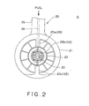
- Figs. 1 and 2 show a fuel injection device A for a gas turbine to which a fuel supply method and a fuel supply system in preferred embodiments according to the present invention are applied.
- the fuel injection device A includes, as principal components, a fuel injection unit 10 that provides a combustion chamber (not shown) with an air fuel mixture, and a holding-and-supplying unit 20 that holds the fuel injection unit 10.
- the fuel injection unit 10 includes a first fuel injection member 30 disposed in a central part of the fuel injection unit 10, a first atomizing mechanism 40 surrounding the first fuel injection member 30 and capable of atomizing fuel injected from the first fuel injection member 30, a second fuel injection member 50 surrounding the first atomizing mechanism 40, a second atomizing mechanism 60 surrounding the second fuel injection member 50 and capable of atomizing fuel injected from the second fuel injection member 50, and an outer casing 70 surrounding the second atomizing mechanism 60.
- the first fuel injection member 30 has a cylindrical shape and is provided with a fuel supply passage 31 extended coaxially with the first fuel injection member 30 from a base end part to a middle part of the first fuel injection member 30, and a fuel reservoir 32.
- the fuel reservoir has a side wall provided with a predetermined number of radial fuel jetting holes 33 arranged on a circle.
- a joining part 34 is formed on the base end part of the first fuel injection member 30.
- the joining part 34 is joined to the holding-and-supplying unit 20.
- a reduced part 34a is formed at the base end part of the first fuel injection member 30 as shown in Fig. 1.
- the second fuel injection member 50 has the shape of a cylindrical tube and is provided with a fuel reservoir 51.
- the fuel reservoir 51 has a side wall provided with a predetermined number of radial fuel jetting holes 52 arranged on a circle.
- a joining part 55 is formed on the base end part of the second fuel injection member 50.
- the joining part 55 is joined to the holding-and-supplying unit 20.
- a projection of a predetermined length is formed in the base end part of the second fuel injection member 50 as shown in Fig. 1.
- the first atomizing mechanism 40 has an annular air passage 41 defined by the outer circumference of the first fuel injection member 30 and the inner circumference of the second fuel injection member 50, and an air swirling mechanism 43 disposed between the first fuel injection member 30 and the second fuel injection member 50.
- the second atomizing mechanism 60 has an annular air passage 61 defined by the outer circumference of the second fuel injection member 50 and the inner circumference of the outer casing 70, and an air swirling mechanism 63 disposed between the second fuel injection member 50 and the outer casing 70.
- the holding-and-supplying unit 20 has an outer ring 21 joined to the outer casing 70, an inner ring 22 joined to the second fuel injection member 50, a central cylindrical part 23 joined to the first fuel injection member 30, a fuel feed arm 26 formed integrally with the outer ring 21, and a combining structure 25 connecting those components 21, 22, 23 and 26.
- Fuel passages 28 are formed through the fuel feed arm 26 so as to be connected to fuel passages penetrating a gas turbine casing. Combustion air is supplied through the space between the inner ring 22 and the central cylindrical part 23 to the first atomizing mechanism 40, and combustion air is supplied through the space between the outer ring 21 and the inner ring 22 to the second atomizing mechanism 60.
- the inner ring 22 is provided with an annular groove 22a of a predetermined depth formed in a shape corresponding to that of the base end part of the second fuel injection member 50 in its surface facing the second fuel injection member 50.
- a fuel supply hole 22b is formed in the annular groove 22a.
- a fuel supply passage 27 (second fuel supply passage 27b) is formed through the fuel feed arm 26 and the combining structure 25 and is connected to the fuel supply hole 22b.
- the central cylindrical part 23 is provided with a recess 23a of a predetermined depth having a shape corresponding to that of the base end part of the first fuel injection member 30 as shown in Fig. 1.
- a fuel supply passage 27 (first fuel supply passage 27a) formed through the fuel feed arm 26 and the combining structure 25 opens into the bottom of the recess 23a.
- the combining structure 25 has an upper connecting part 25a connecting the inner ring 22 to an upper part of the outer ring 21, a central connecting part 25b connecting the inner ring 22 and the central cylindrical part 23, and a lower connecting part 25c connecting the inner ring 22 to a lower part of the outer ring 21.
- the fuel supply passages 27 connected to the fuel supply passages 28 of the fuel feed arm 26 are extended in the combining structure 25.
- the first fuel supply passage 27a and the second fuel supply passage 27b formed in the upper connecting part 25a and the central connecting part 25b are arranged so as to overlap each other with respect to a direction in which combustion air flows as shown in Fig.
- each of the upper connecting part 25a, the central connecting part 25b and the lower connecting part 25c in the least necessary width, i.e., a dimension along the direction perpendicular to the direction in which combustion air flows.
- the increase of blockage of the air flowing into combustor and un-uniformity in air flowing into combustor caused by the upper connecting part 25a, the central connecting part 25b and the lower connecting part 25c can be limited to the least unavoidable extent.
- the words upper and lower are used for designating upper and lower parts as viewed in Figs. 1 and 2 for convenience and do not necessarily designate upper and lower parts on the combustor of an actual gas turbine.
- the fuel injection device A jets fuel only by the first fuel injection member 30, atomizes the jetted fuel by the first atomizing mechanism 40, and supplies an air-fuel mixture into combustion chamber while the gas turbine is operating in low-power settings.
- the fuel injection device A jets fuel by both the first fuel injection member 30 and the second fuel injection member 50, atomizes the jetted fuel by the first atomizing mechanism 40 and the second atomizing mechanism 60, and supplies an air-fuel mixture into combustion chamber while the gas turbine is operating in a high-power settings.
- the fuel supply passages 27 are formed in the holding-and-supplying unit 20 holding the fuel injection unit 10 and are connected to the fuel passages 28 formed in the fuel feed arm 26 combined with the holding-and-supplying unit 20. Therefore, any additional fuel supply pipes are not necessary, and hence the fuel supply system has simple construction. Since any fuel supply pipes are not necessary, the fuel supply system is free from troubles attributable to laying fuel supply pipes. For example, preventive means for preventing the breakage of fuel supply pipes liable to occur in installing a fuel supply system are unnecessary, and hence the fuel supply system can be efficiently assembled. The fuel supply system is free from troubles due to the difference in thermal expansion between fuel supply pipes and a supporting part.
- the fuel supply system may be provided with a third fuel injection member surrounding the second fuel injection member 50 in addition to the first fuel injection member 30 and the second fuel injection member 50.
- the fuel injection device A is disposed under the annular combustor instead of over the combustor as mentioned above, "upper” and “lower” used in the foregoing description are replaced with “lower” and “upper”, respectively.
Landscapes
- Engineering & Computer Science (AREA)
- Chemical & Material Sciences (AREA)
- Combustion & Propulsion (AREA)
- Mechanical Engineering (AREA)
- General Engineering & Computer Science (AREA)
Applications Claiming Priority (4)
| Application Number | Priority Date | Filing Date | Title |
|---|---|---|---|
| JP2003430408 | 2003-12-25 | ||
| JP2003430408A JP3845802B2 (ja) | 2003-12-25 | 2003-12-25 | 燃料噴射装置への燃料供給機構 |
| JP2004012585A JP3840560B2 (ja) | 2004-01-21 | 2004-01-21 | 燃料供給方法および燃料供給装置 |
| JP2004012585 | 2004-01-21 |
Publications (2)
| Publication Number | Publication Date |
|---|---|
| EP1548361A1 true EP1548361A1 (de) | 2005-06-29 |
| EP1548361B1 EP1548361B1 (de) | 2016-04-27 |
Family
ID=34554867
Family Applications (2)
| Application Number | Title | Priority Date | Filing Date |
|---|---|---|---|
| EP04251906.6A Expired - Lifetime EP1548361B1 (de) | 2003-12-25 | 2004-03-30 | Kraftstoffversorgungsverfahren und Kraftstoffzufuhrsystem |
| EP04251907.4A Expired - Lifetime EP1548362B1 (de) | 2003-12-25 | 2004-03-30 | Kraftstoffzufuhrverfahren und Vorrichtung für Kraftstoffeinspritzeinrichtung |
Family Applications After (1)
| Application Number | Title | Priority Date | Filing Date |
|---|---|---|---|
| EP04251907.4A Expired - Lifetime EP1548362B1 (de) | 2003-12-25 | 2004-03-30 | Kraftstoffzufuhrverfahren und Vorrichtung für Kraftstoffeinspritzeinrichtung |
Country Status (2)
| Country | Link |
|---|---|
| US (2) | US7225996B2 (de) |
| EP (2) | EP1548361B1 (de) |
Families Citing this family (4)
| Publication number | Priority date | Publication date | Assignee | Title |
|---|---|---|---|---|
| EP2085695A1 (de) * | 2008-01-29 | 2009-08-05 | Siemens Aktiengesellschaft | Brennstoffdüse mit Drallkanal und Verfahren zur Herstellung einer Brennstoffdüse |
| US8225610B2 (en) * | 2008-12-08 | 2012-07-24 | General Electric Company | Fuel delivery system and method of assembling the same |
| GB0918169D0 (en) * | 2009-10-19 | 2009-12-02 | Rolls Royce Plc | Fuel injector mounting system |
| US9027350B2 (en) * | 2009-12-30 | 2015-05-12 | Rolls-Royce Corporation | Gas turbine engine having dome panel assembly with bifurcated swirler flow |
Citations (5)
| Publication number | Priority date | Publication date | Assignee | Title |
|---|---|---|---|---|
| US3684186A (en) | 1970-06-26 | 1972-08-15 | Ex Cell O Corp | Aerating fuel nozzle |
| US3912164A (en) * | 1971-01-11 | 1975-10-14 | Parker Hannifin Corp | Method of liquid fuel injection, and to air blast atomizers |
| US5577386A (en) * | 1994-06-20 | 1996-11-26 | Societe Nationale D'etude Et De Construction De Moteurs D'aviation S.N.E.C.M.A. | System for cooling a high power fuel injector of a dual injector |
| US6082113A (en) * | 1998-05-22 | 2000-07-04 | Pratt & Whitney Canada Corp. | Gas turbine fuel injector |
| EP1369644A1 (de) * | 2002-06-04 | 2003-12-10 | General Electric Company | Laminierte Brennstofflamelle einer Brennstoffeinspritzdüse |
Family Cites Families (22)
| Publication number | Priority date | Publication date | Assignee | Title |
|---|---|---|---|---|
| US2408136A (en) * | 1942-12-07 | 1946-09-24 | E & J Mfg Company | Resuscitator insufflator aspirator |
| GB686383A (en) | 1949-06-27 | 1953-01-21 | Rolls Royce | Improvements in or relating to gas-turbine engines |
| CH525386A (it) * | 1969-03-26 | 1972-07-15 | Atomjuboll S R L | Carburatore con pompetta ausiliaria del carburante per motori a combustione interna |
| FR2320082A1 (fr) * | 1975-08-07 | 1977-03-04 | Assistance Tech Med | Respirateur pour le traitement d'insuffisants respiratoires, utilisable plus particulierement a domicile |
| IL52690A (en) * | 1977-08-09 | 1982-03-31 | Yeda Res & Dev | Apparatus for controlled heating of the nasal passages |
| US4360017A (en) * | 1981-03-18 | 1982-11-23 | Harry Barlett | Mouthpiece for resuscitation |
| GB2096468B (en) * | 1981-04-03 | 1984-11-14 | Yeda Res & Dev | Improvement in or relating to an apparatus for medical treatment |
| US4674494A (en) * | 1985-05-10 | 1987-06-23 | The Kendall Company | Humidifying device |
| US4770168A (en) * | 1985-12-16 | 1988-09-13 | Tibor Rusz | Electrically controllable anesthesia vaporizer |
| NZ226784A (en) * | 1988-09-29 | 1992-10-28 | Fisher & Paykel | Gas humidifier with microporous wall |
| US5178115A (en) * | 1991-02-11 | 1993-01-12 | Siemens Automotive L.P. | Fuel rail assembly having self-contained electronics |
| SE503089C2 (sv) * | 1991-09-20 | 1996-03-25 | Gibeck Respiration Ab | Anordning för anslutning av en patient till en respirator innefattande en fuktvärmeväxlare samt användning av en fuktvärmeväxlare i denna anordning |
| US5197288A (en) * | 1991-12-06 | 1993-03-30 | United Technologies Corporation | Detachable fuel manifold for gas turbine engines |
| US6814714B1 (en) * | 1993-06-15 | 2004-11-09 | Storz Endoskop Gmbh | Instrument that can be inserted into the human body |
| EP0967382B1 (de) * | 1998-06-24 | 2004-11-24 | Delphi Technologies, Inc. | Brennstoffeinspritzdüse |
| EP1041272B1 (de) * | 1999-04-01 | 2004-10-27 | Delphi Technologies, Inc. | Brennstoffeinspritzventil |
| US6338445B1 (en) * | 1999-10-06 | 2002-01-15 | Delphi Technologies, Inc. | Fuel injector |
| US6256995B1 (en) * | 1999-11-29 | 2001-07-10 | Pratt & Whitney Canada Corp. | Simple low cost fuel nozzle support |
| US6540162B1 (en) * | 2000-06-28 | 2003-04-01 | General Electric Company | Methods and apparatus for decreasing combustor emissions with spray bar assembly |
| US6363726B1 (en) | 2000-09-29 | 2002-04-02 | General Electric Company | Mixer having multiple swirlers |
| US6484489B1 (en) * | 2001-05-31 | 2002-11-26 | General Electric Company | Method and apparatus for mixing fuel to decrease combustor emissions |
| US6637675B2 (en) * | 2001-07-13 | 2003-10-28 | Cummins Inc. | Rate shaping fuel injector with limited throttling |
-
2004
- 2004-03-26 US US10/809,693 patent/US7225996B2/en not_active Expired - Lifetime
- 2004-03-26 US US10/809,692 patent/US7104464B2/en not_active Expired - Lifetime
- 2004-03-30 EP EP04251906.6A patent/EP1548361B1/de not_active Expired - Lifetime
- 2004-03-30 EP EP04251907.4A patent/EP1548362B1/de not_active Expired - Lifetime
Patent Citations (5)
| Publication number | Priority date | Publication date | Assignee | Title |
|---|---|---|---|---|
| US3684186A (en) | 1970-06-26 | 1972-08-15 | Ex Cell O Corp | Aerating fuel nozzle |
| US3912164A (en) * | 1971-01-11 | 1975-10-14 | Parker Hannifin Corp | Method of liquid fuel injection, and to air blast atomizers |
| US5577386A (en) * | 1994-06-20 | 1996-11-26 | Societe Nationale D'etude Et De Construction De Moteurs D'aviation S.N.E.C.M.A. | System for cooling a high power fuel injector of a dual injector |
| US6082113A (en) * | 1998-05-22 | 2000-07-04 | Pratt & Whitney Canada Corp. | Gas turbine fuel injector |
| EP1369644A1 (de) * | 2002-06-04 | 2003-12-10 | General Electric Company | Laminierte Brennstofflamelle einer Brennstoffeinspritzdüse |
Also Published As
| Publication number | Publication date |
|---|---|
| US7225996B2 (en) | 2007-06-05 |
| US7104464B2 (en) | 2006-09-12 |
| EP1548361B1 (de) | 2016-04-27 |
| US20050139694A1 (en) | 2005-06-30 |
| EP1548362A1 (de) | 2005-06-29 |
| US20050139695A1 (en) | 2005-06-30 |
| EP1548362B1 (de) | 2015-05-27 |
Similar Documents
| Publication | Publication Date | Title |
|---|---|---|
| CN100552300C (zh) | 用于燃烧器的同心的固定稀释及可变的旁路空气喷射 | |
| US9046039B2 (en) | Staged pilots in pure airblast injectors for gas turbine engines | |
| EP2711628B1 (de) | Gasturbinenbrennkammer mit flammformgebenden Luftzufuhrlöchern | |
| US8677760B2 (en) | Fuel nozzle with integrated passages and method of operation | |
| US8113001B2 (en) | Tubular fuel injector for secondary fuel nozzle | |
| US6374615B1 (en) | Low cost, low emissions natural gas combustor | |
| EP2405201B1 (de) | Einspritzdüse für eine Turbomaschine | |
| US6786046B2 (en) | Dual-mode nozzle assembly with passive tip cooling | |
| US6857271B2 (en) | Secondary fuel nozzle with readily customizable pilot fuel flow rate | |
| US20050000222A1 (en) | Gas turbine combustor and operating method thereof | |
| US20060010878A1 (en) | Method of cooling centerbody of premixing burner | |
| US10125992B2 (en) | Gas turbine combustor with annular flow sleeves for dividing airflow upstream of premixing passages | |
| JP2015534632A (ja) | 改良された操作性のための半径方向に段付けされた予混合されるパイロットを備える燃焼器 | |
| JP2009109180A (ja) | 希薄予混合半径方向流入マルチアニュラ多段ノズルの缶アニュラ型デュアル燃料燃焼器 | |
| CN206973617U (zh) | 先导预混合喷嘴和燃料喷嘴组件 | |
| US20210180518A1 (en) | Gas Turbine Combustor | |
| EP2592351B1 (de) | Gestufte Pilotbrenner in reinen Drucklufteinspritzdüsen für Gasturbinenmotoren | |
| JP3192055B2 (ja) | ガスタービン燃焼器 | |
| JP2000356315A (ja) | ガスタービンの燃焼器用バーナ装置 | |
| US7104464B2 (en) | Fuel supply method and fuel supply system | |
| JPH07248118A (ja) | 予混合燃焼器 | |
| JP3840560B2 (ja) | 燃料供給方法および燃料供給装置 | |
| US20050274827A1 (en) | Flow restriction device for a fuel nozzle assembly | |
| JP3845802B2 (ja) | 燃料噴射装置への燃料供給機構 | |
| JP2004053209A (ja) | ガスタービン燃焼器 |
Legal Events
| Date | Code | Title | Description |
|---|---|---|---|
| PUAI | Public reference made under article 153(3) epc to a published international application that has entered the european phase |
Free format text: ORIGINAL CODE: 0009012 |
|
| 17P | Request for examination filed |
Effective date: 20040421 |
|
| AK | Designated contracting states |
Kind code of ref document: A1 Designated state(s): AT BE BG CH CY CZ DE DK EE ES FI FR GB GR HU IE IT LI LU MC NL PL PT RO SE SI SK TR |
|
| AX | Request for extension of the european patent |
Extension state: AL LT LV MK |
|
| AKX | Designation fees paid |
Designated state(s): DE FR GB |
|
| 17Q | First examination report despatched |
Effective date: 20070208 |
|
| GRAP | Despatch of communication of intention to grant a patent |
Free format text: ORIGINAL CODE: EPIDOSNIGR1 |
|
| INTG | Intention to grant announced |
Effective date: 20151013 |
|
| GRAS | Grant fee paid |
Free format text: ORIGINAL CODE: EPIDOSNIGR3 |
|
| RIN1 | Information on inventor provided before grant (corrected) |
Inventor name: KOBAYASHI, MASAYOSHI Inventor name: ODA, TAKEO Inventor name: MIYAMOTO, HIROAKI Inventor name: NINOMIYA, HIROYUKI |
|
| GRAA | (expected) grant |
Free format text: ORIGINAL CODE: 0009210 |
|
| AK | Designated contracting states |
Kind code of ref document: B1 Designated state(s): DE FR GB |
|
| REG | Reference to a national code |
Ref country code: GB Ref legal event code: FG4D |
|
| REG | Reference to a national code |
Ref country code: DE Ref legal event code: R096 Ref document number: 602004049151 Country of ref document: DE |
|
| REG | Reference to a national code |
Ref country code: DE Ref legal event code: R097 Ref document number: 602004049151 Country of ref document: DE |
|
| PLBE | No opposition filed within time limit |
Free format text: ORIGINAL CODE: 0009261 |
|
| STAA | Information on the status of an ep patent application or granted ep patent |
Free format text: STATUS: NO OPPOSITION FILED WITHIN TIME LIMIT |
|
| REG | Reference to a national code |
Ref country code: FR Ref legal event code: PLFP Year of fee payment: 14 |
|
| 26N | No opposition filed |
Effective date: 20170130 |
|
| REG | Reference to a national code |
Ref country code: FR Ref legal event code: PLFP Year of fee payment: 15 |
|
| PGFP | Annual fee paid to national office [announced via postgrant information from national office to epo] |
Ref country code: FR Payment date: 20230208 Year of fee payment: 20 |
|
| PGFP | Annual fee paid to national office [announced via postgrant information from national office to epo] |
Ref country code: GB Payment date: 20230209 Year of fee payment: 20 Ref country code: DE Payment date: 20230131 Year of fee payment: 20 |
|
| REG | Reference to a national code |
Ref country code: DE Ref legal event code: R071 Ref document number: 602004049151 Country of ref document: DE |
|
| REG | Reference to a national code |
Ref country code: GB Ref legal event code: PE20 Expiry date: 20240329 |
|
| PG25 | Lapsed in a contracting state [announced via postgrant information from national office to epo] |
Ref country code: GB Free format text: LAPSE BECAUSE OF EXPIRATION OF PROTECTION Effective date: 20240329 |