EP1548380A2 - Flachrohrverdampfer mit Mikroverteiler - Google Patents
Flachrohrverdampfer mit Mikroverteiler Download PDFInfo
- Publication number
- EP1548380A2 EP1548380A2 EP04258010A EP04258010A EP1548380A2 EP 1548380 A2 EP1548380 A2 EP 1548380A2 EP 04258010 A EP04258010 A EP 04258010A EP 04258010 A EP04258010 A EP 04258010A EP 1548380 A2 EP1548380 A2 EP 1548380A2
- Authority
- EP
- European Patent Office
- Prior art keywords
- flat
- tube
- inlet manifold
- distributor
- refrigerant
- Prior art date
- Legal status (The legal status is an assumption and is not a legal conclusion. Google has not performed a legal analysis and makes no representation as to the accuracy of the status listed.)
- Withdrawn
Links
Images


Classifications
-
- F—MECHANICAL ENGINEERING; LIGHTING; HEATING; WEAPONS; BLASTING
- F28—HEAT EXCHANGE IN GENERAL
- F28D—HEAT-EXCHANGE APPARATUS, NOT PROVIDED FOR IN ANOTHER SUBCLASS, IN WHICH THE HEAT-EXCHANGE MEDIA DO NOT COME INTO DIRECT CONTACT
- F28D1/00—Heat-exchange apparatus having stationary conduit assemblies for one heat-exchange medium only, the media being in contact with different sides of the conduit wall, in which the other heat-exchange medium is a large body of fluid, e.g. domestic or motor car radiators
- F28D1/02—Heat-exchange apparatus having stationary conduit assemblies for one heat-exchange medium only, the media being in contact with different sides of the conduit wall, in which the other heat-exchange medium is a large body of fluid, e.g. domestic or motor car radiators with heat-exchange conduits immersed in the body of fluid
- F28D1/04—Heat-exchange apparatus having stationary conduit assemblies for one heat-exchange medium only, the media being in contact with different sides of the conduit wall, in which the other heat-exchange medium is a large body of fluid, e.g. domestic or motor car radiators with heat-exchange conduits immersed in the body of fluid with tubular conduits
- F28D1/053—Heat-exchange apparatus having stationary conduit assemblies for one heat-exchange medium only, the media being in contact with different sides of the conduit wall, in which the other heat-exchange medium is a large body of fluid, e.g. domestic or motor car radiators with heat-exchange conduits immersed in the body of fluid with tubular conduits the conduits being straight
- F28D1/0535—Heat-exchange apparatus having stationary conduit assemblies for one heat-exchange medium only, the media being in contact with different sides of the conduit wall, in which the other heat-exchange medium is a large body of fluid, e.g. domestic or motor car radiators with heat-exchange conduits immersed in the body of fluid with tubular conduits the conduits being straight the conduits having a non-circular cross-section
- F28D1/05366—Assemblies of conduits connected to common headers, e.g. core type radiators
-
- F—MECHANICAL ENGINEERING; LIGHTING; HEATING; WEAPONS; BLASTING
- F25—REFRIGERATION OR COOLING; COMBINED HEATING AND REFRIGERATION SYSTEMS; HEAT PUMP SYSTEMS; MANUFACTURE OR STORAGE OF ICE; LIQUEFACTION SOLIDIFICATION OF GASES
- F25B—REFRIGERATION MACHINES, PLANTS OR SYSTEMS; COMBINED HEATING AND REFRIGERATION SYSTEMS; HEAT PUMP SYSTEMS
- F25B39/00—Evaporators; Condensers
- F25B39/02—Evaporators
- F25B39/022—Evaporators with plate-like or laminated elements
-
- F—MECHANICAL ENGINEERING; LIGHTING; HEATING; WEAPONS; BLASTING
- F25—REFRIGERATION OR COOLING; COMBINED HEATING AND REFRIGERATION SYSTEMS; HEAT PUMP SYSTEMS; MANUFACTURE OR STORAGE OF ICE; LIQUEFACTION SOLIDIFICATION OF GASES
- F25B—REFRIGERATION MACHINES, PLANTS OR SYSTEMS; COMBINED HEATING AND REFRIGERATION SYSTEMS; HEAT PUMP SYSTEMS
- F25B39/00—Evaporators; Condensers
- F25B39/02—Evaporators
- F25B39/028—Evaporators having distributing means
-
- F—MECHANICAL ENGINEERING; LIGHTING; HEATING; WEAPONS; BLASTING
- F25—REFRIGERATION OR COOLING; COMBINED HEATING AND REFRIGERATION SYSTEMS; HEAT PUMP SYSTEMS; MANUFACTURE OR STORAGE OF ICE; LIQUEFACTION SOLIDIFICATION OF GASES
- F25B—REFRIGERATION MACHINES, PLANTS OR SYSTEMS; COMBINED HEATING AND REFRIGERATION SYSTEMS; HEAT PUMP SYSTEMS
- F25B5/00—Compression machines, plants or systems, with several evaporator circuits, e.g. for varying refrigerating capacity
- F25B5/02—Compression machines, plants or systems, with several evaporator circuits, e.g. for varying refrigerating capacity arranged in parallel
-
- F—MECHANICAL ENGINEERING; LIGHTING; HEATING; WEAPONS; BLASTING
- F28—HEAT EXCHANGE IN GENERAL
- F28F—DETAILS OF HEAT-EXCHANGE AND HEAT-TRANSFER APPARATUS, OF GENERAL APPLICATION
- F28F9/00—Casings; Header boxes; Auxiliary supports for elements; Auxiliary members within casings
- F28F9/02—Header boxes; End plates
- F28F9/026—Header boxes; End plates with static flow control means, e.g. with means for uniformly distributing heat exchange media into conduits
- F28F9/027—Header boxes; End plates with static flow control means, e.g. with means for uniformly distributing heat exchange media into conduits in the form of distribution pipes
- F28F9/0273—Header boxes; End plates with static flow control means, e.g. with means for uniformly distributing heat exchange media into conduits in the form of distribution pipes with multiple holes
-
- F—MECHANICAL ENGINEERING; LIGHTING; HEATING; WEAPONS; BLASTING
- F25—REFRIGERATION OR COOLING; COMBINED HEATING AND REFRIGERATION SYSTEMS; HEAT PUMP SYSTEMS; MANUFACTURE OR STORAGE OF ICE; LIQUEFACTION SOLIDIFICATION OF GASES
- F25B—REFRIGERATION MACHINES, PLANTS OR SYSTEMS; COMBINED HEATING AND REFRIGERATION SYSTEMS; HEAT PUMP SYSTEMS
- F25B2400/00—Component parts or details not otherwise provided for in this subclass
- F25B2400/22—Refrigeration systems for supermarkets
-
- F—MECHANICAL ENGINEERING; LIGHTING; HEATING; WEAPONS; BLASTING
- F25—REFRIGERATION OR COOLING; COMBINED HEATING AND REFRIGERATION SYSTEMS; HEAT PUMP SYSTEMS; MANUFACTURE OR STORAGE OF ICE; LIQUEFACTION SOLIDIFICATION OF GASES
- F25B—REFRIGERATION MACHINES, PLANTS OR SYSTEMS; COMBINED HEATING AND REFRIGERATION SYSTEMS; HEAT PUMP SYSTEMS
- F25B2500/00—Problems to be solved
- F25B2500/01—Geometry problems, e.g. for reducing size
-
- F—MECHANICAL ENGINEERING; LIGHTING; HEATING; WEAPONS; BLASTING
- F28—HEAT EXCHANGE IN GENERAL
- F28D—HEAT-EXCHANGE APPARATUS, NOT PROVIDED FOR IN ANOTHER SUBCLASS, IN WHICH THE HEAT-EXCHANGE MEDIA DO NOT COME INTO DIRECT CONTACT
- F28D21/00—Heat-exchange apparatus not covered by any of the groups F28D1/00 - F28D20/00
- F28D2021/0019—Other heat exchangers for particular applications; Heat exchange systems not otherwise provided for
- F28D2021/0068—Other heat exchangers for particular applications; Heat exchange systems not otherwise provided for for refrigerant cycles
- F28D2021/0071—Evaporators
Definitions
- This invention relates generally to heat exchangers, and more particularly to evaporators.
- supermarkets and convenience stores are equipped with refrigerated merchandisers, reach-in coolers, and/or unit coolers for presenting food and/or beverage products to customers while maintaining the food and/or beverage products in a refrigerated environment.
- cold, moisture-bearing air is provided to a product display area of the merchandiser, reach-in cooler, and/or unit cooler by passing an airflow over the heat exchange surface of an evaporator coil, or evaporator.
- a suitable refrigerant is passed through the evaporator to act as a heat exchange medium.
- the refrigerant absorbs heat from the airflow through the evaporator, and as the heat exchange takes place, the refrigerant evaporates while passing through the evaporator.
- the temperature of the airflow through the evaporator is lowered for introduction into the product display area of the merchandiser, reach-in cooler, and/or unit cooler.
- the present invention provides, in one aspect, a flat-tube evaporator with a micro-distributor.
- the micro-distributor includes a tube having an inlet and an outlet comprised of a plurality of orifices in the tube.
- the tube is at least partially positioned in an inlet manifold of the flat-tube evaporator to enhance distribution of refrigerant from the tube to the inlet manifold of the flat-tube evaporator.
- the present invention provides, in another aspect, a refrigeration system including one or more flat-tube evaporators connected in parallel, each having a micro-distributor.
- the refrigeration system may also include a distributor in a fluid series connection with the micro-distributors of the flat-tube evaporators.
- a flat-tube evaporator can include an inlet manifold, an outlet manifold separated a distance from the inlet manifold, a distributor tube positioned within the inlet manifold and fluidly connected to a source of refrigerant, and a plurality of flat tubes fluidly connecting the inlet manifold and the outlet manifold.
- the distributor tube can include a plurality of orifices arranged in a substantially linear configuration along the length of the distributor tube, each of the plurality of orifices directing refrigerant into the inlet manifold in a first direction.
- Each of the plurality of flat tubes can define a second direction of fluid flow from the inlet manifold to the outlet manifold, the second direction being substantially opposite to the first direction.
- a flat-tube evaporator in some embodiments, is provided.
- the flat-tube evaporator an include an inlet manifold, an outlet manifold separated a distance from the inlet manifold, a distributor tube positioned within the inlet manifold and in fluid communication with a refrigerant source, and a plurality of flat tubes positioned to fluidly connect the inlet manifold and the outlet manifold.
- the distributor tube can include a plurality of orifices through which refrigerant is directed into the inlet manifold.
- the plurality of orifices can be arranged to direct refrigerant into the inlet manifold in a first direction, wherein refrigerant is substantially only directed from the distributor tube into the inlet manifold in the first direction.
- the plurality of flat tubes can be positioned to direct the refrigerant from the inlet manifold to the outlet manifold in a second direction, the second direction being substantially opposite the first direction.
- a refrigeration system can include a common distributor fluidly connected to a refrigerant source, and a plurality of flat-tube evaporators.
- Each of the plurality of flat-tube evaporators can include an inlet manifold, an outlet manifold separated a distance from the inlet manifold, a distributor tube positioned within the inlet manifold and fluidly connected to the common distributor, and a plurality of flat tubes positioned to fluidly connect the inlet manifold and the outlet manifold.
- the distributor tube can include a plurality of orifices positioned along the length of the distributor tube, each of the plurality of orifices positioned to direct the refrigerant into the inlet manifold in a first direction.
- Each of the plurality of flat tubes can be positioned to direct the refrigerant from the inlet manifold to the outlet manifold in a second direction, the second direction being substantially opposite the first direction.
- FIG. 1 is a perspective view of a refrigerated merchandiser utilizing a flat-tube evaporator.
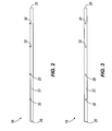
- FIG. 2 is a plan view of a micro-distributor for use in the flat-tube evaporator, illustrating the flow of refrigerant from a plurality of orifices.
- FIG. 3 is a side view of the micro-distributor of FIG. 2.
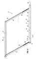
- FIG. 4 is a perspective view of the micro-distributor of FIG. 2 positioned in an inlet manifold of the flat-tube evaporator.
- FIG. 5 is a perspective view of a plurality of flat-tube evaporators connected in parallel, each flat-tube evaporator having a micro-distributor of FIG. 2 connected in series with a distributor.
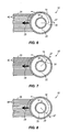
- FIG. 6 is a cross-sectional view of the flat-tube evaporator of FIG. 4, taken along line 6-6.
- FIG. 7 is a cross-sectional view of a flat-tube evaporator according to another embodiment of the invention.
- FIG. 8 is a cross-sectional view of a flat-tube evaporator according to another embodiment of the invention.
- refrigerated merchandisers, reach-in coolers, and/or unit coolers utilize long spans (upwards of 12') of round-tube plate-fin evaporators (not shown) to span the length of the refrigerated space of the refrigerated merchandisers, reach-in coolers, and/or unit coolers.
- the long spans of round-tube plate-fin evaporators may be replaced with one or more flat-tube evaporators 10 in an effort to improve upon the performance and/or efficiency of the refrigeration system of the refrigerated merchandisers, reach-in coolers, and/or unit coolers.
- FIG. 1 illustrates an exemplary refrigerated merchandiser 100 utilizing the flat-tube evaporator 10.
- FIG. 1 illustrates the flat-tube evaporator 10 in one particular orientation in the merchandiser 100, such that refrigerant flows across the flat-tube evaporator 10 in a substantially horizontal direction
- other constructions of the merchandiser 100 may orient the flat-tube evaporator 10 in any of a number of different orientations such that the refrigerant flows in any of a number of different directions.
- other constructions of the merchandiser 100 may also be employed with the flat-tube evaporator 10.
- flat-tube evaporators 10 offer better performance than conventional round-tube plate-fin evaporators.
- flat-tube evaporators 10 may achieve a refrigerant-side pressure drop as low as about 0.67 psi, compared to the 2 psi refrigerant-side pressure drop of conventional round-tube plate-fin evaporators.
- a lower refrigerant-side pressure drop allows the refrigerant to more easily move throughout the evaporator 10.
- flat-tube evaporators 10 may achieve an air-side pressure drop as low as about 0.03 inwg (inches of water column gauge), compared to the 0.07 inwg pressure drop of conventional round-tube plate-fin evaporators.
- flat-tube evaporator 10 having a relatively large face area. A lower air-side pressure drop allows the fan power to be reduced.
- flat-tube evaporators 10 may allow for an approach temperature as low as about 1° F. The approach temperature is defined as the difference between the temperature of the discharged airflow and the saturation temperature of the refrigerant passing through the evaporator 10.
- Conventional round-tube plate-fin evaporators are less efficient than the flat-tube evaporator. As a result, the costs associated with operating a merchandiser 100 utilizing the flat-tube evaporator 10 may be substantially lower than the costs associated with operating a merchandiser utilizing a conventional round-tube plate-fin evaporator.
- FIGS. 2 and 3 illustrate a distributor tube or micro-distributor 18 for use with flat-tube evaporators 10 in an effort to decrease the maldistribution of two-phase refrigerant in flat-tube evaporators 10.
- the micro-distributor 18 includes a tube 22 having an inlet 26 and an outlet comprised of a plurality of orifices 30 therein.
- the plurality of orifices 30 comprise a plurality of apertures, or holes in the tube 22.
- the lines corresponding with the orifices 30 are for reference purposes only and do not indicate any additional structure corresponding with the orifices 30.
- a plurality of outlets e.g., straight-tubes, nozzles, diffusers, etc.
- a plurality of outlets corresponding with the orifices 30 may be used.
- Refrigerant may enter the tube 22 via the inlet 26, while an end 28 of the tube 22 opposite the inlet 26 may be blocked or closed to force discharge of the refrigerant through the orifices 30.
- the orifices 30 are sized appropriately to cause a pressure increase or build-up in the tube 22.
- the build-up of pressure in the tube 22 causes the refrigerant to substantially equally distribute along the length of the tube 22.
- the tube 22 and orifices 30 are also sized appropriately to reduce the amount of separation of vapor refrigerant and liquid refrigerant in the two-phase flow.
- the orifices 30 are aligned in the tube 22 in a substantially linear configuration.
- alternate constructions of the micro-distributor 18 may include orifices 30 in the tube 22 in a curvlinear configuration, or orifices 30 substantially arranged about the circumference of the tube 22 in any of a number of different patterns or random configurations.
- the orifices 30 are substantially equally-spaced from one another.
- alternate constructions of the micro-distributor 18 may include orifices 30 having different concentrations or spacing along the length of the tube 22.
- the tube 22 utilizes a relatively small diameter (i.e., an internal diameter) of about 3/16" to 1/4".
- the tube 22 may have a diameter of at least about 1/4".
- the tube 22 may have a diameter of at least about 1/8".
- the tube 22 may have a diameter less than about 1/2".
- the tube 22 may have a diameter less than about 1/4".
- Alternate constructions of the micro-distributor 18 may also include a tube 22 having a non-circular cross-sectional shape of nominal size corresponding to the circular cross-sectional tube 22.
- the micro-distributor 18 includes orifices 30 having a diameter of about 0.032".
- the orifices 30 may have a diameter of at least about 0.020".
- the orifices 30 may have a diameter of at least about 0.050".
- the orifices 30 may have a diameter less than about 0.150".
- the orifices 30 in the tube 22 may have a diameter less than about 0.050".
- Alternate constructions of the micro-distributor 18 may also include orifices 30 having a non-circular shape of nominal size corresponding to the circular orifices 30.
- FIG. 4 illustrates the micro-distributor 18 positioned substantially in the inlet manifold 14 of the flat-tube evaporator 10. Portions of the flat-tube evaporator 10 (e.g., the flat tubes and fins) are substantially removed for purposes of clarity.
- the inlet manifold 14 is substantially sealed such that refrigerant is fed to the micro-distributor 18, and discharged from the micro-distributor 18 via the orifices 30 into the inlet manifold 14.
- the flat-tube evaporator 10 also includes an outlet manifold 34 fluidly connected to the inlet manifold 14 by a plurality of flat tubes 38.
- the flat-tubes 38 may be formed to include a plurality of internal passageways, or microchannels 40 (as shown in FIG. 6), that are much smaller in size than the internal passageway of the coil in a round-tube plate-fin evaporator.
- the flat tubes 38 may also comprise mini multi-port tubes, or micro multi-port tubes (otherwise known as microchannel tubes).
- the tubes 38 may include only one channel, or internal passageway.
- the flat tubes 38, the inlet manifold 14, and the outlet manifold 34 are made from a highly conductive metal such as aluminum, however other highly conductive metals may also be used.
- the flat tubes 38 are coupled to the inlet manifold 14 and the outlet manifold 34 by a brazing process, however, a welding process may also be used.
- the microchannels 40 allow for more efficient heat transfer between the airflow passing over the flat-tubes 38 and the refrigerant carried within the microchannels 40, compared to the airflow passing over the coil of the round-tube plate-fin evaporator.
- the microchannels 40 may be configured with rectangular cross-sections (as shown in FIG. 6), although other constructions of the flat tubes 38 may have microchannels 40 of other cross-sections.
- the flat tubes 38 may be separated into about 12 to 15 microchannels 40, with each microchannel 40 being about 1.5 mm in height and about 1.5 mm in width, compared to a diameter of about 9.5 mm (3/8") to 12.7 mm (1/2") for the internal passageway of a coil in a round-tube plate-fin evaporator.
- the microchannels 40 may be as small as 0.5 mm by 0.5 mm, and as large as 4 mm by 4 mm.
- the flat-tubes 38 may be about 22 mm wide.
- the flat tubes 38 may be as wide as 127 mm, or as narrow as 18 mm.
- the spacing between adjacent flat tubes 38 may be about 9.5 mm.
- the spacing between adjacent flat tubes 38 may be as much as 16 mm, or as little as 3 mm.
- the tube 22, the orifices 30, and/or the microchannels 40 in the flat-tubes 38 may be appropriately sized to provide a desired flow rate of refrigerant in the refrigeration system.
- certain relationships and/or ratios between the tube 22 and orifices 30, the orifices 30 and microchannels 40, and the tube 22 and microchannels 40, among others, may be desirable over others to achieve a desired flow rate of refrigerant in the refrigeration system.
- a preferred range of ratios between the diameter of the tube 22 and the diameter of the orifices 30 may be between about 3:1 to about 10:1.
- the flat-tube evaporator 10 includes a plurality of louver fins 42 coupled to and positioned along the flat tubes 38.
- the fins 42 may be coupled between adjacent flat tubes 38 by a brazing or welding process.
- the fins 42 are made from a highly conductive metal such as aluminum, like the flat tubes 38 and the inlet and outlet manifolds 14, 34.
- the brazed assembly including the flat tubes 38, the inlet and outlet manifolds 14, 34, and the fins 42 forms a brazed aluminum construction.
- the louver fins 42 are configured in a V-shaped pattern and include a plurality of louvers (not shown) formed in the fins 42.
- the fin density along the flat tubes 38 may be about 16 fins per inch.
- the fin density along the flat tubes 38 may be as low as 6 fins per inch, and as high as 18 fins per inch.
- the fin density along the flat tubes 38 may be as high as 25 fins per inch.
- the fins 42 aid in the heat transfer between the airflow passing through the flat-tube evaporator 10 and the refrigerant carried by the flat tubes 38.
- the increased efficiency of the flat-tube evaporator 10 is due in part to such a high fin density, compared to the fin density of 2 to 4 fins per inch of the round-tube plate-fin evaporator.
- the increased efficiency of the flat-tube evaporator 10 is also due in part to the louvers, which provide a plurality of leading edges to redirect the airflow through and around the fins 42. As a result, heat transfer between the fins 42 and the airflow is increased.
- the micro-distributor 18 is shown oriented in the inlet manifold 14 such that the plurality of orifices 30 are in a non-facing relationship with the inlets of the respective microchannels 40 of the flat tubes 38, such that the orifices 30 discharge refrigerant from the tube 22 against the interior side wall of the inlet manifold 14, causing the refrigerant to substantially equally distribute throughout the inlet manifold 14.
- the individual flat tubes 38 of the evaporator 10 may receive substantially equal amounts of refrigerant.
- angle ⁇ in FIG. 6 represents the angle between the direction of fluid flow out of the orifices 30, as represented by arrow 27, and the macroscopic direction of fluid flow through the flat tubes 38, as represented by arrow 29.
- positioning orifices 30 in a "non-facing" relationship with the inlets of the respective microchannels 40 refers to orienting the direction 27 at an angle ⁇ with respect to the direction 29 that is not equal to zero degrees. More particularly, the angle ⁇ in a "non-facing" relationship is greater than about zero degrees and less than about 360 degrees.
- the direction 27 is oriented directly opposite (i.e., the angle ⁇ is about 180 degrees, as shown in FIG. 6) the direction 29. In some embodiments, the direction 27 is oriented substantially opposite (i.e., the angle ⁇ is greater than about 90 degrees and less than about 270 degrees) the direction 29. In some embodiments, the direction 27 is oriented with respect to the direction 29 at an angle ⁇ ranging from about 135 degrees (as shown in FIG. 7) to about 225 degrees (as shown in FIG. 8).
- the orifices 30 are not aligned in the tube 22 in a substantially linear configuration, but are arranged in a different configuration about the circumference of the tube 22.
- each orifice 30 directs the refrigerant into the inlet manifold 14 at an angle ⁇
- one or more of the orifices 30 directs the refrigerant at a different angle ⁇ .
- angle ⁇ increases for each orifice 30 from one end of the tube 22 to another.
- each orifice 30 directs the refrigerant into the inlet manifold 14 at an angle ⁇
- the plurality of orifices 30 directs the refrigerant at substantially the same angle ⁇ .
- refrigerant passes through the flat tubes 38 and is discharged into the outlet manifold 34 in substantially gaseous form.
- the refrigerant may be discharged from the evaporator 10 via an outlet 46 in the outlet manifold 34, and drawn into the suction side of a compressor (not shown) in the refrigeration system for re-processing.
- FIG. 5 illustrates a plurality of flat-tube evaporators 10 arranged in a fluid parallel assembly 50.
- Such an assembly 50 may be applicable in a refrigerated merchandiser, reach-in cooler, and/or unit cooler to replace a single, long, and conventional round-tube plate-fin evaporator. Since the refrigeration load across the length of the refrigerated space of a refrigerated merchandiser, reach-in cooler, and/or a unit cooler is relatively non-varying, the flow of refrigerant to all of the flat-tube evaporators 10 may be divided by a distributor 54 and modulated by a single expansion valve 56 upstream of the distributor 54.
- the distributor 54 may be configured as any known distributor 54 in the art and sized to provide a desired pressure drop across the distributor 54.
- alternate constructions of the refrigeration system may utilize a dedicated expansion valve 56 for each flat-tube evaporator 10.
- Dedicated expansion valves 56 provide the opportunity for increased temperature control such as when the refrigeration load varies from evaporator 10 to evaporator 10 (i.e., cooling zone to cooling zone) in the merchandiser 100.
- the micro-distributors 18 of the respective flat-tube evaporators 10 are fluidly connected in series with the distributor 54 via a plurality of inlet headers 58.
- the micro-distributors 18 may provide a desired pressure drop of the refrigerant flowing into each of the respective flat-tube evaporators 10.
- a portion of the pressure drop from the high-pressure side of the refrigeration system to the low-pressure side of the refrigeration system may be provided by the distributor 54 and/or micro-distributors 18, while the remaining portion may be provided by the expansion valve 56.
- Refrigerant may exit the flat-tube evaporators 10 via the respective outlets 46 to a common outlet header 62, which may be fluidly connected to the suction side of the compressor.
- the expansion valve 56 can modulate the refrigerant flow with superheat feedback 66 from the outlet header 62.
- the superheat feedback 66 may be taken at a location between the outlets 46 of the respective flat-tube evaporators 10 and the common outlet header 62.
- the flat-tube evaporators 10 are shown in a fluid parallel assembly 50, the flat-tube evaporators 10 with respective micro-distributors 18 may be arranged in any of a number of different module configurations, which, in turn, may be arranged in either a fluid parallel assembly 50 or a fluid series assembly.
Landscapes
- Engineering & Computer Science (AREA)
- Physics & Mathematics (AREA)
- Mechanical Engineering (AREA)
- Thermal Sciences (AREA)
- General Engineering & Computer Science (AREA)
- Heat-Exchange Devices With Radiators And Conduit Assemblies (AREA)
- Details Of Heat-Exchange And Heat-Transfer (AREA)
Applications Claiming Priority (2)
| Application Number | Priority Date | Filing Date | Title |
|---|---|---|---|
| US53181803P | 2003-12-22 | 2003-12-22 | |
| US531818P | 2003-12-22 |
Publications (2)
| Publication Number | Publication Date |
|---|---|
| EP1548380A2 true EP1548380A2 (de) | 2005-06-29 |
| EP1548380A3 EP1548380A3 (de) | 2006-10-04 |
Family
ID=34549614
Family Applications (1)
| Application Number | Title | Priority Date | Filing Date |
|---|---|---|---|
| EP04258010A Withdrawn EP1548380A3 (de) | 2003-12-22 | 2004-12-21 | Flachrohrverdampfer mit Mikroverteiler |
Country Status (4)
| Country | Link |
|---|---|
| US (1) | US7143605B2 (de) |
| EP (1) | EP1548380A3 (de) |
| JP (1) | JP2005180910A (de) |
| CN (1) | CN1673651A (de) |
Cited By (7)
| Publication number | Priority date | Publication date | Assignee | Title |
|---|---|---|---|---|
| US7086249B2 (en) | 2004-10-01 | 2006-08-08 | Advanced Heat Transfer, Llc | Refrigerant distribution device and method |
| US7331195B2 (en) | 2004-10-01 | 2008-02-19 | Advanced Heat Transfer Llc | Refrigerant distribution device and method |
| US8011200B2 (en) | 2007-02-19 | 2011-09-06 | Liebert Corporation | Cooling fluid flow regulation distribution system and method |
| EP2711658A2 (de) | 2012-09-25 | 2014-03-26 | Behr GmbH & Co. KG | Wärmeübertrager |
| EP2990752A1 (de) * | 2014-08-26 | 2016-03-02 | Delphi Technologies, Inc. | Zweiflutiger verdampfer |
| JP2018066531A (ja) * | 2016-10-21 | 2018-04-26 | パナソニックIpマネジメント株式会社 | 熱交換器およびそれを用いた冷凍システム |
| EP2784428B1 (de) | 2013-03-25 | 2019-02-20 | LG Electronics Inc. | Wärmetauscher |
Families Citing this family (93)
| Publication number | Priority date | Publication date | Assignee | Title |
|---|---|---|---|---|
| US7377126B2 (en) | 2004-07-14 | 2008-05-27 | Carrier Corporation | Refrigeration system |
| US20060101850A1 (en) * | 2004-11-12 | 2006-05-18 | Carrier Corporation | Parallel flow evaporator with shaped manifolds |
| US7398819B2 (en) * | 2004-11-12 | 2008-07-15 | Carrier Corporation | Minichannel heat exchanger with restrictive inserts |
| US7806171B2 (en) * | 2004-11-12 | 2010-10-05 | Carrier Corporation | Parallel flow evaporator with spiral inlet manifold |
| US20060137368A1 (en) * | 2004-12-27 | 2006-06-29 | Carrier Corporation | Visual display of temperature differences for refrigerant charge indication |
| MX2007009246A (es) * | 2005-02-02 | 2007-09-04 | Carrier Corp | Insercion de tubo y disposicion de doble flujo para un colector de una bomba de calor. |
| KR20070091343A (ko) * | 2005-02-02 | 2007-09-10 | 캐리어 코포레이션 | 소형 채널 열교환기용 액체-증기 분리기 |
| US8647183B2 (en) * | 2005-04-25 | 2014-02-11 | Hill Phoenix, Inc. | Air curtain system for a refrigerated case |
| US20080282719A1 (en) * | 2005-12-07 | 2008-11-20 | Fung Kwok K | Airflow Stabilizer for Lower Front of a Rear Loaded Refrigerated Display Case |
| US20100212343A1 (en) * | 2006-06-20 | 2010-08-26 | Hill Phoenix, Inc. | Refrigerated case with low frost operation |
| US20100037652A1 (en) * | 2006-10-13 | 2010-02-18 | Carrier Corporation | Multi-channel heat exchanger with multi-stage expansion |
| US20100089559A1 (en) * | 2006-10-13 | 2010-04-15 | Carrier Corporation | Method and apparatus for improving distribution of fluid in a heat exchanger |
| ATE556283T1 (de) * | 2006-10-13 | 2012-05-15 | Carrier Corp | Mehrzügige wärmetauscher mit verteileinsätze aufweisenden rückführendkammern |
| US20090205351A1 (en) * | 2006-10-26 | 2009-08-20 | Kwok Kwong Fung | Secondary airflow distribution for a display case |
| KR101518205B1 (ko) * | 2006-11-22 | 2015-05-08 | 존슨 컨트롤스 테크놀러지 컴퍼니 | 다른 멀티채널 튜브를 갖는 멀티채널 열 교환기 |
| WO2008064247A1 (en) * | 2006-11-22 | 2008-05-29 | Johnson Controls Technology Company | Multi-function multichannel heat exchanger |
| WO2008064219A1 (en) * | 2006-11-22 | 2008-05-29 | Johnson Controls Technology Company | Multichannel evaporator with flow mixing manifold |
| EP2118231B1 (de) * | 2006-12-23 | 2017-05-17 | The Chemours Company FC, LLC | Systeme und verfahren die von fluorhaltigen zusammensetzungen gebrauch machen |
| WO2008106178A1 (en) * | 2007-02-27 | 2008-09-04 | Hunter Manufacturing Co. | Filtration heat transfer system |
| US8118084B2 (en) * | 2007-05-01 | 2012-02-21 | Liebert Corporation | Heat exchanger and method for use in precision cooling systems |
| US20080302518A1 (en) * | 2007-06-07 | 2008-12-11 | Joseph Durdel | Flat tube heat exchanger |
| US20090025405A1 (en) | 2007-07-27 | 2009-01-29 | Johnson Controls Technology Company | Economized Vapor Compression Circuit |
| US8166776B2 (en) | 2007-07-27 | 2012-05-01 | Johnson Controls Technology Company | Multichannel heat exchanger |
| EP2193315B1 (de) * | 2007-08-24 | 2011-10-12 | Johnson Controls Technology Company | Dampfkompressionsanlage und steuerungsverfahren dafür |
| DK2212639T3 (en) * | 2007-10-12 | 2016-09-19 | Carrier Corp | Heat exchange with baffelforgreninger |
| CN101487669B (zh) * | 2008-01-17 | 2012-08-22 | 开利公司 | 包括多管式分配器的热交换器 |
| CN101226022A (zh) * | 2008-02-19 | 2008-07-23 | 孙海潮 | 一种微间距平行流热交换器 |
| US20110132585A1 (en) * | 2008-03-07 | 2011-06-09 | Carrier Corporation | Heat exchanger tube configuration for improved flow distribution |
| US8695375B2 (en) * | 2008-05-05 | 2014-04-15 | Carrier Corporation | Microchannel heat exchanger including multiple fluid circuits |
| CN102027308A (zh) * | 2008-05-16 | 2011-04-20 | 开利公司 | 具有增强的制冷剂分布的微通道热交换器 |
| EP2300756B1 (de) * | 2008-06-04 | 2019-03-27 | Danfoss A/S | Ventilanordnung mit einem integriertem sammler |
| US20110127023A1 (en) * | 2008-07-10 | 2011-06-02 | Taras Michael F | Design characteristics for heat exchangers distribution insert |
| US9526354B2 (en) * | 2008-09-11 | 2016-12-27 | Hill Phoenix, Inc. | Air distribution system for temperature-controlled case |
| US7885070B2 (en) | 2008-10-23 | 2011-02-08 | International Business Machines Corporation | Apparatus and method for immersion-cooling of an electronic system utilizing coolant jet impingement and coolant wash flow |
| US7916483B2 (en) | 2008-10-23 | 2011-03-29 | International Business Machines Corporation | Open flow cold plate for liquid cooled electronic packages |
| US7944694B2 (en) * | 2008-10-23 | 2011-05-17 | International Business Machines Corporation | Liquid cooling apparatus and method for cooling blades of an electronic system chassis |
| US7983040B2 (en) | 2008-10-23 | 2011-07-19 | International Business Machines Corporation | Apparatus and method for facilitating pumped immersion-cooling of an electronic subsystem |
| US7961475B2 (en) | 2008-10-23 | 2011-06-14 | International Business Machines Corporation | Apparatus and method for facilitating immersion-cooling of an electronic subsystem |
| CN101782297B (zh) * | 2009-01-19 | 2012-08-22 | 三花控股集团有限公司 | 一种热交换器 |
| CN101788243B (zh) * | 2009-04-03 | 2011-09-28 | 三花丹佛斯(杭州)微通道换热器有限公司 | 用于热交换器的制冷剂分配器和热交换器 |
| US8863541B2 (en) | 2009-06-10 | 2014-10-21 | Hill Phoenix, Inc. | Air distribution system for temperature-controlled case |
| CN101691981B (zh) | 2009-07-23 | 2011-12-07 | 三花丹佛斯(杭州)微通道换热器有限公司 | 具有改进的制冷剂流体分配均匀性的多通道换热器 |
| US8583290B2 (en) * | 2009-09-09 | 2013-11-12 | International Business Machines Corporation | Cooling system and method minimizing power consumption in cooling liquid-cooled electronics racks |
| US8322154B2 (en) * | 2009-09-09 | 2012-12-04 | International Business Machines Corporation | Control of system coolant to facilitate two-phase heat transfer in a multi-evaporator cooling system |
| US20110056675A1 (en) * | 2009-09-09 | 2011-03-10 | International Business Machines Corporation | Apparatus and method for adjusting coolant flow resistance through liquid-cooled electronics rack(s) |
| US8208258B2 (en) * | 2009-09-09 | 2012-06-26 | International Business Machines Corporation | System and method for facilitating parallel cooling of liquid-cooled electronics racks |
| US20110058637A1 (en) | 2009-09-09 | 2011-03-10 | International Business Machines Corporation | Pressure control unit and method facilitating single-phase heat transfer in a cooling system |
| US20110139422A1 (en) * | 2009-12-15 | 2011-06-16 | Delphi Technologies, Inc. | Fluid distribution device |
| US8179677B2 (en) | 2010-06-29 | 2012-05-15 | International Business Machines Corporation | Immersion-cooling apparatus and method for an electronic subsystem of an electronics rack |
| US8345423B2 (en) | 2010-06-29 | 2013-01-01 | International Business Machines Corporation | Interleaved, immersion-cooling apparatuses and methods for cooling electronic subsystems |
| US8351206B2 (en) | 2010-06-29 | 2013-01-08 | International Business Machines Corporation | Liquid-cooled electronics rack with immersion-cooled electronic subsystems and vertically-mounted, vapor-condensing unit |
| US8184436B2 (en) | 2010-06-29 | 2012-05-22 | International Business Machines Corporation | Liquid-cooled electronics rack with immersion-cooled electronic subsystems |
| US8369091B2 (en) | 2010-06-29 | 2013-02-05 | International Business Machines Corporation | Interleaved, immersion-cooling apparatus and method for an electronic subsystem of an electronics rack |
| CN101846420A (zh) * | 2010-07-08 | 2010-09-29 | 合肥美的荣事达电冰箱有限公司 | 制冷设备 |
| CN101886891B (zh) * | 2010-07-20 | 2012-07-18 | 三花丹佛斯(杭州)微通道换热器有限公司 | 制冷剂导引装置和具有它的换热器 |
| US8472182B2 (en) | 2010-07-28 | 2013-06-25 | International Business Machines Corporation | Apparatus and method for facilitating dissipation of heat from a liquid-cooled electronics rack |
| US8248801B2 (en) | 2010-07-28 | 2012-08-21 | International Business Machines Corporation | Thermoelectric-enhanced, liquid-cooling apparatus and method for facilitating dissipation of heat |
| CN102564204B (zh) * | 2010-12-08 | 2016-04-06 | 杭州三花微通道换热器有限公司 | 制冷剂分配装置和具有它的换热器 |
| CN102313400A (zh) * | 2011-07-21 | 2012-01-11 | 广东美的电器股份有限公司 | 微通道平行流换热器 |
| US8739855B2 (en) | 2012-02-17 | 2014-06-03 | Hussmann Corporation | Microchannel heat exchanger |
| CN103363734B (zh) * | 2012-04-10 | 2015-12-02 | 珠海格力电器股份有限公司 | 分液装置及包括该分液装置的空调器 |
| WO2013161038A1 (ja) * | 2012-04-26 | 2013-10-31 | 三菱電機株式会社 | 熱交換器及び熱交換方法 |
| WO2013190617A1 (ja) * | 2012-06-18 | 2013-12-27 | 三菱電機株式会社 | 熱交換器 |
| CN102927722A (zh) * | 2012-09-27 | 2013-02-13 | 浙江盾安人工环境股份有限公司 | 微通道蒸发器及包含其的空调器 |
| EP2948725B1 (de) | 2013-01-24 | 2016-08-17 | Alcoil USA LLC | Wärmetauscher |
| WO2015004720A1 (ja) * | 2013-07-08 | 2015-01-15 | 三菱電機株式会社 | 熱交換器、及び空気調和機 |
| US9568225B2 (en) | 2013-11-01 | 2017-02-14 | Mahle International Gmbh | Evaporator having a hybrid expansion device for improved aliquoting of refrigerant |
| AU2014391505B2 (en) * | 2014-04-22 | 2018-11-22 | Mitsubishi Electric Corporation | Air conditioner |
| CN104048548B (zh) * | 2014-05-26 | 2016-01-27 | 杭州三花微通道换热器有限公司 | 可调节的制冷剂分配装置和具有它的换热器 |
| US10126065B2 (en) | 2015-06-17 | 2018-11-13 | Mahle International Gmbh | Heat exchanger assembly having a refrigerant distribution control using selective tube port closures |
| CN105222384B (zh) * | 2015-07-06 | 2017-12-26 | 江苏省邮电规划设计院有限责任公司 | 一种热泵除湿用蒸发冷凝回路 |
| US10551099B2 (en) | 2016-02-04 | 2020-02-04 | Mahle International Gmbh | Micro-channel evaporator having compartmentalized distribution |
| US10087569B2 (en) | 2016-08-10 | 2018-10-02 | Whirlpool Corporation | Maintenance free dryer having multiple self-cleaning lint filters |
| CN106343828A (zh) * | 2016-09-20 | 2017-01-25 | 合肥华凌股份有限公司 | 展示柜 |
| US10738411B2 (en) | 2016-10-14 | 2020-08-11 | Whirlpool Corporation | Filterless air-handling system for a heat pump laundry appliance |
| US10519591B2 (en) | 2016-10-14 | 2019-12-31 | Whirlpool Corporation | Combination washing/drying laundry appliance having a heat pump system with reversible condensing and evaporating heat exchangers |
| US10502478B2 (en) | 2016-12-20 | 2019-12-10 | Whirlpool Corporation | Heat rejection system for a condenser of a refrigerant loop within an appliance |
| IT201700013218A1 (it) * | 2017-02-07 | 2017-05-07 | Pastorfrigor S P A | Sistema frigorifero a compressione dotato di evaporatore a microcanali |
| EP4246075A3 (de) * | 2017-05-05 | 2023-12-06 | Carrier Corporation | Wärmetauscher für wärmepumpenanwendungen |
| US10514194B2 (en) | 2017-06-01 | 2019-12-24 | Whirlpool Corporation | Multi-evaporator appliance having a multi-directional valve for delivering refrigerant to the evaporators |
| US10718082B2 (en) | 2017-08-11 | 2020-07-21 | Whirlpool Corporation | Acoustic heat exchanger treatment for a laundry appliance having a heat pump system |
| CN111288833B (zh) * | 2018-12-06 | 2022-03-15 | 丹佛斯有限公司 | 集流管组件以及换热器 |
| US11713931B2 (en) | 2019-05-02 | 2023-08-01 | Carrier Corporation | Multichannel evaporator distributor |
| US11116333B2 (en) * | 2019-05-07 | 2021-09-14 | Carrier Corporation | Refrigerated display cabinet including microchannel heat exchangers |
| US20200352359A1 (en) * | 2019-05-07 | 2020-11-12 | Carrier Corporation | Refrigerated display cabinet including microchannel heat exchangers |
| IT201900025159A1 (it) * | 2019-12-20 | 2021-06-20 | Friulair S R L | Apparato di condizionamento |
| WO2021234959A1 (ja) * | 2020-05-22 | 2021-11-25 | 三菱電機株式会社 | 冷媒分配器、熱交換器及び空気調和装置 |
| DK181588B1 (en) * | 2020-06-23 | 2024-06-10 | Carsoe Seafood Aps | Freezer plate, and method for modifying a freezer plate |
| US11642933B2 (en) * | 2020-06-24 | 2023-05-09 | Honda Motor Co., Ltd. | Heat transfer system for a vehicle |
| US20250003690A1 (en) * | 2021-11-08 | 2025-01-02 | Sanhua (Hangzhou) Micro Channel Heat Exchanger Co., Ltd. | Heat exchange assembly and heat exchange system |
| US20240349912A1 (en) * | 2023-04-21 | 2024-10-24 | Carrier Corporation | Refrigerated display cabinet |
| US12498184B2 (en) * | 2023-06-08 | 2025-12-16 | Raytheon Technologies Corporation | Uniform chemical milling |
| DE102023211373A1 (de) * | 2023-11-15 | 2025-05-15 | Fraunhofer-Gesellschaft zur Förderung der angewandten Forschung eingetragener Verein | Warmepumpe und Verfahren zu deren Betrieb |
Family Cites Families (72)
| Publication number | Priority date | Publication date | Assignee | Title |
|---|---|---|---|---|
| US1662236A (en) * | 1926-09-11 | 1928-03-13 | Edmund Mcgillivray | Steam and hot-water radiator |
| US1845888A (en) * | 1930-11-28 | 1932-02-16 | Hussmannligonier Company | Refrigerated case |
| US2063380A (en) * | 1935-10-18 | 1936-12-08 | Peerless Ice Machine Company | Refrigerant distributor |
| US2181637A (en) * | 1939-01-10 | 1939-11-28 | Westinghouse Electric & Mfg Co | Display case |
| US2555055A (en) * | 1948-05-14 | 1951-05-29 | Carrier Corp | Refrigerant distributor |
| US2942858A (en) * | 1958-04-21 | 1960-06-28 | American Air Filter Co | Heat exchange apparatus |
| US3218822A (en) * | 1964-10-13 | 1965-11-23 | Mccray Refrigerator Company In | Frozen food display case |
| US3289432A (en) * | 1965-08-06 | 1966-12-06 | Emhart Corp | Display case |
| US3303666A (en) * | 1965-10-24 | 1967-02-14 | Carrier Corp | Air conditioning unit |
| US3397631A (en) * | 1966-08-01 | 1968-08-20 | Dualjet Corp | Air curtain using ionized air |
| US3524328A (en) * | 1968-07-30 | 1970-08-18 | American Standard Inc | Air conditioner construction |
| US3628590A (en) * | 1969-11-19 | 1971-12-21 | American Standard Inc | Air cooler having multiple cooling coils |
| US3696630A (en) * | 1970-12-10 | 1972-10-10 | Tony J Bressickello | Humidified and refrigerated showcase |
| US3741290A (en) * | 1971-08-09 | 1973-06-26 | Premix Inc | Enclosure for air conditioners and the like |
| US3850003A (en) * | 1974-04-05 | 1974-11-26 | Kysor Industrial Corp | Air defrost air curtain display case |
| FR2269053B1 (de) | 1974-04-25 | 1976-12-17 | Chausson Usines Sa | |
| US3976128A (en) * | 1975-06-12 | 1976-08-24 | Ford Motor Company | Plate and fin heat exchanger |
| US4117698A (en) * | 1977-06-29 | 1978-10-03 | Kysor Industrial Corporation | Refrigerated display |
| US4370868A (en) * | 1981-01-05 | 1983-02-01 | Borg-Warner Corporation | Distributor for plate fin evaporator |
| US4474232A (en) * | 1981-07-02 | 1984-10-02 | Carrier Corporation | Heat exchange unit for both vertical and horizontal applications |
| DE3241842C2 (de) * | 1982-11-12 | 1985-02-21 | Rehau Plastiks Ag + Co, 8673 Rehau | Plattenförmiger Wärmetauscher |
| US5372188A (en) * | 1985-10-02 | 1994-12-13 | Modine Manufacturing Co. | Heat exchanger for a refrigerant system |
| US5279360A (en) * | 1985-10-02 | 1994-01-18 | Modine Manufacturing Co. | Evaporator or evaporator/condenser |
| GB8623287D0 (en) | 1986-09-27 | 1986-10-29 | Barker George & Co Ltd | Refrigerated display cabinet |
| US4844151A (en) * | 1986-12-23 | 1989-07-04 | Sundstrand Corporation | Heat exchanger apparatus |
| JPH07115579B2 (ja) * | 1988-06-17 | 1995-12-13 | 松下電器産業株式会社 | 車輌用空気調和装置 |
| GB2227302A (en) | 1989-01-09 | 1990-07-25 | Fawn Eng Corp | Vending machine refrigeration system |
| US5121613A (en) * | 1991-01-08 | 1992-06-16 | Rheem Manufacturing Company | Compact modular refrigerant coil apparatus and associated manufacturing methods |
| JP2508926B2 (ja) | 1991-02-19 | 1996-06-19 | ダイキン工業株式会社 | ユニットク―ラ |
| KR940002338B1 (ko) * | 1991-03-01 | 1994-03-23 | 전 일 | 차량세척 및 폐수처리 정화장치 |
| US5157941A (en) * | 1991-03-14 | 1992-10-27 | Whirlpool Corporation | Evaporator for home refrigerator |
| JPH04295599A (ja) * | 1991-03-25 | 1992-10-20 | Matsushita Refrig Co Ltd | 熱交換器 |
| US5241839A (en) * | 1991-04-24 | 1993-09-07 | Modine Manufacturing Company | Evaporator for a refrigerant |
| US5205347A (en) * | 1992-03-31 | 1993-04-27 | Modine Manufacturing Co. | High efficiency evaporator |
| US5242016A (en) * | 1992-04-02 | 1993-09-07 | Nartron Corporation | Laminated plate header for a refrigeration system and method for making the same |
| JPH06159983A (ja) | 1992-11-20 | 1994-06-07 | Showa Alum Corp | 熱交換器 |
| IL107850A0 (en) * | 1992-12-07 | 1994-04-12 | Multistack Int Ltd | Improvements in plate heat exchangers |
| US5329988A (en) * | 1993-05-28 | 1994-07-19 | The Allen Group, Inc. | Heat exchanger |
| US5579649A (en) * | 1994-06-03 | 1996-12-03 | Hyundai Motor Co., Ltd. | Air conditioning system for a vehicle |
| US5622219A (en) * | 1994-10-24 | 1997-04-22 | Modine Manufacturing Company | High efficiency, small volume evaporator for a refrigerant |
| JP3355824B2 (ja) * | 1994-11-04 | 2002-12-09 | 株式会社デンソー | コルゲートフィン型熱交換器 |
| DE69636207T2 (de) * | 1995-03-14 | 2007-04-05 | Hussmann Corp. | Verkaufsmöbel mit modularen Verdampferrohrschlangen und elektronischer Steuerung der Verdampfdruckregelung |
| US5584340A (en) * | 1995-08-07 | 1996-12-17 | Heatcraft Inc. | Heat exchanger with flexible tube support |
| KR970022095A (ko) * | 1995-10-31 | 1997-05-28 | 배순훈 | 급속냉동기능의 냉동냉장고 |
| JPH10160288A (ja) * | 1996-11-25 | 1998-06-19 | Hitachi Ltd | 冷媒分流装置 |
| JPH10185463A (ja) * | 1996-12-19 | 1998-07-14 | Sanden Corp | 熱交換器 |
| DE19719251C2 (de) * | 1997-05-07 | 2002-09-26 | Valeo Klimatech Gmbh & Co Kg | Verteil-/Sammel-Kasten eines mindestens zweiflutigen Verdampfers einer Kraftfahrzeugklimaanlage |
| DE19719252C2 (de) * | 1997-05-07 | 2002-10-31 | Valeo Klimatech Gmbh & Co Kg | Zweiflutiger und in Luftrichtung einreihiger hartverlöteter Flachrohrverdampfer für eine Kraftfahrzeugklimaanlage |
| US5765393A (en) * | 1997-05-28 | 1998-06-16 | White Consolidated Industries, Inc. | Capillary tube incorporated into last pass of condenser |
| US5910167A (en) * | 1997-10-20 | 1999-06-08 | Modine Manufacturing Co. | Inlet for an evaporator |
| US5901565A (en) * | 1997-10-23 | 1999-05-11 | Whirlpool Corporation | Slanted heat exchanger-encased fan-dehumidifier |
| US5924297A (en) * | 1997-11-03 | 1999-07-20 | Hussmann Corporation | Refrigerated merchandiser with modular evaporator coils and "no defrost" product area |
| FR2770896B1 (fr) * | 1997-11-10 | 2000-01-28 | Valeo Thermique Moteur Sa | Condenseur de climatisation muni d'un reservoir de fluide a cartouche interchangeable |
| US6301916B1 (en) * | 1998-06-12 | 2001-10-16 | Ramon Munoz Navarro | Air curtain for open-fronted, refrigerated showcase |
| US6023940A (en) * | 1998-07-06 | 2000-02-15 | Carrier Corporation | Flow distributor for air conditioning unit |
| US6167713B1 (en) * | 1999-03-12 | 2001-01-02 | American Standard Inc. | Falling film evaporator having two-phase distribution system |
| US6155075A (en) * | 1999-03-18 | 2000-12-05 | Lennox Manufacturing Inc. | Evaporator with enhanced refrigerant distribution |
| JP4026277B2 (ja) * | 1999-05-25 | 2007-12-26 | 株式会社デンソー | 熱交換器 |
| US6351964B1 (en) * | 2000-06-28 | 2002-03-05 | Specialty Equipment Companies, Inc. | Reach-in refrigerated cooler |
| JP2001050613A (ja) * | 1999-08-10 | 2001-02-23 | Daikin Ind Ltd | 冷媒分配器 |
| US6237677B1 (en) * | 1999-08-27 | 2001-05-29 | Delphi Technologies, Inc. | Efficiency condenser |
| AUPQ459699A0 (en) * | 1999-12-09 | 2000-01-13 | Orford Pty Ltd | Improved airflow arrangement for a refrigerator |
| US6411916B1 (en) * | 1999-12-28 | 2002-06-25 | Hill Phoenix, Inc. | Food safety control method and apparatus |
| FR2803376B1 (fr) * | 1999-12-29 | 2002-09-06 | Valeo Climatisation | Evaporateur a tubes plats empilees possedant deux boites a fluide opposees |
| US6318109B1 (en) * | 2000-08-30 | 2001-11-20 | Carrier Corporation | Low profile evaporator cabinet |
| JP2002130988A (ja) * | 2000-10-20 | 2002-05-09 | Mitsubishi Heavy Ind Ltd | 積層型熱交換器 |
| US6729386B1 (en) * | 2001-01-22 | 2004-05-04 | Stanley H. Sather | Pulp drier coil with improved header |
| US6460372B1 (en) * | 2001-05-04 | 2002-10-08 | Carrier Corporation | Evaporator for medium temperature refrigerated merchandiser |
| US6679080B2 (en) * | 2001-05-04 | 2004-01-20 | Carrier Corporation | Medium temperature refrigerated merchandiser |
| US20030010483A1 (en) * | 2001-07-13 | 2003-01-16 | Yasuo Ikezaki | Plate type heat exchanger |
| US6467535B1 (en) * | 2001-08-29 | 2002-10-22 | Visteon Global Technologies, Inc. | Extruded microchannel heat exchanger |
| US6606882B1 (en) * | 2002-10-23 | 2003-08-19 | Carrier Corporation | Falling film evaporator with a two-phase flow distributor |
-
2004
- 2004-12-21 EP EP04258010A patent/EP1548380A3/de not_active Withdrawn
- 2004-12-22 CN CNA2004100954088A patent/CN1673651A/zh active Pending
- 2004-12-22 JP JP2004372112A patent/JP2005180910A/ja active Pending
- 2004-12-22 US US11/022,256 patent/US7143605B2/en not_active Expired - Lifetime
Cited By (10)
| Publication number | Priority date | Publication date | Assignee | Title |
|---|---|---|---|---|
| US7086249B2 (en) | 2004-10-01 | 2006-08-08 | Advanced Heat Transfer, Llc | Refrigerant distribution device and method |
| US7331195B2 (en) | 2004-10-01 | 2008-02-19 | Advanced Heat Transfer Llc | Refrigerant distribution device and method |
| US8011200B2 (en) | 2007-02-19 | 2011-09-06 | Liebert Corporation | Cooling fluid flow regulation distribution system and method |
| US8833097B2 (en) | 2007-02-19 | 2014-09-16 | Liebert Corporation | Cooling fluid flow regulation distribution system and method |
| EP2711658A2 (de) | 2012-09-25 | 2014-03-26 | Behr GmbH & Co. KG | Wärmeübertrager |
| DE102012217340A1 (de) | 2012-09-25 | 2014-03-27 | Behr Gmbh & Co. Kg | Wärmeübertrager |
| US9709338B2 (en) | 2012-09-25 | 2017-07-18 | Mahle International Gmbh | Heat exchanger |
| EP2784428B1 (de) | 2013-03-25 | 2019-02-20 | LG Electronics Inc. | Wärmetauscher |
| EP2990752A1 (de) * | 2014-08-26 | 2016-03-02 | Delphi Technologies, Inc. | Zweiflutiger verdampfer |
| JP2018066531A (ja) * | 2016-10-21 | 2018-04-26 | パナソニックIpマネジメント株式会社 | 熱交換器およびそれを用いた冷凍システム |
Also Published As
| Publication number | Publication date |
|---|---|
| CN1673651A (zh) | 2005-09-28 |
| US20050132744A1 (en) | 2005-06-23 |
| JP2005180910A (ja) | 2005-07-07 |
| US7143605B2 (en) | 2006-12-05 |
| EP1548380A3 (de) | 2006-10-04 |
Similar Documents
| Publication | Publication Date | Title |
|---|---|---|
| US7143605B2 (en) | Flat-tube evaporator with micro-distributor | |
| US6973805B2 (en) | Layered heat exchanger, layered evaporator for motor vehicle air conditioners and refrigeration system | |
| US6912864B2 (en) | Evaporator for refrigerated merchandisers | |
| US20080190134A1 (en) | Refrigerant flow distributor | |
| US8739855B2 (en) | Microchannel heat exchanger | |
| KR100830301B1 (ko) | 헤더 내의 다단 유체 팽창을 이용한 열교환기 | |
| US8171987B2 (en) | Minichannel heat exchanger header insert for distribution | |
| US6988538B2 (en) | Microchannel condenser assembly | |
| ES2372962T3 (es) | Mini canal intercambiador de calor con cabezal de dimensión reducida. | |
| US20030106677A1 (en) | Split fin for a heat exchanger | |
| US20080105420A1 (en) | Parallel Flow Heat Exchanger With Crimped Channel Entrance | |
| US20120291998A1 (en) | Microchannel hybrid evaporator | |
| AU2002238890A1 (en) | Layered heat exchanger, layered evaporator for motor vehicle air conditioners and refrigeration system | |
| US20100071392A1 (en) | Parallel flow evaporator with shaped manifolds | |
| EP1844287B1 (de) | Minikanal-wärmetauscher-endkammer | |
| US7163052B2 (en) | Parallel flow evaporator with non-uniform characteristics | |
| US20030196784A1 (en) | Plate-fin and tube heat exchanger with a dog-bone and serpentine tube insertion | |
| US20180142957A1 (en) | Hybrid heat exchanger | |
| US20080184734A1 (en) | Flat Tube Single Serpentine Co2 Heat Exchanger | |
| EP3736515B1 (de) | Kühltheke mit mikrokanalwärmetauschern | |
| KR100606332B1 (ko) | 공조기기의 열교환기용 납작튜브 | |
| HK1106285B (en) | Heat exchanger with multiple stage fluid expansion in header | |
| HK1132792A (en) | Parallel flow heat exchanger with crimped channel entrance |
Legal Events
| Date | Code | Title | Description |
|---|---|---|---|
| PUAI | Public reference made under article 153(3) epc to a published international application that has entered the european phase |
Free format text: ORIGINAL CODE: 0009012 |
|
| AK | Designated contracting states |
Kind code of ref document: A2 Designated state(s): AT BE BG CH CY CZ DE DK EE ES FI FR GB GR HU IE IS IT LI LT LU MC NL PL PT RO SE SI SK TR |
|
| AX | Request for extension of the european patent |
Extension state: AL BA HR LV MK YU |
|
| PUAL | Search report despatched |
Free format text: ORIGINAL CODE: 0009013 |
|
| AK | Designated contracting states |
Kind code of ref document: A3 Designated state(s): AT BE BG CH CY CZ DE DK EE ES FI FR GB GR HU IE IS IT LI LT LU MC NL PL PT RO SE SI SK TR |
|
| AX | Request for extension of the european patent |
Extension state: AL BA HR LV MK YU |
|
| 17P | Request for examination filed |
Effective date: 20070206 |
|
| AKX | Designation fees paid |
Designated state(s): DE ES FR GB |
|
| 17Q | First examination report despatched |
Effective date: 20080519 |
|
| STAA | Information on the status of an ep patent application or granted ep patent |
Free format text: STATUS: THE APPLICATION IS DEEMED TO BE WITHDRAWN |
|
| 18D | Application deemed to be withdrawn |
Effective date: 20080930 |