EP2990752A1 - Zweiflutiger verdampfer - Google Patents
Zweiflutiger verdampfer Download PDFInfo
- Publication number
- EP2990752A1 EP2990752A1 EP15180761.7A EP15180761A EP2990752A1 EP 2990752 A1 EP2990752 A1 EP 2990752A1 EP 15180761 A EP15180761 A EP 15180761A EP 2990752 A1 EP2990752 A1 EP 2990752A1
- Authority
- EP
- European Patent Office
- Prior art keywords
- tubes
- refrigerant
- manifold
- pressure
- mixture
- Prior art date
- Legal status (The legal status is an assumption and is not a legal conclusion. Google has not performed a legal analysis and makes no representation as to the accuracy of the status listed.)
- Withdrawn
Links
Images

Classifications
-
- F—MECHANICAL ENGINEERING; LIGHTING; HEATING; WEAPONS; BLASTING
- F25—REFRIGERATION OR COOLING; COMBINED HEATING AND REFRIGERATION SYSTEMS; HEAT PUMP SYSTEMS; MANUFACTURE OR STORAGE OF ICE; LIQUEFACTION SOLIDIFICATION OF GASES
- F25B—REFRIGERATION MACHINES, PLANTS OR SYSTEMS; COMBINED HEATING AND REFRIGERATION SYSTEMS; HEAT PUMP SYSTEMS
- F25B39/00—Evaporators; Condensers
- F25B39/02—Evaporators
- F25B39/028—Evaporators having distributing means
-
- F—MECHANICAL ENGINEERING; LIGHTING; HEATING; WEAPONS; BLASTING
- F25—REFRIGERATION OR COOLING; COMBINED HEATING AND REFRIGERATION SYSTEMS; HEAT PUMP SYSTEMS; MANUFACTURE OR STORAGE OF ICE; LIQUEFACTION SOLIDIFICATION OF GASES
- F25B—REFRIGERATION MACHINES, PLANTS OR SYSTEMS; COMBINED HEATING AND REFRIGERATION SYSTEMS; HEAT PUMP SYSTEMS
- F25B39/00—Evaporators; Condensers
-
- F—MECHANICAL ENGINEERING; LIGHTING; HEATING; WEAPONS; BLASTING
- F25—REFRIGERATION OR COOLING; COMBINED HEATING AND REFRIGERATION SYSTEMS; HEAT PUMP SYSTEMS; MANUFACTURE OR STORAGE OF ICE; LIQUEFACTION SOLIDIFICATION OF GASES
- F25B—REFRIGERATION MACHINES, PLANTS OR SYSTEMS; COMBINED HEATING AND REFRIGERATION SYSTEMS; HEAT PUMP SYSTEMS
- F25B41/00—Fluid-circulation arrangements
- F25B41/30—Expansion means; Dispositions thereof
- F25B41/39—Dispositions with two or more expansion means arranged in series, i.e. multi-stage expansion, on a refrigerant line leading to the same evaporator
-
- F—MECHANICAL ENGINEERING; LIGHTING; HEATING; WEAPONS; BLASTING
- F28—HEAT EXCHANGE IN GENERAL
- F28D—HEAT-EXCHANGE APPARATUS, NOT PROVIDED FOR IN ANOTHER SUBCLASS, IN WHICH THE HEAT-EXCHANGE MEDIA DO NOT COME INTO DIRECT CONTACT
- F28D1/00—Heat-exchange apparatus having stationary conduit assemblies for one heat-exchange medium only, the media being in contact with different sides of the conduit wall, in which the other heat-exchange medium is a large body of fluid, e.g. domestic or motor car radiators
- F28D1/02—Heat-exchange apparatus having stationary conduit assemblies for one heat-exchange medium only, the media being in contact with different sides of the conduit wall, in which the other heat-exchange medium is a large body of fluid, e.g. domestic or motor car radiators with heat-exchange conduits immersed in the body of fluid
- F28D1/04—Heat-exchange apparatus having stationary conduit assemblies for one heat-exchange medium only, the media being in contact with different sides of the conduit wall, in which the other heat-exchange medium is a large body of fluid, e.g. domestic or motor car radiators with heat-exchange conduits immersed in the body of fluid with tubular conduits
- F28D1/053—Heat-exchange apparatus having stationary conduit assemblies for one heat-exchange medium only, the media being in contact with different sides of the conduit wall, in which the other heat-exchange medium is a large body of fluid, e.g. domestic or motor car radiators with heat-exchange conduits immersed in the body of fluid with tubular conduits the conduits being straight
- F28D1/0535—Heat-exchange apparatus having stationary conduit assemblies for one heat-exchange medium only, the media being in contact with different sides of the conduit wall, in which the other heat-exchange medium is a large body of fluid, e.g. domestic or motor car radiators with heat-exchange conduits immersed in the body of fluid with tubular conduits the conduits being straight the conduits having a non-circular cross-section
- F28D1/05366—Assemblies of conduits connected to common headers, e.g. core type radiators
- F28D1/05391—Assemblies of conduits connected to common headers, e.g. core type radiators with multiple rows of conduits or with multi-channel conduits combined with a particular flow pattern, e.g. multi-row multi-stage radiators
-
- F—MECHANICAL ENGINEERING; LIGHTING; HEATING; WEAPONS; BLASTING
- F28—HEAT EXCHANGE IN GENERAL
- F28F—DETAILS OF HEAT-EXCHANGE AND HEAT-TRANSFER APPARATUS, OF GENERAL APPLICATION
- F28F9/00—Casings; Header boxes; Auxiliary supports for elements; Auxiliary members within casings
- F28F9/02—Header boxes; End plates
- F28F9/026—Header boxes; End plates with static flow control means, e.g. with means for uniformly distributing heat exchange media into conduits
- F28F9/027—Header boxes; End plates with static flow control means, e.g. with means for uniformly distributing heat exchange media into conduits in the form of distribution pipes
- F28F9/0273—Header boxes; End plates with static flow control means, e.g. with means for uniformly distributing heat exchange media into conduits in the form of distribution pipes with multiple holes
-
- F—MECHANICAL ENGINEERING; LIGHTING; HEATING; WEAPONS; BLASTING
- F25—REFRIGERATION OR COOLING; COMBINED HEATING AND REFRIGERATION SYSTEMS; HEAT PUMP SYSTEMS; MANUFACTURE OR STORAGE OF ICE; LIQUEFACTION SOLIDIFICATION OF GASES
- F25B—REFRIGERATION MACHINES, PLANTS OR SYSTEMS; COMBINED HEATING AND REFRIGERATION SYSTEMS; HEAT PUMP SYSTEMS
- F25B2500/00—Problems to be solved
- F25B2500/18—Optimization, e.g. high integration of refrigeration components
-
- F—MECHANICAL ENGINEERING; LIGHTING; HEATING; WEAPONS; BLASTING
- F25—REFRIGERATION OR COOLING; COMBINED HEATING AND REFRIGERATION SYSTEMS; HEAT PUMP SYSTEMS; MANUFACTURE OR STORAGE OF ICE; LIQUEFACTION SOLIDIFICATION OF GASES
- F25B—REFRIGERATION MACHINES, PLANTS OR SYSTEMS; COMBINED HEATING AND REFRIGERATION SYSTEMS; HEAT PUMP SYSTEMS
- F25B39/00—Evaporators; Condensers
- F25B39/02—Evaporators
-
- F—MECHANICAL ENGINEERING; LIGHTING; HEATING; WEAPONS; BLASTING
- F28—HEAT EXCHANGE IN GENERAL
- F28D—HEAT-EXCHANGE APPARATUS, NOT PROVIDED FOR IN ANOTHER SUBCLASS, IN WHICH THE HEAT-EXCHANGE MEDIA DO NOT COME INTO DIRECT CONTACT
- F28D21/00—Heat-exchange apparatus not covered by any of the groups F28D1/00 - F28D20/00
- F28D2021/0019—Other heat exchangers for particular applications; Heat exchange systems not otherwise provided for
- F28D2021/008—Other heat exchangers for particular applications; Heat exchange systems not otherwise provided for for vehicles
- F28D2021/0085—Evaporators
-
- F—MECHANICAL ENGINEERING; LIGHTING; HEATING; WEAPONS; BLASTING
- F28—HEAT EXCHANGE IN GENERAL
- F28F—DETAILS OF HEAT-EXCHANGE AND HEAT-TRANSFER APPARATUS, OF GENERAL APPLICATION
- F28F2265/00—Safety or protection arrangements; Arrangements for preventing malfunction
- F28F2265/28—Safety or protection arrangements; Arrangements for preventing malfunction for preventing noise
-
- F—MECHANICAL ENGINEERING; LIGHTING; HEATING; WEAPONS; BLASTING
- F28—HEAT EXCHANGE IN GENERAL
- F28F—DETAILS OF HEAT-EXCHANGE AND HEAT-TRANSFER APPARATUS, OF GENERAL APPLICATION
- F28F9/00—Casings; Header boxes; Auxiliary supports for elements; Auxiliary members within casings
- F28F9/02—Header boxes; End plates
- F28F9/026—Header boxes; End plates with static flow control means, e.g. with means for uniformly distributing heat exchange media into conduits
- F28F9/0278—Header boxes; End plates with static flow control means, e.g. with means for uniformly distributing heat exchange media into conduits in the form of stacked distribution plates or perforated plates arranged over end plates
Definitions
- This disclosure generally relates to a two-pass evaporator, and more particularly relates to features within the two-pass evaporator that aliquot refrigerant across the tubes that are part of the two-pass evaporator.
- An air-conditioning system for a motor vehicle typically includes a refrigerant loop having an evaporator located within a heating, ventilation, and air-conditioning (HVAC) module for supplying conditioned air to the passenger compartment, an expansion device located upstream of the evaporator, a condenser located upstream of the expansion device in front of the engine compartment, and a compressor located within the engine compartment upstream of the condenser.
- HVAC heating, ventilation, and air-conditioning
- the compressor compresses and circulates a refrigerant through the closed refrigerant loop.
- a low pressure two-phase refrigerant having mixture of liquid and vapor enters the evaporator and flows through the tubes of the evaporator where it expands into a low pressure vapor refrigerant by absorbing heat from an incoming air stream.
- the low pressure vapor refrigerant then exits the outlet of the evaporator and enters the compressor where it is compressed into a high pressure high temperature vapor.
- the high pressure vapor refrigerant then flows through the condenser where it condenses into a high pressure liquid refrigerant by releasing the heat to the ambient air outside the motor vehicle.
- the condensed high pressure liquid refrigerant is returned to the evaporator through the expansion device, which expands the high pressure liquid refrigerant to a low pressure, low temperature mixture of liquid-vapor refrigerant to repeat the cycle.
- a conventional multi-pass evaporator includes an inlet manifold, an outlet manifold, and a plurality of tubes hydraulically connecting the manifolds. Additionally, there may be one or more intermediate or transition manifolds, that interconnect groups of tubes between the inlet and outlet manifold. It is desirable to aliquot, that is distribute into as equal parts as much as possible, two-phase refrigerant to the tubes of the evaporator to provide uniform cooling of the airstream. If two-phase refrigerant enters the inlet manifold at a relatively high velocity, the liquid phase of the refrigerant is carried by momentum of the flow further away from the entrance of the inlet manifold to the distal end of the inlet manifold.
- the tubes closest to the inlet manifold entrance may receive predominantly the vapor phase and the tubes near the distal end of the inlet manifold receive predominantly the liquid phase.
- the tubes closest to the inlet manifold entrance may receive predominantly the liquid phase and the tubes near the distal end of the inlet manifold may receive predominantly the vapor phase. In either case, this results in the undesirable misaliquoting of the refrigerant flowing through the tubes.
- a two-pass evaporator suitable for use in an automobile includes an inlet manifold, a transitional manifold, an outlet manifold, a first pressure drop device, and a second pressure drop device.
- the inlet manifold is configured to define a chamber for containing refrigerant, define an inlet port for receiving refrigerant into the chamber, and hydraulically couple the inlet port to a first end of a first plurality of tubes.
- the transition manifold is configured to hydraulically couple a second end of the first plurality of tubes to a first end of a second plurality of tubes arranged parallel to the first plurality of tubes.
- the outlet manifold is located proximate to the inlet manifold.
- the outlet manifold is configured to define an outlet port and hydraulically couple a second end of the second plurality of tubes to the outlet port.
- the first pressure-drop device is located proximate to the inlet port.
- the first pressure-drop device is configured to receive and expand a liquid phase refrigerant into a first mixture of two-phase refrigerant.
- the second pressure-drop device located within the inlet manifold.
- the second pressure-drop device is configured to receive and expand the first mixture of two-phase refrigerant into a second mixture of two-phase refrigerant and aliquot the second mixture of two-phase refrigerant to the first end of the first plurality of tubes.
- the first pressure-drop device and the second pressure-drop device cooperate to form a hybrid expansion device.
- the transition manifold includes a flow-modulation plate disposed therein and configured to segregate the transition manifold into an upstream portion and a downstream portion, and aliquot refrigerant from the first plurality of tubes to the second plurality of tubes.
- the flow-modulation plate defines a plurality of openings configured to aliquot refrigerant from the first plurality of tubes to the second plurality of tubes.
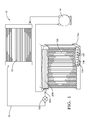
- Fig. 1 is a non-limiting example of an air conditioning system 10 having a closed refrigerant loop 12 hydraulically connecting a compressor 14, a condenser 16, and a two-pass evaporator 100 in series.
- the two-pass evaporator 100 includes a hybrid expansion device, hereafter the HED 200, configured to provide uniform refrigerant aliquoting through the two-pass evaporator 100 for all operating refrigerant flow velocities caused by variations in the compressor 14 speed.
- the HED 200 includes a first pressure-drop device such as a Low-Pressure Thermostatic Expansion Valve, hereafter the LP-TXV 202, and a second pressure-drop device such as an Enhanced Orifice Tube, hereafter the EOT 204.
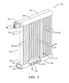
- Figs. 2 and 3 illustrate further details of the two-pass evaporator 100.
- the two-pass evaporator 100 includes an inlet manifold 102, an outlet manifold 104, and plurality of tubes 106 hydraulically connecting the inlet manifold 102 to the outlet manifold 104 for refrigerant flow therebetween.
- the tubes 106 together with a transition manifold 105 to define a U-shaped path for refrigerant flow from the inlet manifold 102 to the outlet manifold 104, thereby enabling the inlet manifold 102 and outlet manifold 104 to be placed in a side-by-side parallel arrangement.
- the inlet open ends 107 of the tubes 106 are inserted through slots 109 positioned along the inlet manifold 102 for refrigerant flow from the inlet manifold 102 to the tubes 106.
- the inlet manifold 102 and outlet manifold 104 are shown above the tubes 106 with respect to the direction of gravity.
- a plurality of fins 108 is disposed between and materially joined to the tubes 106 to facilitate heat exchange between the refrigerant and a stream of ambient air.
- the tubes 106 and fins 108 are formed of a heat conductive material, preferably an aluminum alloy, assembled onto the inlet manifold 102, the transition manifold 105, and the outlet manifold 104 and brazed together to form the two-pass evaporator heat exchanger assembly.
- FIG. 3 Shown in Fig. 3 is a cross-sectional view of the inlet manifold 102 of the two-pass evaporator 100 extending along a manifold axis A.
- the inlet manifold 102 includes an inlet port 110 for receiving the EOT 204, which is configured to cooperate with the LP-TXV 202 to improve refrigerant aliquoting across tubes 106 of the two-pass evaporator 100.
- the LP-TXV 202 expands a liquid refrigerant from the condenser into a first mixture of two-phase refrigerant and the EOT 204 expands the first mixture into a second mixture of two-phase refrigerant.
- the EOT 204 may be disposed within the chamber defined by the inlet manifold 102, extending substantially along the length of the chamber and substantially parallel with the manifold axis A.
- the EOT 204 includes an inlet end 214, a distal end 216 that may be a blind end opposite that of the inlet end 214, and a plurality of orifices 206 therebetween.
- the inlet end 214 is in direct hydraulic connection with the LP-TXV 202.
- the distal end 216 is typically mounted by capturing it in the end cap 117 of the inlet manifold 102.
- the plurality of orifices 206 may be arranged in a linear array parallel to the manifold axis A and oriented away from the inlet open ends 107 of the tubes 106, preferably 180 degrees from the inlet open ends 107 and substantially in the opposite direction of gravity.
- the in-vehicle position is such that the inlet manifold 102 and the outlet manifold 104 are at the top, the transition manifold 105 is at the bottom, and the evaporator face 112 is substantially perpendicular to the ground.
- the orifices 206 of the EOT 204 are substantially opposite to the gravity direction.
- the HED 200 provides a two stage pressure drop, in which the total pressure drop is apportioned between the LP-TXV 202 and the EOT 204 and is equivalent to the pressure drop of a conventional TXV. It was surprisingly found that a controlled two stage pressure drop provided by the LP-TXV and EOT working in unison, resulted in the improved aliquoting of refrigerant through the tubes 106 of the two-pass evaporator 100.
- the LP-TXV 202 is configured to provide a first mixture of two-phase refrigerant to the EOT 204.
- the EOT 204 serves as a retention and expansion device where it retains and accumulates the first mixture of two-phase refrigerant until the liquid part of the incoming mixture substantially fills the interior volume of the EOT 204 before being discharged through the orifices 206 as a second mixture of two-phase refrigerant, thereby aliquoting the refrigerant across the tubes 106.
- the two-pass evaporator 100 which is suitable for use in an automobile, includes an inlet manifold 102.
- the inlet manifold is configured to define the chamber for containing refrigerant, define the inlet port 110 for receiving refrigerant into the chamber, and hydraulically couple the inlet manifold 110 to a first end 120 of a first plurality of tubes 122.
- the transition manifold 105 is configured to hydraulically couple a second end 124 of the first plurality of tubes 122 to a first end 126 of a second plurality of tubes 128 arranged parallel to the first plurality of tubes 122.
- outlet manifold 104 to be located proximate to the inlet manifold 102.
- the outlet manifold defines an outlet port 132 and hydraulically couples a second end 130 of the second plurality of tubes 128 to the outlet port 132.
- the two-pass evaporator 100 includes a first pressure-drop device (LP-TXV 202) located proximate to the inlet port 110.
- the first pressure-drop device is configured to receive and expand a liquid phase refrigerant into a first mixture of two-phase refrigerant.
- the two-pass evaporator 100 also includes a second pressure-drop device (EOT 204) located within the inlet manifold 102.
- the second pressure-drop device is configured to receive and expand the first mixture of two-phase refrigerant into a second mixture of two-phase refrigerant and aliquot the second mixture of two-phase refrigerant to the first end 120 of the first plurality of tubes 122.
- the first pressure-drop device and the second pressure-drop device cooperate to form a hybrid expansion device (HED 200).
- HED 200 hybrid expansion device
- the flow-modulation plate 134 is disposed generally within the transition manifold, and is configured to segregate a transition cavity 136 defined by the transition manifold 105 into an upstream portion 138 and a downstream portion 140.
- the flow-modulation plate 134 includes or defines a plurality of openings 142 configured to aliquot refrigerant from the first plurality of tubes to the second plurality of tubes.
- the flow-modulation plate 134 provides flow restriction that better aliquots refrigerant flowing from the first plurality of tubes 122 to the second plurality of tubes 128.
- the flow-modulation plate 134 creates a back pressure on the refrigerant from the first plurality of tubes 122 by restricting the flow (i.e. - choking the flow) of refrigerant as refrigerant moves from an upstream portion 138 to a downstream portion 140. This causes better distribution of refrigerant in both the first plurality of tubes 122 to the second plurality of tubes 128.
- This advantage of the flow modulation plate further enhances the aliquoting functionality of the HED 200.
- HED 200 performs its intended function by aliquoting the two-phase refrigerant into the first plurality of tubes 122, the benefit realized by including the flow-modulation plate 134 may be less evident and the size of the opening 142 in the flow-modulation plate 134 can be larger to offer less flow restriction.
- the HED 200 may not be able to satisfactorily perform its aliquoting function.
- an undesirable refrigerant hiss or whistle noise may be generated.
- the noise is generated by refrigerant turning from liquid to vapor as the refrigerant emanates at high velocity from the orifices 206 in the EOT 204 of the HED 200.
- the HED 200 cannot deliver good flow distribution due to some design constraint such as a noise limit, then the benefit of the flow-modulation plate 134 may be more useful.
- the flow-modulation plate 134 may have smaller sized openings 142 and thus may offer higher flow resistance to the refrigerant, thereby compensating for what HED 200 could not achieve.
- the HED 200 functions cooperatively with the flow-modulation plate 134 to deliver good overall refrigerant aliquoting with minimal refrigerant noise and across a wider range of refrigerant flows. Together, the HED 200 and flow modulation plate 134 forms the hybrid flow modulation system (HFMS).
- HFMS hybrid flow modulation system
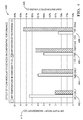
- Fig. 4 is a graph 400 of test data showing performance of an evaporator comparable to the two-pass evaporator 100 described herein when equipped with only the HED 200 (HED only 402), that is without the flow modulation plate 134 (labeled FMD in Fig. 4 ); equipped with only the flow modulation plate 134 (FMD only 404), that is without the HED 200; the expected performance characteristics for a two-pass evaporator equipped with both the HED 200 and the flow modulation plate 134 (HED+FMD_Expected 406); and the actual performance characteristics for the two-pass evaporator 100 equipped with both the HED 200 and the flow modulation plate 134 (HED+FMD_Actual 408).
- the performance characteristics include an Air Temperature Inhomogeneity 410 and an Evaporator Effectiveness 420.
- the Air Temperature Inhomogeneity 410 is determined by calculating the difference between the maximum outlet air temperature and the minimum outlet air temperature across the face of the two-pass evaporator.
- the Evaporator Effectiveness 420 is calculated based on a ratio of the heat transfer performance achieved by a given heat exchanger to the maximum heat transfer performance theoretically possible, which in this instance is when outlet air temperature is equal to the temperature of the refrigerant flowing through the pass through which air is coming out.
- the Air Temperature Inhomogeneity 410 for the HED+FMD_Expected 406 and the Evaporator Effectiveness 420 for the HED+FMD_Expected 406 are estimated based on the trend of data from tests with various evaporators with different aliquoting devices and also data from tests with different state-of-the-art evaporators used in the industry. As can be seen, the actual performance characteristics (the HED+FMD_Actual 408) for the two-pass evaporator 100 described herein is surprisingly better than the expected result.
- a two-pass evaporator 100 is provided.
- the two-pass evaporator 100 includes several features that help to aliquot refrigerant to the tubes 106 so that the temperature across the two-pass evaporator 100 is more uniform.
Landscapes
- Engineering & Computer Science (AREA)
- Physics & Mathematics (AREA)
- Mechanical Engineering (AREA)
- Thermal Sciences (AREA)
- General Engineering & Computer Science (AREA)
- Air-Conditioning For Vehicles (AREA)
- Details Of Heat-Exchange And Heat-Transfer (AREA)
Applications Claiming Priority (1)
| Application Number | Priority Date | Filing Date | Title |
|---|---|---|---|
| US14/469,000 US20160061497A1 (en) | 2013-11-01 | 2014-08-26 | Two-pass evaporator |
Publications (1)
| Publication Number | Publication Date |
|---|---|
| EP2990752A1 true EP2990752A1 (de) | 2016-03-02 |
Family
ID=53886907
Family Applications (1)
| Application Number | Title | Priority Date | Filing Date |
|---|---|---|---|
| EP15180761.7A Withdrawn EP2990752A1 (de) | 2014-08-26 | 2015-08-12 | Zweiflutiger verdampfer |
Country Status (4)
| Country | Link |
|---|---|
| US (1) | US20160061497A1 (de) |
| EP (1) | EP2990752A1 (de) |
| KR (1) | KR20160024800A (de) |
| CN (2) | CN111486621A (de) |
Cited By (4)
| Publication number | Priority date | Publication date | Assignee | Title |
|---|---|---|---|---|
| JP2018066531A (ja) * | 2016-10-21 | 2018-04-26 | パナソニックIpマネジメント株式会社 | 熱交換器およびそれを用いた冷凍システム |
| WO2018100298A1 (fr) * | 2016-11-30 | 2018-06-07 | Valeo Systemes Thermiques | Echangeur de chaleur constitutif d'un circuit de fluide réfrigérant |
| EP3423764A4 (de) * | 2016-03-04 | 2020-02-26 | Modine Manufacturing Company | Heiz- und kühlsystem und wärmetauscher dafür |
| DE102018222815A1 (de) | 2018-12-21 | 2020-06-25 | Mahle International Gmbh | Aufnahmekasten für eine Wärmeübertrager |
Families Citing this family (7)
| Publication number | Priority date | Publication date | Assignee | Title |
|---|---|---|---|---|
| US10197312B2 (en) * | 2014-08-26 | 2019-02-05 | Mahle International Gmbh | Heat exchanger with reduced length distributor tube |
| US10072900B2 (en) * | 2014-09-16 | 2018-09-11 | Mahle International Gmbh | Heat exchanger distributor with intersecting streams |
| JP2017223399A (ja) * | 2016-06-14 | 2017-12-21 | 株式会社デンソー | 冷却システム |
| US10563895B2 (en) | 2016-12-07 | 2020-02-18 | Johnson Controls Technology Company | Adjustable inlet header for heat exchanger of an HVAC system |
| CN110486514B (zh) * | 2018-05-14 | 2021-11-02 | 中国石油化工股份有限公司 | 一种流量控制装置 |
| US20200158388A1 (en) * | 2018-11-16 | 2020-05-21 | Mahle International Gmbh | Evaporator unit |
| JP7142806B1 (ja) * | 2021-10-15 | 2022-09-27 | 三菱電機株式会社 | 分配器、熱交換器およびヒートポンプ装置 |
Citations (7)
| Publication number | Priority date | Publication date | Assignee | Title |
|---|---|---|---|---|
| US5806586A (en) * | 1993-07-03 | 1998-09-15 | Ernst Flitsch Gmbh & Co. | Plate heat exchanger with a refrigerant distributor |
| EP1548380A2 (de) * | 2003-12-22 | 2005-06-29 | Hussmann Corporation | Flachrohrverdampfer mit Mikroverteiler |
| US20060162918A1 (en) * | 2001-06-18 | 2006-07-27 | Showa Denko K.K. | Evaporator, manufacturing method of the same, header for evaporator and refrigeration system |
| US20080093051A1 (en) * | 2005-02-02 | 2008-04-24 | Arturo Rios | Tube Insert and Bi-Flow Arrangement for a Header of a Heat Pump |
| US20090173483A1 (en) * | 2008-01-09 | 2009-07-09 | Delphi Technologies, Inc. | Non-cylindrical refrigerant conduit and method of making same |
| US20100089095A1 (en) * | 2006-10-13 | 2010-04-15 | Carrier Corporation | Multi-pass heat exchangers having return manifolds with distributing inserts |
| EP2869018A1 (de) * | 2013-11-01 | 2015-05-06 | Delphi Technologies, Inc. | Verdampfer mit einer hybriden Expansionsvorrichtung für verbessertes Aufteilen von Kältemittel |
Family Cites Families (28)
| Publication number | Priority date | Publication date | Assignee | Title |
|---|---|---|---|---|
| DE19719252C2 (de) * | 1997-05-07 | 2002-10-31 | Valeo Klimatech Gmbh & Co Kg | Zweiflutiger und in Luftrichtung einreihiger hartverlöteter Flachrohrverdampfer für eine Kraftfahrzeugklimaanlage |
| US6729386B1 (en) * | 2001-01-22 | 2004-05-04 | Stanley H. Sather | Pulp drier coil with improved header |
| JP3960233B2 (ja) * | 2002-04-03 | 2007-08-15 | 株式会社デンソー | 熱交換器 |
| US6814136B2 (en) * | 2002-08-06 | 2004-11-09 | Visteon Global Technologies, Inc. | Perforated tube flow distributor |
| US7886811B2 (en) * | 2003-11-14 | 2011-02-15 | Showa Denko K.K. | Evaporator and process for fabricating same |
| JP4667077B2 (ja) * | 2004-03-09 | 2011-04-06 | 昭和電工株式会社 | ジョイントプレート半製品、ジョイントプレート、ジョイントプレートの製造方法および熱交換器 |
| US7726387B2 (en) * | 2004-05-11 | 2010-06-01 | Showa Denko K.K. | Heat exchangers |
| DE112006000179T5 (de) * | 2005-01-18 | 2007-12-06 | Showa Denko K.K. | Wärmetauscher |
| EP1856588A4 (de) * | 2005-02-02 | 2010-07-21 | Carrier Corp | Parallelfluss-wärmetauscher für wärmepumpenanwendungen |
| US8171987B2 (en) * | 2006-11-13 | 2012-05-08 | Carrier Corporation | Minichannel heat exchanger header insert for distribution |
| US8607852B2 (en) * | 2007-11-14 | 2013-12-17 | Swep International Ab | Distribution pipe |
| US20090173482A1 (en) * | 2008-01-09 | 2009-07-09 | Beamer Henry E | Distributor tube subassembly |
| WO2009105454A2 (en) * | 2008-02-22 | 2009-08-27 | Liebert Corporation | Laminated sheet manifold for microchannel heat exchanger |
| US20090229805A1 (en) * | 2008-03-13 | 2009-09-17 | Delphi Technologies, Inc. | Manifold design having an improved collector conduit and method of making same |
| CN102027308A (zh) * | 2008-05-16 | 2011-04-20 | 开利公司 | 具有增强的制冷剂分布的微通道热交换器 |
| CN102099651B (zh) * | 2008-07-15 | 2013-12-25 | 开利公司 | 集成多回路微通道换热器 |
| US8234881B2 (en) * | 2008-08-28 | 2012-08-07 | Johnson Controls Technology Company | Multichannel heat exchanger with dissimilar flow |
| EP2321608A4 (de) * | 2008-09-08 | 2013-03-06 | Carrier Corp | Entwurf für ein mikrokanal-wärmetauschermodul zur reduzierung von wassereinschliessungen |
| US8439104B2 (en) * | 2009-10-16 | 2013-05-14 | Johnson Controls Technology Company | Multichannel heat exchanger with improved flow distribution |
| US8485248B2 (en) * | 2009-12-15 | 2013-07-16 | Delphi Technologies, Inc. | Flow distributor for a heat exchanger assembly |
| US20110240276A1 (en) * | 2010-04-01 | 2011-10-06 | Delphi Technologies, Inc. | Heat exchanger having an inlet distributor and outlet collector |
| JP5468982B2 (ja) * | 2010-05-14 | 2014-04-09 | カルソニックカンセイ株式会社 | 車両用空気調和装置 |
| US20110290465A1 (en) * | 2010-06-01 | 2011-12-01 | Delphi Technologies, Inc. | Orientation insensitive refrigerant distributor tube |
| US9267737B2 (en) * | 2010-06-29 | 2016-02-23 | Johnson Controls Technology Company | Multichannel heat exchangers employing flow distribution manifolds |
| CN201926209U (zh) * | 2011-01-11 | 2011-08-10 | 谭勇萍 | 双通道平行流蒸发器 |
| KR101372096B1 (ko) * | 2011-11-18 | 2014-03-07 | 엘지전자 주식회사 | 열교환기 |
| CN203771815U (zh) * | 2014-04-21 | 2014-08-13 | 南方英特空调有限公司 | 双通道平行流蒸发器 |
| US10072900B2 (en) * | 2014-09-16 | 2018-09-11 | Mahle International Gmbh | Heat exchanger distributor with intersecting streams |
-
2014
- 2014-08-26 US US14/469,000 patent/US20160061497A1/en not_active Abandoned
-
2015
- 2015-08-12 EP EP15180761.7A patent/EP2990752A1/de not_active Withdrawn
- 2015-08-18 CN CN202010220700.7A patent/CN111486621A/zh active Pending
- 2015-08-18 CN CN201510508656.9A patent/CN105387650A/zh active Pending
- 2015-08-24 KR KR1020150119006A patent/KR20160024800A/ko not_active Withdrawn
Patent Citations (7)
| Publication number | Priority date | Publication date | Assignee | Title |
|---|---|---|---|---|
| US5806586A (en) * | 1993-07-03 | 1998-09-15 | Ernst Flitsch Gmbh & Co. | Plate heat exchanger with a refrigerant distributor |
| US20060162918A1 (en) * | 2001-06-18 | 2006-07-27 | Showa Denko K.K. | Evaporator, manufacturing method of the same, header for evaporator and refrigeration system |
| EP1548380A2 (de) * | 2003-12-22 | 2005-06-29 | Hussmann Corporation | Flachrohrverdampfer mit Mikroverteiler |
| US20080093051A1 (en) * | 2005-02-02 | 2008-04-24 | Arturo Rios | Tube Insert and Bi-Flow Arrangement for a Header of a Heat Pump |
| US20100089095A1 (en) * | 2006-10-13 | 2010-04-15 | Carrier Corporation | Multi-pass heat exchangers having return manifolds with distributing inserts |
| US20090173483A1 (en) * | 2008-01-09 | 2009-07-09 | Delphi Technologies, Inc. | Non-cylindrical refrigerant conduit and method of making same |
| EP2869018A1 (de) * | 2013-11-01 | 2015-05-06 | Delphi Technologies, Inc. | Verdampfer mit einer hybriden Expansionsvorrichtung für verbessertes Aufteilen von Kältemittel |
Cited By (7)
| Publication number | Priority date | Publication date | Assignee | Title |
|---|---|---|---|---|
| EP3423764A4 (de) * | 2016-03-04 | 2020-02-26 | Modine Manufacturing Company | Heiz- und kühlsystem und wärmetauscher dafür |
| US10907865B2 (en) | 2016-03-04 | 2021-02-02 | Modine Manufacturing Company | Heating and cooling system, and heat exchanger for the same |
| JP2018066531A (ja) * | 2016-10-21 | 2018-04-26 | パナソニックIpマネジメント株式会社 | 熱交換器およびそれを用いた冷凍システム |
| WO2018100298A1 (fr) * | 2016-11-30 | 2018-06-07 | Valeo Systemes Thermiques | Echangeur de chaleur constitutif d'un circuit de fluide réfrigérant |
| FR3061284A1 (fr) * | 2016-11-30 | 2018-06-29 | Valeo Systemes Thermiques | Echangeur de chaleur constitutif d'un circuit de fluide refrigerant |
| DE102018222815A1 (de) | 2018-12-21 | 2020-06-25 | Mahle International Gmbh | Aufnahmekasten für eine Wärmeübertrager |
| US11747097B2 (en) | 2018-12-21 | 2023-09-05 | Mahle International Gmbh | Receiving box for a heat exchanger |
Also Published As
| Publication number | Publication date |
|---|---|
| CN111486621A (zh) | 2020-08-04 |
| US20160061497A1 (en) | 2016-03-03 |
| KR20160024800A (ko) | 2016-03-07 |
| CN105387650A (zh) | 2016-03-09 |
Similar Documents
| Publication | Publication Date | Title |
|---|---|---|
| EP2990752A1 (de) | Zweiflutiger verdampfer | |
| EP2869018B1 (de) | Verdampfer mit einer hybriden Expansionsvorrichtung für verbessertes Aufteilen von Kältemittel | |
| US8099978B2 (en) | Evaporator unit | |
| US9625214B2 (en) | Heat exchanger | |
| US7654108B2 (en) | Unit for refrigerant cycle device | |
| CN103282735B (zh) | 制冷剂散热器 | |
| US20080087040A1 (en) | Refrigerant cycle device with ejector | |
| JP4692295B2 (ja) | 蒸発器ユニットおよびエジェクタ式冷凍サイクル | |
| CN102016484A (zh) | 包括多流体回路的微通道热交换器 | |
| EP2629032A2 (de) | Einheitliche Wärmepumpenklimaanlage mit Wärmetauscher mit integriertem Akkumulator | |
| CN105910351B (zh) | 换热器及空调器 | |
| JP2007192504A (ja) | エジェクタ式冷凍サイクル用ユニットおよびその製造方法 | |
| US10302341B2 (en) | Ejector-integrated heat exchanger | |
| US20130333402A1 (en) | Climate control systems for motor vehicles and methods of operating the same | |
| EP2687803A2 (de) | Wärmetauschereinheit | |
| US8769984B2 (en) | Decompression device | |
| US20180126823A1 (en) | Heat exchanger and radiator-condenser unit | |
| WO2016125437A1 (ja) | エジェクタ一体型熱交換器 | |
| JP2016050761A (ja) | エジェクタ式冷凍サイクル | |
| JP6459807B2 (ja) | エジェクタ式冷凍サイクル | |
| CN100580344C (zh) | 用于喷射器型制冷循环的单元 | |
| CN112313458A (zh) | 用于加热、空气调节和制冷系统的液体接收器 | |
| US20050006072A1 (en) | Heat exchanger | |
| JP5017925B2 (ja) | エジェクタ、蒸発器ユニットおよびエジェクタ式冷凍サイクル | |
| US10890386B2 (en) | Evaporator unit including distributor tube and method thereof |
Legal Events
| Date | Code | Title | Description |
|---|---|---|---|
| PUAI | Public reference made under article 153(3) epc to a published international application that has entered the european phase |
Free format text: ORIGINAL CODE: 0009012 |
|
| AK | Designated contracting states |
Kind code of ref document: A1 Designated state(s): AL AT BE BG CH CY CZ DE DK EE ES FI FR GB GR HR HU IE IS IT LI LT LU LV MC MK MT NL NO PL PT RO RS SE SI SK SM TR |
|
| AX | Request for extension of the european patent |
Extension state: BA ME |
|
| 17P | Request for examination filed |
Effective date: 20160818 |
|
| RBV | Designated contracting states (corrected) |
Designated state(s): AL AT BE BG CH CY CZ DE DK EE ES FI FR GB GR HR HU IE IS IT LI LT LU LV MC MK MT NL NO PL PT RO RS SE SI SK SM TR |
|
| RAP1 | Party data changed (applicant data changed or rights of an application transferred) |
Owner name: MAHLE INTERNATIONAL GMBH |
|
| STAA | Information on the status of an ep patent application or granted ep patent |
Free format text: STATUS: EXAMINATION IS IN PROGRESS |
|
| 17Q | First examination report despatched |
Effective date: 20200507 |
|
| STAA | Information on the status of an ep patent application or granted ep patent |
Free format text: STATUS: THE APPLICATION IS DEEMED TO BE WITHDRAWN |
|
| 18D | Application deemed to be withdrawn |
Effective date: 20210330 |