EP1548788A2 - Système d'électrode pour une lampe à décharge, lampe a décharge le comprenant et procédé se son fabrication - Google Patents
Système d'électrode pour une lampe à décharge, lampe a décharge le comprenant et procédé se son fabrication Download PDFInfo
- Publication number
- EP1548788A2 EP1548788A2 EP04028991A EP04028991A EP1548788A2 EP 1548788 A2 EP1548788 A2 EP 1548788A2 EP 04028991 A EP04028991 A EP 04028991A EP 04028991 A EP04028991 A EP 04028991A EP 1548788 A2 EP1548788 A2 EP 1548788A2
- Authority
- EP
- European Patent Office
- Prior art keywords
- electrode
- metal foil
- power supply
- supply wire
- electrode system
- Prior art date
- Legal status (The legal status is an assumption and is not a legal conclusion. Google has not performed a legal analysis and makes no representation as to the accuracy of the status listed.)
- Granted
Links
- 238000004519 manufacturing process Methods 0.000 title claims abstract description 6
- 239000011888 foil Substances 0.000 claims abstract description 88
- 229910052751 metal Inorganic materials 0.000 claims abstract description 51
- 239000002184 metal Substances 0.000 claims abstract description 51
- 238000000034 method Methods 0.000 claims description 15
- 238000003466 welding Methods 0.000 claims description 13
- 238000005304 joining Methods 0.000 claims description 2
- 238000007789 sealing Methods 0.000 abstract description 3
- 229910052750 molybdenum Inorganic materials 0.000 description 47
- 239000011733 molybdenum Substances 0.000 description 47
- ZOKXTWBITQBERF-UHFFFAOYSA-N Molybdenum Chemical compound [Mo] ZOKXTWBITQBERF-UHFFFAOYSA-N 0.000 description 45
- VYPSYNLAJGMNEJ-UHFFFAOYSA-N Silicium dioxide Chemical compound O=[Si]=O VYPSYNLAJGMNEJ-UHFFFAOYSA-N 0.000 description 8
- 239000011521 glass Substances 0.000 description 6
- 239000002019 doping agent Substances 0.000 description 4
- MRELNEQAGSRDBK-UHFFFAOYSA-N lanthanum(3+);oxygen(2-) Chemical compound [O-2].[O-2].[O-2].[La+3].[La+3] MRELNEQAGSRDBK-UHFFFAOYSA-N 0.000 description 4
- 229910001507 metal halide Inorganic materials 0.000 description 4
- 150000005309 metal halides Chemical class 0.000 description 4
- 238000005336 cracking Methods 0.000 description 3
- 230000008569 process Effects 0.000 description 3
- FVAUCKIRQBBSSJ-UHFFFAOYSA-M sodium iodide Chemical compound [Na+].[I-] FVAUCKIRQBBSSJ-UHFFFAOYSA-M 0.000 description 3
- WFKWXMTUELFFGS-UHFFFAOYSA-N tungsten Chemical compound [W] WFKWXMTUELFFGS-UHFFFAOYSA-N 0.000 description 3
- 229910052721 tungsten Inorganic materials 0.000 description 3
- 239000010937 tungsten Substances 0.000 description 3
- 229910001182 Mo alloy Inorganic materials 0.000 description 2
- ZLMJMSJWJFRBEC-UHFFFAOYSA-N Potassium Chemical compound [K] ZLMJMSJWJFRBEC-UHFFFAOYSA-N 0.000 description 2
- 238000000576 coating method Methods 0.000 description 2
- 238000010438 heat treatment Methods 0.000 description 2
- QSHDDOUJBYECFT-UHFFFAOYSA-N mercury Chemical compound [Hg] QSHDDOUJBYECFT-UHFFFAOYSA-N 0.000 description 2
- 229910052753 mercury Inorganic materials 0.000 description 2
- 150000002751 molybdenum Chemical class 0.000 description 2
- 229910052700 potassium Inorganic materials 0.000 description 2
- 239000011591 potassium Substances 0.000 description 2
- 230000009467 reduction Effects 0.000 description 2
- 238000005096 rolling process Methods 0.000 description 2
- 229910052710 silicon Inorganic materials 0.000 description 2
- 239000010703 silicon Substances 0.000 description 2
- RUDFQVOCFDJEEF-UHFFFAOYSA-N yttrium(III) oxide Inorganic materials [O-2].[O-2].[O-2].[Y+3].[Y+3] RUDFQVOCFDJEEF-UHFFFAOYSA-N 0.000 description 2
- VYZAMTAEIAYCRO-UHFFFAOYSA-N Chromium Chemical compound [Cr] VYZAMTAEIAYCRO-UHFFFAOYSA-N 0.000 description 1
- KJTLSVCANCCWHF-UHFFFAOYSA-N Ruthenium Chemical compound [Ru] KJTLSVCANCCWHF-UHFFFAOYSA-N 0.000 description 1
- 229910001080 W alloy Inorganic materials 0.000 description 1
- 230000002146 bilateral effect Effects 0.000 description 1
- 239000000919 ceramic Substances 0.000 description 1
- 230000008859 change Effects 0.000 description 1
- 239000011248 coating agent Substances 0.000 description 1
- 238000005260 corrosion Methods 0.000 description 1
- 230000007797 corrosion Effects 0.000 description 1
- 230000007423 decrease Effects 0.000 description 1
- 230000003247 decreasing effect Effects 0.000 description 1
- 230000001419 dependent effect Effects 0.000 description 1
- 239000007789 gas Substances 0.000 description 1
- 239000011261 inert gas Substances 0.000 description 1
- 238000009413 insulation Methods 0.000 description 1
- 150000004694 iodide salts Chemical class 0.000 description 1
- 239000000155 melt Substances 0.000 description 1
- 229910052707 ruthenium Inorganic materials 0.000 description 1
- HUIHCQPFSRNMNM-UHFFFAOYSA-K scandium(3+);triiodide Chemical compound [Sc+3].[I-].[I-].[I-] HUIHCQPFSRNMNM-UHFFFAOYSA-K 0.000 description 1
- 239000000377 silicon dioxide Substances 0.000 description 1
- 235000009518 sodium iodide Nutrition 0.000 description 1
- ZCUFMDLYAMJYST-UHFFFAOYSA-N thorium dioxide Chemical compound O=[Th]=O ZCUFMDLYAMJYST-UHFFFAOYSA-N 0.000 description 1
- 229910003452 thorium oxide Inorganic materials 0.000 description 1
- 230000007704 transition Effects 0.000 description 1
- 229910052724 xenon Inorganic materials 0.000 description 1
- FHNFHKCVQCLJFQ-UHFFFAOYSA-N xenon atom Chemical compound [Xe] FHNFHKCVQCLJFQ-UHFFFAOYSA-N 0.000 description 1
Images



Classifications
-
- H—ELECTRICITY
- H01—ELECTRIC ELEMENTS
- H01J—ELECTRIC DISCHARGE TUBES OR DISCHARGE LAMPS
- H01J5/00—Details relating to vessels or to leading-in conductors common to two or more basic types of discharge tubes or lamps
- H01J5/32—Seals for leading-in conductors
- H01J5/38—Pinched-stem or analogous seals
-
- H—ELECTRICITY
- H01—ELECTRIC ELEMENTS
- H01J—ELECTRIC DISCHARGE TUBES OR DISCHARGE LAMPS
- H01J61/00—Gas-discharge or vapour-discharge lamps
- H01J61/02—Details
- H01J61/36—Seals between parts of vessels; Seals for leading-in conductors; Leading-in conductors
-
- H—ELECTRICITY
- H01—ELECTRIC ELEMENTS
- H01J—ELECTRIC DISCHARGE TUBES OR DISCHARGE LAMPS
- H01J9/00—Apparatus or processes specially adapted for the manufacture, installation, removal, maintenance of electric discharge tubes, discharge lamps, or parts thereof; Recovery of material from discharge tubes or lamps
- H01J9/24—Manufacture or joining of vessels, leading-in conductors or bases
- H01J9/28—Manufacture of leading-in conductors
-
- H—ELECTRICITY
- H01—ELECTRIC ELEMENTS
- H01J—ELECTRIC DISCHARGE TUBES OR DISCHARGE LAMPS
- H01J9/00—Apparatus or processes specially adapted for the manufacture, installation, removal, maintenance of electric discharge tubes, discharge lamps, or parts thereof; Recovery of material from discharge tubes or lamps
- H01J9/24—Manufacture or joining of vessels, leading-in conductors or bases
- H01J9/32—Sealing leading-in conductors
- H01J9/323—Sealing leading-in conductors into a discharge lamp or a gas-filled discharge device
- H01J9/326—Sealing leading-in conductors into a discharge lamp or a gas-filled discharge device making pinched-stem or analogous seals
-
- H—ELECTRICITY
- H01—ELECTRIC ELEMENTS
- H01K—ELECTRIC INCANDESCENT LAMPS
- H01K1/00—Details
- H01K1/38—Seals for leading-in conductors
-
- H—ELECTRICITY
- H01—ELECTRIC ELEMENTS
- H01K—ELECTRIC INCANDESCENT LAMPS
- H01K1/00—Details
- H01K1/40—Leading-in conductors
Definitions
- the invention relates to an electrode system for a discharge lamp according to Preamble of claim 1 and a discharge lamp with such Electrode system and a method for producing such an electrode system.
- Such an electrode system is for example in the European patent application EP 0 884 763 A2.
- This document describes an electrode system with a molybdenum foil fuse in quartz glass, wherein a first end of the embedded in quartz glass molybdenum foil with an electrode and a second end this molybdenum foil is connected to a power supply wire. That with the Electrode connected first end of the molybdenum foil is wedge-shaped, the means it has a reduced thickness, the risk of cracking in the glass due to the different thermal expansion coefficients of quartz glass and reduce molybdenum.
- the electrode system according to the invention has one for generating a gas discharge serving electrode and at least one metal foil, the first end with the electrode is connected and the second end with a Stromzufihrungsdraht, which serves to supply power to the electrode is connected.
- the at least one metal foil on at least one of its aforementioned Ends, but preferably at both ends, a reduced width.
- the width of the at least one metal foil in the direction their first or second end steadily reduced.
- both the electrode and the power supply wire have one flattened portion associated with the first and second ends of the at least one Metal foil is welded.
- Tensions in the sealing area of the discharge vessel are the flattened ones Ends of the electrode and the power supply wire advantageously rounded educated.
- the edge of the flattened portion of the electrode or the power supply wire in an advantageous manner with a Bevel provided a reduction in the thickness of the flattened portion of his Edge causes and thus also to reduce mechanical stresses in contributes to the sealing region of the discharge vessel.
- the minimum width of the at least one narrowed end of at least a metal foil preferably less than or equal to or width of the with this End connected, flattened portion of the electrode or the Power supply wire.
- the electrode system according to the invention is advantageously used for discharge lamps, used in particular for high pressure discharge lamps.
- the discharge lamp according to the invention has a discharge vessel, which with a Discharge space and at least one sealed, with an inventive Equipped with electrode system end, with the free end the electrode protrudes into the discharge space, the at least one metal foil embedded in a gastight manner in the at least one sealed end of the discharge vessel is and the free end of the power supply wire from the sealed end led out of the discharge vessel.
- the non-flattened portion of the electrode is advantageously arranged completely in the discharge space, while the flattened portion of the electrode is preferably partially or completely extends into the sealed end of the discharge vessel. This will be also the mechanical stresses in the sealed end of the discharge vessel decreases during lamp operation and also serves the transition area from the flattened to the non-flattened portion of the electrode as a stop for the adjustment or alignment of the electrode in the discharge vessel.
- the electrode system according to the invention is preferably used in discharge lamps used, which have a discharge vessel made of quartz glass, that is, the glass contains at least 95 weight percent silica.
- Such discharge vessels Withstand very high operating temperatures and are therefore commonly used for High-pressure discharge lamps, such as metal halide high pressure discharge lamps used.
- the electrodes of such a discharge lamp are made preferably of tungsten containing dopants - for example, thorium oxide can, or from a tungsten alloy.
- Your power supply wires exist preferably of molybdenum, the dopants - for example, potassium and silicon, or yttria or lanthanum oxide - or of a molybdenum alloy.
- the at least one metal foil of the electrode system according to the invention in this discharge lamp type is preferably made of a molybdenum foil
- the Dopants - for example, potassium and silicon, or yttria or lanthanum oxide - may contain, or of a molybdenum alloy.
- the aforementioned molybdenum foil can be unilateral or bilateral with a coating - for example Chrome or ruthenium - be provided to protect it from corrosion. These Coatings may additionally occur on the flattened portion of the electrode or the power supply wire.
- the process for producing the electrode system according to the invention provides in that before joining the at least one metal foil to the electrode and the Power supply wire at least one end of the at least one metal foil such is tailored so that the at least one metal foil at this end reduces one Has width.
- the to be connected with this metal foil Section of the electrode and / or the power supply wire is before Bonding with the metal foil flattened, for example by cold forming by means Rolling or hammering.
- the free Ends of these sections are rounded off by heating to a dome, for example by heating by means of a laser or by TIG welding (tungsten inert gas welding) or by means of a plasma welding process.
- TIG welding tungsten inert gas welding
- the edge of the flattened Section of the electrode and / or the Stromzufihrungsstrahtes is due the advantages already mentioned above preferably provided with a chamfer, for example is produced by rolling.
- the connection between the at least a metal foil and the flattened portion of the electrode and / or the Power supply wire is easily by welding, preferably produced by spot welding. This weld can be easily Produce way by means of a laser.
- FIG. 1 shows a schematic representation of the preferred embodiment of the electrode system according to the invention, preferably in a metal halide high-pressure discharge lamp used for a vehicle headlight becomes.
- the electrode system has a molybdenum foil 10 with longitudinal edges 11 and 12, the a tapered first end 101 defined by the sloping side edges 13, 14 is limited, and a tapered second end 102, by the oblique Side edges 15, 16 is limited have.
- the cross section of this molybdenum foil 10 is lenticular. That is, their thickness, starting from their centerline in the direction of its two side edges 11, 12 towards, steadily decreasing. The thickness in the film center is less than 150 microns, preferably about 25 microns. It depends on the required current carrying capacity of the molybdenum foil 10 from.
- the width of the molybdenum foil 10, that is, the distance between the longitudinal edges 11 and 12 is 2 mm.
- the minimum width of the molybdenum foil 10 at its tapered ends 101 and 102 is at least 0.2 mm and is at most as wide as the width of the flattened Ends 21, 31 of the electrode and the power supply wire.
- the first end 101 of the molybdenum foil 10 is made with a rod-shaped electrode 20 Tungsten connected.
- This electrode 20 has a flattened end 21, the by two welding points 41, which were produced by means of a laser, with the tapered first end 101 of the molybdenum foil 10 is welded.
- the electrode 20 has a diameter of about 0.25 mm in the non-flattened area 20.
- the flattened portion 21 of the electrode 20 has a thickness of about 100 microns and a width of about 0.8 mm.
- the second end 102 of the molybdenum foil 10 is connected to a Stromzufihrungsdraht 30th made of molybdenum.
- This power supply wire 30 has a flattened At the end of 31, this was done by two welding spots 42, made by means of a laser were welded to the tapered second end 102 of the molybdenum foil 10.
- the Stromzufihrungsdraht 30 has a non-flattened area 30 a Diameter of about 0.4 mm.
- the free end of the flattened portion 21 of the electrode 20 is as in the figures 2 and 3a shown schematically rounded. The same is true for the free end of the flattened portion 31 of the power supply wire 30th
- the edge of the flattened portion 21 of the electrode 20 is as shown in Figs. 3a and 3b schematically illustrated, provided with a chamfer 22 or bevel, the an angle or inclination of 45 degrees to that with the molybdenum foil 10 welded top of the section 21 has.
- FIG. 4a shows a molybdenum ribbon from which the molybdenum foil 10 is cut off a correspondingly long piece is won.
- the sloping Side edges 13, 14 and 15, 16 are thereby punched out of a V-shaped Section of two adjacent molybdenum foils 10 produced. Subsequently The adjacent molybdenum foils 10 are cut apart.
- the Cut edges of the molybdenum foils 10 can be rolled as in the published patent application EP 0 884 763 A2. In the molybdenum foil 10, the tapered Ends 101 and 102 formed symmetrically.
- Molybdenum foils 10 ' form the oblique side edges 13', 14 'and 15 ', 16' different angles with the longitudinal edges of the molybdenum foil 10 '. Accordingly their tapered ends are formed asymmetrically.
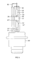
- FIG 5 is a metal halide high-pressure discharge lamp for a Motor vehicle headlight shown schematically.
- This lamp has a discharge vessel 50 made of quartz glass with a discharge space 51 and two diametrically arranged, sealed ends 52, each an electrode system according to the invention with an electrode 20 or 20 ", a molybdenum foil 10 or 10" and a In the discharge space of the discharge vessel, into which the free ends of the electrodes 20, 20 "protrude is one ionizable filling gas-tight enclosed, the xenon and metal halides, for example Sodium iodide, scandium iodide and possibly other iodides, as well as mercury contains. However, the mercury can also be dispensed with.
- the discharge vessel 50 is surrounded by an outer bulb 70 made of quartz glass, the ultraviolet radiation-absorbing dopants is provided.
- the lamp has a plastic base 80, which carries the two lamp vessels 50, 80 and the equipped with the electrical connections of the lamp.
- the remote power supply wire 30 is provided over the provided with a ceramic insulation 61 current return 60 connected to one of the electrical connections (not shown), while the sockelnahe power supply wire 30 "with the other electrical Connection (not shown) is connected.
- the non-flattened portion of the electrode 20 and 20 "completely arranged in the discharge space 51 of the discharge vessel 50, while the flattened portion 21 of the electrode 20 or 20 "in each case a sealed End 52 of the discharge vessel 50 extends.
- the molybdenum foils are 10 and 10 ", respectively embedded in a gastight manner in the respective end 52 of the discharge vessel 50.
- the inner diameter of the substantially circular cylindrical discharge space 51 2.7 mm.
- the outer contour of the discharge vessel 50 has in the region of Discharge space 51 the shape of a rotationally symmetric ellipsoid.
- the invention is not limited to the above-described preferred embodiment the invention.
- the ends of the molybdenum foils 10 or 10 "instead of wedge-shaped narrowed formed in another way tapered be.
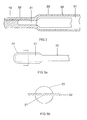
- the aforementioned ends of the molybdenum foils could be narrowed by their edges are arched or formed with curves be provided, as shown for example in the one shown in Figure 6 second embodiment of the invention is shown.
- the with the electrode or the Stromzufihrungsdraht to be joined ends of the molybdenum foil 10 "' are each bounded by a curved edge 101 "', 102'".
- the vaulting of this Edges 101 "', 102"' may correspond, for example, to a conic segment or, as shown in Figure 6, the shape of the letter U with diverging U-legs have.
- the flattening of the molybdenum foils 10 or 10 "welded ends 21st or 31 of the electrode 20 and the power supply wire 30 is not necessarily required. It is possible the degree of flattening of the molybdenum foils 10 or 10 "welded ends 21 and 31 of the electrode 20 and the power supply wire 30 to vary. For example, the flattened ends 21 and 31 have a thickness of only 80 .mu.m instead of the above 100 .mu.m. It is but also possible on the flattening of the molybdenum foils 10 or 10 "welded Ends 21 and 31 of the electrode 20 and the power supply wire 30th to renounce.
- the laser beam is on with the molybdenum foil 10 and 10 "overlapping end 21 and 31 of the electrode 20 and the power supply wire 30 and not on the molybdenum foil 10 or 10 "to a
- To perforate the molybdenum foil 10 or 10 "to prevent the overlap area between the molybdenum foil 10 or 10 "and the aforementioned end 21 or 31 of the electrode 20 and the power supply wire 30 is in the preferred Embodiments in the longitudinal direction of the molybdenum foil 1 mm to 2 mm.
Landscapes
- Engineering & Computer Science (AREA)
- Manufacturing & Machinery (AREA)
- Vessels And Coating Films For Discharge Lamps (AREA)
- Discharge Lamp (AREA)
Applications Claiming Priority (4)
| Application Number | Priority Date | Filing Date | Title |
|---|---|---|---|
| DE10361105A DE10361105A1 (de) | 2003-12-22 | 2003-12-22 | Elektrodensystem für eine Entladungslampe, Entladungslampe mit einem derartigen Elektrodensystem und Verfahren zur Herstellung eines derartigen Elektrodensystems |
| DE10361105 | 2003-12-22 | ||
| DE4003041 | 2004-01-20 | ||
| DE200410003041 DE102004003041A1 (de) | 2004-01-20 | 2004-01-20 | Elektrodensystem für eine Entladungslampe, Entladungslampe mit einem derartigen Elektrodensystem und Verfahren zur Herstellung eines derartigen Elektrodensystems |
Publications (3)
| Publication Number | Publication Date |
|---|---|
| EP1548788A2 true EP1548788A2 (fr) | 2005-06-29 |
| EP1548788A3 EP1548788A3 (fr) | 2007-01-17 |
| EP1548788B1 EP1548788B1 (fr) | 2009-02-11 |
Family
ID=34553339
Family Applications (1)
| Application Number | Title | Priority Date | Filing Date |
|---|---|---|---|
| EP04028991A Expired - Lifetime EP1548788B1 (fr) | 2003-12-22 | 2004-12-07 | Système d'électrode pour une lampe à décharge, lampe à décharge le comprenant et procédé de sa fabrication |
Country Status (4)
| Country | Link |
|---|---|
| EP (1) | EP1548788B1 (fr) |
| JP (1) | JP2005183398A (fr) |
| AT (1) | ATE422706T1 (fr) |
| DE (1) | DE502004008963D1 (fr) |
Cited By (2)
| Publication number | Priority date | Publication date | Assignee | Title |
|---|---|---|---|---|
| WO2006099849A1 (fr) * | 2005-03-22 | 2006-09-28 | Patent-Treuhand-Gesellschaft für elektrische Glühlampen mbH | Procede de fabrication d'une electrode et lampe a decharge comportant une telle electrode |
| WO2009106133A1 (fr) * | 2008-02-27 | 2009-09-03 | Osram Gesellschaft mit beschränkter Haftung | Feuille scellée, son procédé de fabrication et lampe munie d'une telle feuille |
Families Citing this family (1)
| Publication number | Priority date | Publication date | Assignee | Title |
|---|---|---|---|---|
| JP2017216146A (ja) * | 2016-05-31 | 2017-12-07 | 東芝ライテック株式会社 | ロングアーク型紫外線ランプ及び照射装置 |
Citations (4)
| Publication number | Priority date | Publication date | Assignee | Title |
|---|---|---|---|---|
| US3868528A (en) | 1974-01-14 | 1975-02-25 | Gen Electric | Quartz pinches containing sealant glass |
| GB2002954A (en) | 1977-08-15 | 1979-02-28 | Gen Electric | Electrode in lead for miniature discharge lamps |
| GB2048563A (en) | 1979-04-23 | 1980-12-10 | Gen Electric | Discharge lamps |
| EP0884763A2 (fr) | 1997-06-11 | 1998-12-16 | Patent-Treuhand-Gesellschaft für elektrische Glühlampen mbH | Scellement d'une feuille de molybdène dans le verre et lampe électrique comportant une feuille de molybdène ainsi scellée |
-
2004
- 2004-12-07 EP EP04028991A patent/EP1548788B1/fr not_active Expired - Lifetime
- 2004-12-07 DE DE502004008963T patent/DE502004008963D1/de not_active Expired - Fee Related
- 2004-12-07 AT AT04028991T patent/ATE422706T1/de not_active IP Right Cessation
- 2004-12-21 JP JP2004370154A patent/JP2005183398A/ja not_active Withdrawn
Patent Citations (4)
| Publication number | Priority date | Publication date | Assignee | Title |
|---|---|---|---|---|
| US3868528A (en) | 1974-01-14 | 1975-02-25 | Gen Electric | Quartz pinches containing sealant glass |
| GB2002954A (en) | 1977-08-15 | 1979-02-28 | Gen Electric | Electrode in lead for miniature discharge lamps |
| GB2048563A (en) | 1979-04-23 | 1980-12-10 | Gen Electric | Discharge lamps |
| EP0884763A2 (fr) | 1997-06-11 | 1998-12-16 | Patent-Treuhand-Gesellschaft für elektrische Glühlampen mbH | Scellement d'une feuille de molybdène dans le verre et lampe électrique comportant une feuille de molybdène ainsi scellée |
Cited By (2)
| Publication number | Priority date | Publication date | Assignee | Title |
|---|---|---|---|---|
| WO2006099849A1 (fr) * | 2005-03-22 | 2006-09-28 | Patent-Treuhand-Gesellschaft für elektrische Glühlampen mbH | Procede de fabrication d'une electrode et lampe a decharge comportant une telle electrode |
| WO2009106133A1 (fr) * | 2008-02-27 | 2009-09-03 | Osram Gesellschaft mit beschränkter Haftung | Feuille scellée, son procédé de fabrication et lampe munie d'une telle feuille |
Also Published As
| Publication number | Publication date |
|---|---|
| DE502004008963D1 (de) | 2009-03-26 |
| JP2005183398A (ja) | 2005-07-07 |
| EP1548788B1 (fr) | 2009-02-11 |
| ATE422706T1 (de) | 2009-02-15 |
| EP1548788A3 (fr) | 2007-01-17 |
Similar Documents
| Publication | Publication Date | Title |
|---|---|---|
| EP0479087A1 (fr) | Lampe à décharge à haute pression | |
| DE69403176T2 (de) | Elektrische Lampe | |
| EP2020018B1 (fr) | Lampe à décharge à haute pression | |
| DE10241398B4 (de) | Verfahren zur Herstellung einer Bogenentladungsröhre für eine Entladungslampe | |
| WO2006099850A2 (fr) | Lampe comportant une alimentation electrique et une electrode | |
| EP0884763B1 (fr) | Scellement d'une feuille de molybdène dans le verre et lampe électrique comportant une feuille de molybdène ainsi scellée | |
| EP1817790B1 (fr) | Lampe a decharge haute pression | |
| EP1548788B1 (fr) | Système d'électrode pour une lampe à décharge, lampe à décharge le comprenant et procédé de sa fabrication | |
| EP2143131B1 (fr) | Procédé de fabrication d'une feuille de molybdène pour la construction de lampes | |
| EP1730766B1 (fr) | Systeme d'electrodes pour lampe a decharge gazeuse haute pression | |
| EP1652211A2 (fr) | Systeme d'electrode pourvu d'un nouveau type de liaison, lampe associee comprenant un tel systeme et procede de production de ladite liaison | |
| DE69011145T2 (de) | Einseitig gequetschte Metalldampfentladungslampe. | |
| DE102004003041A1 (de) | Elektrodensystem für eine Entladungslampe, Entladungslampe mit einem derartigen Elektrodensystem und Verfahren zur Herstellung eines derartigen Elektrodensystems | |
| EP1351278B1 (fr) | Lampe à halogénure métallique avec enveloppe céramique | |
| DE10159580B4 (de) | Bogenentladungsröhre und Verfahren zu deren Herstellung | |
| DE10361105A1 (de) | Elektrodensystem für eine Entladungslampe, Entladungslampe mit einem derartigen Elektrodensystem und Verfahren zur Herstellung eines derartigen Elektrodensystems | |
| EP0588201A2 (fr) | Lampe à décharge haute pression et procédé pour la fabrication d'une lampe à décharge à haute pression | |
| EP1465236A2 (fr) | Lampe à décharge | |
| DE102010040779A1 (de) | Verfahren zum Verschweißen von Molybdänfolie und Molybdän- oder Wolframstift | |
| DE19603301C2 (de) | Elektrische Lampe mit Molybdänfoliendurchführungen für ein Lampengefäß aus Quarzglas | |
| EP1861862B1 (fr) | Procede de fabrication d'une electrode et lampe a decharge comportant une telle electrode | |
| DE60111103T2 (de) | Hochdruckentladungslampe | |
| DE102018201068B4 (de) | Glühlampe für fahrzeugscheinwerfer und herstellungsverfahren | |
| EP1756853B1 (fr) | Electrode pour lampe a decharge et lampe a decharge ainsi obtenue | |
| EP2154706A2 (fr) | Feuille pour lampes et lampe électrique dotée d'une telle feuille ainsi que procédé de fabrication correspondant |
Legal Events
| Date | Code | Title | Description |
|---|---|---|---|
| PUAI | Public reference made under article 153(3) epc to a published international application that has entered the european phase |
Free format text: ORIGINAL CODE: 0009012 |
|
| AK | Designated contracting states |
Kind code of ref document: A2 Designated state(s): AT BE BG CH CY CZ DE DK EE ES FI FR GB GR HU IE IS IT LI LT LU MC NL PL PT RO SE SI SK TR |
|
| AX | Request for extension of the european patent |
Extension state: AL BA HR LV MK YU |
|
| PUAL | Search report despatched |
Free format text: ORIGINAL CODE: 0009013 |
|
| AK | Designated contracting states |
Kind code of ref document: A3 Designated state(s): AT BE BG CH CY CZ DE DK EE ES FI FR GB GR HU IE IS IT LI LT LU MC NL PL PT RO SE SI SK TR |
|
| AX | Request for extension of the european patent |
Extension state: AL BA HR LV MK YU |
|
| 17P | Request for examination filed |
Effective date: 20070322 |
|
| 17Q | First examination report despatched |
Effective date: 20070504 |
|
| AKX | Designation fees paid |
Designated state(s): AT BE BG CH CY CZ DE DK EE ES FI FR GB GR HU IE IS IT LI LT LU MC NL PL PT RO SE SI SK TR |
|
| GRAP | Despatch of communication of intention to grant a patent |
Free format text: ORIGINAL CODE: EPIDOSNIGR1 |
|
| GRAS | Grant fee paid |
Free format text: ORIGINAL CODE: EPIDOSNIGR3 |
|
| GRAA | (expected) grant |
Free format text: ORIGINAL CODE: 0009210 |
|
| AK | Designated contracting states |
Kind code of ref document: B1 Designated state(s): AT BE BG CH CY CZ DE DK EE ES FI FR GB GR HU IE IS IT LI LT LU MC NL PL PT RO SE SI SK TR |
|
| REG | Reference to a national code |
Ref country code: GB Ref legal event code: FG4D Free format text: NOT ENGLISH |
|
| REG | Reference to a national code |
Ref country code: CH Ref legal event code: EP |
|
| REG | Reference to a national code |
Ref country code: IE Ref legal event code: FG4D Free format text: LANGUAGE OF EP DOCUMENT: GERMAN |
|
| REF | Corresponds to: |
Ref document number: 502004008963 Country of ref document: DE Date of ref document: 20090326 Kind code of ref document: P |
|
| PG25 | Lapsed in a contracting state [announced via postgrant information from national office to epo] |
Ref country code: ES Free format text: LAPSE BECAUSE OF FAILURE TO SUBMIT A TRANSLATION OF THE DESCRIPTION OR TO PAY THE FEE WITHIN THE PRESCRIBED TIME-LIMIT Effective date: 20090522 Ref country code: SI Free format text: LAPSE BECAUSE OF FAILURE TO SUBMIT A TRANSLATION OF THE DESCRIPTION OR TO PAY THE FEE WITHIN THE PRESCRIBED TIME-LIMIT Effective date: 20090211 Ref country code: FI Free format text: LAPSE BECAUSE OF FAILURE TO SUBMIT A TRANSLATION OF THE DESCRIPTION OR TO PAY THE FEE WITHIN THE PRESCRIBED TIME-LIMIT Effective date: 20090211 Ref country code: NL Free format text: LAPSE BECAUSE OF FAILURE TO SUBMIT A TRANSLATION OF THE DESCRIPTION OR TO PAY THE FEE WITHIN THE PRESCRIBED TIME-LIMIT Effective date: 20090211 Ref country code: LT Free format text: LAPSE BECAUSE OF FAILURE TO SUBMIT A TRANSLATION OF THE DESCRIPTION OR TO PAY THE FEE WITHIN THE PRESCRIBED TIME-LIMIT Effective date: 20090211 |
|
| NLV1 | Nl: lapsed or annulled due to failure to fulfill the requirements of art. 29p and 29m of the patents act | ||
| PG25 | Lapsed in a contracting state [announced via postgrant information from national office to epo] |
Ref country code: IS Free format text: LAPSE BECAUSE OF FAILURE TO SUBMIT A TRANSLATION OF THE DESCRIPTION OR TO PAY THE FEE WITHIN THE PRESCRIBED TIME-LIMIT Effective date: 20090611 Ref country code: SE Free format text: LAPSE BECAUSE OF FAILURE TO SUBMIT A TRANSLATION OF THE DESCRIPTION OR TO PAY THE FEE WITHIN THE PRESCRIBED TIME-LIMIT Effective date: 20090511 Ref country code: PL Free format text: LAPSE BECAUSE OF FAILURE TO SUBMIT A TRANSLATION OF THE DESCRIPTION OR TO PAY THE FEE WITHIN THE PRESCRIBED TIME-LIMIT Effective date: 20090211 |
|
| REG | Reference to a national code |
Ref country code: IE Ref legal event code: FD4D |
|
| PG25 | Lapsed in a contracting state [announced via postgrant information from national office to epo] |
Ref country code: DK Free format text: LAPSE BECAUSE OF FAILURE TO SUBMIT A TRANSLATION OF THE DESCRIPTION OR TO PAY THE FEE WITHIN THE PRESCRIBED TIME-LIMIT Effective date: 20090211 Ref country code: PT Free format text: LAPSE BECAUSE OF FAILURE TO SUBMIT A TRANSLATION OF THE DESCRIPTION OR TO PAY THE FEE WITHIN THE PRESCRIBED TIME-LIMIT Effective date: 20090713 Ref country code: IE Free format text: LAPSE BECAUSE OF FAILURE TO SUBMIT A TRANSLATION OF THE DESCRIPTION OR TO PAY THE FEE WITHIN THE PRESCRIBED TIME-LIMIT Effective date: 20090211 Ref country code: EE Free format text: LAPSE BECAUSE OF FAILURE TO SUBMIT A TRANSLATION OF THE DESCRIPTION OR TO PAY THE FEE WITHIN THE PRESCRIBED TIME-LIMIT Effective date: 20090211 Ref country code: CZ Free format text: LAPSE BECAUSE OF FAILURE TO SUBMIT A TRANSLATION OF THE DESCRIPTION OR TO PAY THE FEE WITHIN THE PRESCRIBED TIME-LIMIT Effective date: 20090211 |
|
| PG25 | Lapsed in a contracting state [announced via postgrant information from national office to epo] |
Ref country code: RO Free format text: LAPSE BECAUSE OF FAILURE TO SUBMIT A TRANSLATION OF THE DESCRIPTION OR TO PAY THE FEE WITHIN THE PRESCRIBED TIME-LIMIT Effective date: 20090211 Ref country code: SK Free format text: LAPSE BECAUSE OF FAILURE TO SUBMIT A TRANSLATION OF THE DESCRIPTION OR TO PAY THE FEE WITHIN THE PRESCRIBED TIME-LIMIT Effective date: 20090211 |
|
| PLBE | No opposition filed within time limit |
Free format text: ORIGINAL CODE: 0009261 |
|
| STAA | Information on the status of an ep patent application or granted ep patent |
Free format text: STATUS: NO OPPOSITION FILED WITHIN TIME LIMIT |
|
| 26N | No opposition filed |
Effective date: 20091112 |
|
| PG25 | Lapsed in a contracting state [announced via postgrant information from national office to epo] |
Ref country code: BG Free format text: LAPSE BECAUSE OF FAILURE TO SUBMIT A TRANSLATION OF THE DESCRIPTION OR TO PAY THE FEE WITHIN THE PRESCRIBED TIME-LIMIT Effective date: 20090511 |
|
| BERE | Be: lapsed |
Owner name: PATENT-TREUHAND-GESELLSCHAFT FUR ELEKTRISCHE GLUH Effective date: 20091231 |
|
| PG25 | Lapsed in a contracting state [announced via postgrant information from national office to epo] |
Ref country code: MC Free format text: LAPSE BECAUSE OF NON-PAYMENT OF DUE FEES Effective date: 20100701 |
|
| REG | Reference to a national code |
Ref country code: CH Ref legal event code: PL |
|
| GBPC | Gb: european patent ceased through non-payment of renewal fee |
Effective date: 20091207 |
|
| REG | Reference to a national code |
Ref country code: FR Ref legal event code: ST Effective date: 20100831 |
|
| PG25 | Lapsed in a contracting state [announced via postgrant information from national office to epo] |
Ref country code: BE Free format text: LAPSE BECAUSE OF NON-PAYMENT OF DUE FEES Effective date: 20091231 Ref country code: FR Free format text: LAPSE BECAUSE OF NON-PAYMENT OF DUE FEES Effective date: 20091231 Ref country code: GR Free format text: LAPSE BECAUSE OF FAILURE TO SUBMIT A TRANSLATION OF THE DESCRIPTION OR TO PAY THE FEE WITHIN THE PRESCRIBED TIME-LIMIT Effective date: 20090512 Ref country code: LI Free format text: LAPSE BECAUSE OF NON-PAYMENT OF DUE FEES Effective date: 20091231 Ref country code: CH Free format text: LAPSE BECAUSE OF NON-PAYMENT OF DUE FEES Effective date: 20091231 |
|
| PG25 | Lapsed in a contracting state [announced via postgrant information from national office to epo] |
Ref country code: DE Free format text: LAPSE BECAUSE OF NON-PAYMENT OF DUE FEES Effective date: 20100701 |
|
| PG25 | Lapsed in a contracting state [announced via postgrant information from national office to epo] |
Ref country code: GB Free format text: LAPSE BECAUSE OF NON-PAYMENT OF DUE FEES Effective date: 20091207 |
|
| PG25 | Lapsed in a contracting state [announced via postgrant information from national office to epo] |
Ref country code: IT Free format text: LAPSE BECAUSE OF FAILURE TO SUBMIT A TRANSLATION OF THE DESCRIPTION OR TO PAY THE FEE WITHIN THE PRESCRIBED TIME-LIMIT Effective date: 20090211 |
|
| PG25 | Lapsed in a contracting state [announced via postgrant information from national office to epo] |
Ref country code: LU Free format text: LAPSE BECAUSE OF NON-PAYMENT OF DUE FEES Effective date: 20091207 |
|
| PG25 | Lapsed in a contracting state [announced via postgrant information from national office to epo] |
Ref country code: AT Free format text: LAPSE BECAUSE OF NON-PAYMENT OF DUE FEES Effective date: 20091207 |
|
| PG25 | Lapsed in a contracting state [announced via postgrant information from national office to epo] |
Ref country code: HU Free format text: LAPSE BECAUSE OF FAILURE TO SUBMIT A TRANSLATION OF THE DESCRIPTION OR TO PAY THE FEE WITHIN THE PRESCRIBED TIME-LIMIT Effective date: 20090812 |
|
| PG25 | Lapsed in a contracting state [announced via postgrant information from national office to epo] |
Ref country code: TR Free format text: LAPSE BECAUSE OF FAILURE TO SUBMIT A TRANSLATION OF THE DESCRIPTION OR TO PAY THE FEE WITHIN THE PRESCRIBED TIME-LIMIT Effective date: 20090211 |
|
| PG25 | Lapsed in a contracting state [announced via postgrant information from national office to epo] |
Ref country code: CY Free format text: LAPSE BECAUSE OF FAILURE TO SUBMIT A TRANSLATION OF THE DESCRIPTION OR TO PAY THE FEE WITHIN THE PRESCRIBED TIME-LIMIT Effective date: 20090211 |