EP1549480B1 - Vorrichtung zum blasformen oder streckblasformen von behältern aus thermoplastischem material - Google Patents
Vorrichtung zum blasformen oder streckblasformen von behältern aus thermoplastischem material Download PDFInfo
- Publication number
- EP1549480B1 EP1549480B1 EP03761626A EP03761626A EP1549480B1 EP 1549480 B1 EP1549480 B1 EP 1549480B1 EP 03761626 A EP03761626 A EP 03761626A EP 03761626 A EP03761626 A EP 03761626A EP 1549480 B1 EP1549480 B1 EP 1549480B1
- Authority
- EP
- European Patent Office
- Prior art keywords
- mold
- molds
- mold bottom
- actuating
- molding
- Prior art date
- Legal status (The legal status is an assumption and is not a legal conclusion. Google has not performed a legal analysis and makes no representation as to the accuracy of the status listed.)
- Expired - Lifetime
Links
- 238000000071 blow moulding Methods 0.000 title claims abstract description 13
- 239000012815 thermoplastic material Substances 0.000 title abstract description 4
- 230000008878 coupling Effects 0.000 claims description 26
- 238000010168 coupling process Methods 0.000 claims description 26
- 238000005859 coupling reaction Methods 0.000 claims description 26
- 230000033001 locomotion Effects 0.000 claims description 21
- 238000000465 moulding Methods 0.000 claims description 17
- 239000007787 solid Substances 0.000 claims description 4
- 230000009471 action Effects 0.000 claims description 3
- 229920001169 thermoplastic Polymers 0.000 claims description 2
- 239000004416 thermosoftening plastic Substances 0.000 claims description 2
- 238000006073 displacement reaction Methods 0.000 description 9
- 238000007664 blowing Methods 0.000 description 5
- 238000004519 manufacturing process Methods 0.000 description 3
- 230000008901 benefit Effects 0.000 description 2
- 210000005069 ears Anatomy 0.000 description 2
- 238000009434 installation Methods 0.000 description 2
- 230000002093 peripheral effect Effects 0.000 description 2
- 238000009825 accumulation Methods 0.000 description 1
- 230000005540 biological transmission Effects 0.000 description 1
- 239000000470 constituent Substances 0.000 description 1
- 238000010276 construction Methods 0.000 description 1
- 238000000354 decomposition reaction Methods 0.000 description 1
- 230000008030 elimination Effects 0.000 description 1
- 238000003379 elimination reaction Methods 0.000 description 1
- 230000007246 mechanism Effects 0.000 description 1
- 239000002184 metal Substances 0.000 description 1
- 230000000284 resting effect Effects 0.000 description 1
- 230000035939 shock Effects 0.000 description 1
- 230000001360 synchronised effect Effects 0.000 description 1
- 230000007704 transition Effects 0.000 description 1
Images




Classifications
-
- B—PERFORMING OPERATIONS; TRANSPORTING
- B29—WORKING OF PLASTICS; WORKING OF SUBSTANCES IN A PLASTIC STATE IN GENERAL
- B29C—SHAPING OR JOINING OF PLASTICS; SHAPING OF MATERIAL IN A PLASTIC STATE, NOT OTHERWISE PROVIDED FOR; AFTER-TREATMENT OF THE SHAPED PRODUCTS, e.g. REPAIRING
- B29C49/00—Blow-moulding, i.e. blowing a preform or parison to a desired shape within a mould; Apparatus therefor
- B29C49/42—Component parts, details or accessories; Auxiliary operations
- B29C49/56—Opening, closing or clamping means
- B29C49/5601—Mechanically operated, i.e. closing or opening of the mould parts is done by mechanic means
- B29C49/5602—Mechanically operated, i.e. closing or opening of the mould parts is done by mechanic means using cams
-
- B—PERFORMING OPERATIONS; TRANSPORTING
- B29—WORKING OF PLASTICS; WORKING OF SUBSTANCES IN A PLASTIC STATE IN GENERAL
- B29C—SHAPING OR JOINING OF PLASTICS; SHAPING OF MATERIAL IN A PLASTIC STATE, NOT OTHERWISE PROVIDED FOR; AFTER-TREATMENT OF THE SHAPED PRODUCTS, e.g. REPAIRING
- B29C49/00—Blow-moulding, i.e. blowing a preform or parison to a desired shape within a mould; Apparatus therefor
- B29C49/42—Component parts, details or accessories; Auxiliary operations
- B29C49/48—Moulds
- B29C49/54—Moulds for undercut articles
- B29C49/541—Moulds for undercut articles having a recessed undersurface
-
- B—PERFORMING OPERATIONS; TRANSPORTING
- B29—WORKING OF PLASTICS; WORKING OF SUBSTANCES IN A PLASTIC STATE IN GENERAL
- B29C—SHAPING OR JOINING OF PLASTICS; SHAPING OF MATERIAL IN A PLASTIC STATE, NOT OTHERWISE PROVIDED FOR; AFTER-TREATMENT OF THE SHAPED PRODUCTS, e.g. REPAIRING
- B29C49/00—Blow-moulding, i.e. blowing a preform or parison to a desired shape within a mould; Apparatus therefor
- B29C49/42—Component parts, details or accessories; Auxiliary operations
- B29C49/48—Moulds
- B29C2049/4879—Moulds characterised by mould configurations
- B29C2049/4892—Mould halves consisting of an independent main and bottom part
-
- B—PERFORMING OPERATIONS; TRANSPORTING
- B29—WORKING OF PLASTICS; WORKING OF SUBSTANCES IN A PLASTIC STATE IN GENERAL
- B29C—SHAPING OR JOINING OF PLASTICS; SHAPING OF MATERIAL IN A PLASTIC STATE, NOT OTHERWISE PROVIDED FOR; AFTER-TREATMENT OF THE SHAPED PRODUCTS, e.g. REPAIRING
- B29C49/00—Blow-moulding, i.e. blowing a preform or parison to a desired shape within a mould; Apparatus therefor
- B29C49/42—Component parts, details or accessories; Auxiliary operations
- B29C49/48—Moulds
- B29C49/54—Moulds for undercut articles
- B29C2049/542—Moulds for undercut articles having means to facilitate the removal of the blow moulded articles
- B29C2049/546—Moulds for undercut articles having means to facilitate the removal of the blow moulded articles by translatorilly actuating an auxiliary mould part while the mould is still in a closed position
-
- B—PERFORMING OPERATIONS; TRANSPORTING
- B29—WORKING OF PLASTICS; WORKING OF SUBSTANCES IN A PLASTIC STATE IN GENERAL
- B29C—SHAPING OR JOINING OF PLASTICS; SHAPING OF MATERIAL IN A PLASTIC STATE, NOT OTHERWISE PROVIDED FOR; AFTER-TREATMENT OF THE SHAPED PRODUCTS, e.g. REPAIRING
- B29C49/00—Blow-moulding, i.e. blowing a preform or parison to a desired shape within a mould; Apparatus therefor
- B29C49/42—Component parts, details or accessories; Auxiliary operations
- B29C49/56—Opening, closing or clamping means
- B29C2049/566—Locking means
- B29C2049/5661—Mechanical
- B29C2049/5664—Translating locking pin
-
- B—PERFORMING OPERATIONS; TRANSPORTING
- B29—WORKING OF PLASTICS; WORKING OF SUBSTANCES IN A PLASTIC STATE IN GENERAL
- B29C—SHAPING OR JOINING OF PLASTICS; SHAPING OF MATERIAL IN A PLASTIC STATE, NOT OTHERWISE PROVIDED FOR; AFTER-TREATMENT OF THE SHAPED PRODUCTS, e.g. REPAIRING
- B29C2949/00—Indexing scheme relating to blow-moulding
- B29C2949/07—Preforms or parisons characterised by their configuration
- B29C2949/0715—Preforms or parisons characterised by their configuration the preform having one end closed
-
- B—PERFORMING OPERATIONS; TRANSPORTING
- B29—WORKING OF PLASTICS; WORKING OF SUBSTANCES IN A PLASTIC STATE IN GENERAL
- B29C—SHAPING OR JOINING OF PLASTICS; SHAPING OF MATERIAL IN A PLASTIC STATE, NOT OTHERWISE PROVIDED FOR; AFTER-TREATMENT OF THE SHAPED PRODUCTS, e.g. REPAIRING
- B29C33/00—Moulds or cores; Details thereof or accessories therefor
- B29C33/20—Opening, closing or clamping
- B29C33/26—Opening, closing or clamping by pivotal movement
-
- B—PERFORMING OPERATIONS; TRANSPORTING
- B29—WORKING OF PLASTICS; WORKING OF SUBSTANCES IN A PLASTIC STATE IN GENERAL
- B29C—SHAPING OR JOINING OF PLASTICS; SHAPING OF MATERIAL IN A PLASTIC STATE, NOT OTHERWISE PROVIDED FOR; AFTER-TREATMENT OF THE SHAPED PRODUCTS, e.g. REPAIRING
- B29C49/00—Blow-moulding, i.e. blowing a preform or parison to a desired shape within a mould; Apparatus therefor
- B29C49/02—Combined blow-moulding and manufacture of the preform or the parison
- B29C49/06—Injection blow-moulding
-
- B—PERFORMING OPERATIONS; TRANSPORTING
- B29—WORKING OF PLASTICS; WORKING OF SUBSTANCES IN A PLASTIC STATE IN GENERAL
- B29C—SHAPING OR JOINING OF PLASTICS; SHAPING OF MATERIAL IN A PLASTIC STATE, NOT OTHERWISE PROVIDED FOR; AFTER-TREATMENT OF THE SHAPED PRODUCTS, e.g. REPAIRING
- B29C49/00—Blow-moulding, i.e. blowing a preform or parison to a desired shape within a mould; Apparatus therefor
- B29C49/28—Blow-moulding apparatus
- B29C49/30—Blow-moulding apparatus having movable moulds or mould parts
- B29C49/36—Blow-moulding apparatus having movable moulds or mould parts rotatable about one axis
-
- B—PERFORMING OPERATIONS; TRANSPORTING
- B29—WORKING OF PLASTICS; WORKING OF SUBSTANCES IN A PLASTIC STATE IN GENERAL
- B29C—SHAPING OR JOINING OF PLASTICS; SHAPING OF MATERIAL IN A PLASTIC STATE, NOT OTHERWISE PROVIDED FOR; AFTER-TREATMENT OF THE SHAPED PRODUCTS, e.g. REPAIRING
- B29C49/00—Blow-moulding, i.e. blowing a preform or parison to a desired shape within a mould; Apparatus therefor
- B29C49/42—Component parts, details or accessories; Auxiliary operations
- B29C49/56—Opening, closing or clamping means
- B29C49/561—Characterised by speed, e.g. variable opening closing speed
-
- B—PERFORMING OPERATIONS; TRANSPORTING
- B29—WORKING OF PLASTICS; WORKING OF SUBSTANCES IN A PLASTIC STATE IN GENERAL
- B29K—INDEXING SCHEME ASSOCIATED WITH SUBCLASSES B29B, B29C OR B29D, RELATING TO MOULDING MATERIALS OR TO MATERIALS FOR MOULDS, REINFORCEMENTS, FILLERS OR PREFORMED PARTS, e.g. INSERTS
- B29K2067/00—Use of polyesters or derivatives thereof, as moulding material
-
- B—PERFORMING OPERATIONS; TRANSPORTING
- B29—WORKING OF PLASTICS; WORKING OF SUBSTANCES IN A PLASTIC STATE IN GENERAL
- B29L—INDEXING SCHEME ASSOCIATED WITH SUBCLASS B29C, RELATING TO PARTICULAR ARTICLES
- B29L2031/00—Other particular articles
- B29L2031/712—Containers; Packaging elements or accessories, Packages
- B29L2031/7158—Bottles
Definitions
- molds consisting of two half-molds that are movable relative to one another. other between an open position (loading / unloading the mold) and a closed position (blowing or stretching / blowing).
- two half-molds so that they are rotatable relative to each other (wallet molds).
- the constitution of the mold in only two half-molds is possible when the container to be manufactured has a relatively simple shape and is easily extractable from the mold. This is particularly the case when the bottom of the container does not have pronounced reliefs (hemispherical bottom or flat bottom for example).
- the actuation of the two half-molds at closing and opening is controlled mechanically, by means of a roller, integral with the half-molds by transmission means, which cooperates with a cam arranged laterally and presenting the required profile.
- a roller integral with the half-molds by transmission means, which cooperates with a cam arranged laterally and presenting the required profile.
- a cam arranged laterally and presenting the required profile.
- it is a set of several molds mounted on a common rotating support (carousel) and the cam is mounted laterally fixed.
- the invention proposes to improve the molding device exposed to the preamble, which, being arranged according to the invention, is characterized in that the connecting means comprise a connecting rod whose ends are provided coupling means with three degrees of freedom in rotation for its connection to the half-mold and / or said means for actuating said molds and for its connection to the mold base, respectively, and in that the connection of the connecting rod with the mold bottom is arranged, during the opening of the mold, to pivot freely under the drive of the aforesaid half-mold and / or said actuating means of said half-molds while the two half-molds open up until to a predetermined angular value, then come to bear against an abutment integral with the mold base when the half-molds are ajar under said angular value and / or when said actuating means are in a position for which the half-molds are ajar under said angular value, and finally axially push back the mold bottom when the two half-mold
- said connecting means are interposed between one of the half-molds and the mold bottom.
- each half-mold is constituted by a half-unit carried-mold removably supporting a metal block in which is machined a half-cavity of the container body
- the connecting means are interposed between a mold holder unit and the mold bottom.
- the mold base comprises an interchangeable block depending on the shape of the container, which block is secured to a supporting structure
- the connecting means are interposed between one of the half-molds (respectively one of the mold-holding units) and the supporting structure.
- each mold is now a complete functional unit which is mounted and installed as such and which is associated with only one source of motion constituted by the single cam.
- the aforementioned coupling means with three degrees of freedom in rotation are preferably spherical ball couplings, or comprise, for one, a spherical ball coupling and, for the other, a cardan coupling. .
- the lower end of the connecting rod is connected by said spherical ball coupling with a link articulated in rotation on a radial arm integral with the mold base, said stop being constituted by a portion of said arm.
- the rod is articulated on the radial arm by an axis perpendicular to the axis of the mold; it can then be provided that the rod is made in the form of a solid shoe which is linked to the respective coupling.
- elastic return means are coupled to the bottom of the mold to help the axial movement of the mold base from its open position to its closed position.
- the constitution of the movable link in the form of a solid shoe leads to a mechanically resistant structure able to cash without deformation abutment shocks marking the transition between the movement of the half-molds alone and the movement of the half-molds accompanied by displacement axial of the mold bottom.
- the axis of articulation of the rod, respectively of the shoe is preferably perpendicular to the axis of the mold, the position of this axis is, in fact, indifferent: it follows that the positioning of the radial arm does not have to be very precise, which simplifies construction.
- the provisions of the invention find a preferred, though not exclusive, application in wall-type mold-type molding devices in which the two half-molds are mutually pivotable.
- the invention aims to improve the container molding devices from preforms of thermoplastic material such as PET by blow molding or stretch blow molding, which comprise a mold 1 in three parts, namely two half-molds 2 and a mold base 3.
- the two half-molds 2 each comprise an imprint 4 of the half of the body of the container to be manufactured (for example a bottle) and are separable or closable to one another transversely.
- the two half-molds are arranged with outer lugs 6 so as to be mounted on a common axis 5 and can be closed or opened by rotation about this axis (wallet mold).
- the lugs 6 are formed thereon.
- the improvements provided by the invention which will be explained later can however be implemented with molds of different arrangement, for example with half-molds movable by transverse translation.
- the mold bottom 3, third part of the mold 1, has the cavity 7 of complex shape of the bottom of the container to be manufactured and is axially movable along the axis 8 of the mold (axis of the container to be manufactured).
- the bottom of the mold 3 has a radial projection 9 extending over all or part of the lateral periphery of the mold base, in the upper part thereof capped by the lower parts of the half-molds 2; on their side the half-molds 2 are each provided with a corresponding groove 10.
- connecting means are provided between at least one half-mold and / or said means for actuating the half-molds 2, on one side, and the bottom mold 3, on the other side, so that are preserved synchronized displacement sequences, exposed above, the half-molds 2 and the mold bottom 3 both opening and closing the mold.
- the connecting means comprises a connecting rod 13 whose ends are provided with coupling means with three degrees of freedom in rotation for its connection to the half-mold and / or to said means of connection. actuation of said half-molds and for its connection to the mold bottom, respectively, and the connection of the connecting rod 13 with the mold base 3 is arranged for, during the opening of the mold, freely rotate under the drive of the aforesaid half and / or said means for actuating said half-molds while the two half-molds open up to a predetermined angular value ⁇ , then come to bear against an abutment integral with the mold base 3 when the half-molds 2 molds open under said angular value ⁇ and / or when said actuating means are in a position for which the half-molded half open under said angular value ⁇ , and finally axially push the mold bottom 3 when the two half-molds 2 complete their opening path, and conversely when closing the mold.
- a simple embodiment consists in interposing said connecting means between one of the half-molds and the mold base, and arranging them for example in the following manner.
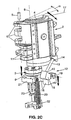
- Figure 2A is shown an external view of one of the half-molds 2 (we see the ears 11 on which are articulated the arms - not shown - actuated driven by the roller moved by the fixed cam of which question above ).
- the connecting means 12 interposed between the half-mold 2 and the mold base 3 comprise a connecting rod 13 provided at its two ends with spherical bearings to form a coupling respectively. 14 with the half-mold 2 and a coupling 15 with the mold bottom 3.
- the two couplings 14, 15 are ball couplings.
- one of the ball joints can be replaced by a cardan; alternatively, one and / or the other of these couplings may be replaced by any device providing the three degrees of freedom required to perform the aforementioned sequences.
- the coupling 14 is located on the outer wall of the half-mold 2, at a location thereof relatively far from the axis of rotation so as to have a sufficient amplitude of displacement.
- the coupling 15 is advantageously provided not on the bottom of the mold itself, but on the end of an arm 16 of radial extent, integral with the mold base 3, so that the rod 13 extends approximately parallel to the contact face 17 (joint plane) of the half-mold 2.
- the coupling 15 is integral with a moving part or rod 18 which, in the example illustrated in FIG. 2A, is embodied in the form of a solid shoe housing the spherical housing. receiving the spherical ball joint secured to the connecting rod 13.
- the shoe 18 is articulated to rotate on the end of the arm 16 by an axis 19 which, in the illustrated example, is substantially perpendicular to the axis 8 of the mold (or its pivot axis 5).
- elastic return means are associated with the mold base 3 to return it in the closed position.
- the spring 20 is interposed between a frame portion 21 of the molding device and a slideway 22 secured to each other. of the mold bottom 3 and cooperating with a fixed guide 23 for guiding the mold bottom 3 in its axial displacement.
- Figure 2A shows the half-mold 2 and the mold bottom 3 in the closed position (position also illustrated in Figure 1).
- one of these half-molds drives, via the connecting rod 13, the shoe 18 in a rotation about its axis 19 as shown in Figure 2B.
- the articulated connection between the shoe 18 and the arm 16 is arranged in such a manner (for example, as illustrated, the axis 19 is raised relative to the arm and the shoe 18 has a lower face having a cutaway 24) that the shoe 18 can rotate freely.
- the mold base 3 is not subject to any drive force and remains in its closed position, held by the spring 20.
- the half-mold 2 drives, via the connecting rod 13, the mold base 3 which reaches its raised position when the half-mold 2 still has an angular range ⁇ to Browse.
- the shoe 18 leaves its support on the abutment 25 of the arm 16 and, the mold base 3 then being kinematically separated from the half-mold 2, the latter completes only its closing path, with its groove 10 coming off the projection 9 of the mold bottom.
- the return force that the spring 20 exerts on the mold base 3 to tend to raise it to its raised position of closing the mold maintains the stop 25 of the arm 16 in contact of the shoe 18, so that the mold base 3 accompanies the movement of the half-mold 2.
- FIG. 3 (on which the mold 1 is shown as a whole, in perspective, at a different angle of view) illustrates the coupling 15 mounted at the end of an elongated rod 26. , itself connected at its other end, rotatably by an axis 27 approximately parallel to the axis 8 of the mold, to the arm 16 integral with the mold base 3.
- FIG. 3 illustrates the coupling 15 mounted at the end of an elongated rod 26. , itself connected at its other end, rotatably by an axis 27 approximately parallel to the axis 8 of the mold, to the arm 16 integral with the mold base 3.
Landscapes
- Engineering & Computer Science (AREA)
- Manufacturing & Machinery (AREA)
- Mechanical Engineering (AREA)
- Moulds For Moulding Plastics Or The Like (AREA)
- Blow-Moulding Or Thermoforming Of Plastics Or The Like (AREA)
- Shaping By String And By Release Of Stress In Plastics And The Like (AREA)
- Laminated Bodies (AREA)
Claims (9)
- Vorrichtung zum Formen von Behältern durch Blasen oder Streckblasen ausgehend von Rohlingen aus einem thermoplastischen Werkstoff, wobei die Vorrichtung eine Form (1) aus drei Teilen aufweist, nämlich zwei Halbformen (2) für den Körper des Behälters und einen Formboden (3) für den Boden des Behälters, wobei die unteren Teile der zwei Halbformen (2) und der obere Teil des Formbodens (3) Mittel (9, 10) aufweisen, die in der Schließposition der Form miteinander in Eingriff bringbar sind, um die axiale Steifigkeit der Form in Gegenwart des Blasdrucks sicherzustellen, wobei die zwei Halbformen (2) eingerichtet sind, um zueinander zwischen einer Öffnungsstellung und einer Schließstellung unter der Einwirkung von Betätigungsmitteln verschoben werden zu können, die von einem feststehenden Nocken gesteuert werden, wobei diese Vorrichtung Mittel zum Verbinden zwischen mindestens einer Halbform (2) und/oder den Betätigungsmitteln der Halbformen einerseits und dem Formboden (3) andererseits aufweist, so dass die Bewegung des Formbodens (3) von der Bewegung mindestens einer Halbform (2) und/oder des Betätigungsmittels gesteuert wird, so dass:• beim Öffnen der Form die Betätigungsmittel den Anfang der gegenseitigen Abspreizbewegung der Halbformen bewirken, bis die miteinander in Eingriff bringbaren Mittel (9, 10) voneinander freigegeben sind, während die Verbindungsmittel inaktiv bleiben und der Formboden in seiner Position bleibt, und dann, während die Betätigungsmittel die zwei Halbformen weiter spreizen, die Verbindungsmittel aktiv werden und den Formboden bewegen, um ihn axial von den genannten Halbformen zu trennen,und dass• beim Schließen der Form die Betätigungsmittel den Anfang des Annäherns der zwei Halbformen zur gleichen Zeit bewirken, wobei die Verbindungsmittel die axiale Bewegung des Formbodens bis zu seiner vollständig angehobenen Stellung steuern, und die Verbindungsmittel dann inaktiv werden und die Betätigungsmittel das Annähern der zwei Halbformen aneinander abschließen, wobei die ineinander steckbaren Mittel eingreifen, wodurch die zwei Halbformen und der Formboden mechanisch axial steif miteinander verbunden sind,dadurch gekennzeichnet, dass die Verbindungsmittel eine Verbindungsstange (13) aufweisen, deren Enden mit Kopplungsmitteln versehen sind, die drei Drehfreiheitsgrade haben, um sie jeweils mit der Halbform und/oder den Betätigungsmitteln der Halbformen und mit dem Formboden zu verbinden,
und dadurch, dass die Verbindung der Verbindungsstange (13) mit dem Formboden (3) vorgesehen ist, um beim Öffnen der Form frei unter dem Antrieb der Halbform und/oder der Betätigungsmittel der Halbformen zu schwenken, während sich die zwei Halbformen bis zu einem vorausbestimmten Winkelwert (α) öffnen, und um dann an einem Anschlag zur Auflage kommen, der fest mit dem Formboden (3) verbunden ist, während sich die Halbformen (2) um den Winkelwert (α) öffnen und/oder während die Betätigungsmittel in einer Stellung sind, bei der sich die Halbformen mit dem Winkelwert (α) öffnen, und schließlich den Formboden (3) zurückschieben, wenn die zwei Halbformen (2) ihren Öffnungsbewegung beenden, und umgekehrt beim Schließen der Form. - Formvorrichtung nach Anspruch 1, dadurch gekennzeichnet, dass die Verbindungsmittel zwischen einer der Halbformen (2) und dem Formboden (3) angeordnet sind.
- Formvorrichtung nach Anspruch 1 oder 2, dadurch gekennzeichnet, dass die Kopplungsmittel mit drei Drehfreiheitsgraden Kopplungen (14, 15) mit Kugelgelenken sind.
- Formvorrichtung nach Anspruch 1 oder 2, dadurch gekennzeichnet, dass die Kopplungsmittel mit drei Freiheitsgraden zum einen eine Kugelgelenkkopplung und zum andern eine Kardankopplung sind.
- Formvorrichtung nach Anspruch 3 oder 4, dadurch gekennzeichnet, dass das untere Ende der Verbindungsstange (13) über die Kopplung (15) jeweils mit einem Schwingarm (18) verbunden ist, der in Drehung durch einen radialen Arm (16) angelenkt ist, der fest mit dem Formboden verbunden ist, wobei der Anschlag aus einem Abschnitt (25) des Arms (16) gebildet ist.
- Formvorrichtung nach Anspruch 5, dadurch gekennzeichnet, dass der Schwingarm (18) durch den radialen Arm (16) in einer Achse (19) angelenkt ist, die zu der Achse der Form senkrecht ist.
- Formvorrichtung nach Anspruch 5 oder 6, dadurch gekennzeichnet, dass der Schwingarm (18) in Form eines massiven Schuhs ausgebildet ist, mit dem die entsprechende Kopplung (15) verbunden ist.
- Formvorrichtung nach einem der Ansprüche 1 bis 7, dadurch gekennzeichnet, dass elastische Rückholmittel (20) mit dem Formboden (3) gekoppelt sind, um die axiale Bewegung des Formbodens von seiner Öffnungsstellung bis zu seiner Schließstellung zu unterstützen.
- Formvorrichtung nach einem der Ansprüche 1 bis 8, dadurch gekennzeichnet, dass die Form (1) des Portefeuille-Typs mit zwei Halbformen (2) ist, die zueinander drehbar angelenkt sind.
Applications Claiming Priority (3)
| Application Number | Priority Date | Filing Date | Title |
|---|---|---|---|
| FR0208005A FR2841495B1 (fr) | 2002-06-27 | 2002-06-27 | Dispositif de moulage, par soufflage ou etirage-soufflage, de recipients en matiere thermoplastique |
| FR0208005 | 2002-06-27 | ||
| PCT/FR2003/001918 WO2004002716A1 (fr) | 2002-06-27 | 2003-06-23 | Dispositif de moulage, par soufflage ou etirage-soufflage, de recipients en matiere thermoplastique |
Publications (2)
| Publication Number | Publication Date |
|---|---|
| EP1549480A1 EP1549480A1 (de) | 2005-07-06 |
| EP1549480B1 true EP1549480B1 (de) | 2006-09-06 |
Family
ID=29724937
Family Applications (1)
| Application Number | Title | Priority Date | Filing Date |
|---|---|---|---|
| EP03761626A Expired - Lifetime EP1549480B1 (de) | 2002-06-27 | 2003-06-23 | Vorrichtung zum blasformen oder streckblasformen von behältern aus thermoplastischem material |
Country Status (9)
| Country | Link |
|---|---|
| US (1) | US7241130B2 (de) |
| EP (1) | EP1549480B1 (de) |
| AT (1) | ATE338624T1 (de) |
| AU (1) | AU2003258823A1 (de) |
| DE (1) | DE60308207T2 (de) |
| ES (1) | ES2273035T3 (de) |
| FR (1) | FR2841495B1 (de) |
| PT (1) | PT1549480E (de) |
| WO (1) | WO2004002716A1 (de) |
Families Citing this family (36)
| Publication number | Priority date | Publication date | Assignee | Title |
|---|---|---|---|---|
| FR2871721B1 (fr) | 2004-06-16 | 2006-09-29 | Sidel Sas | Installation de soufflage ou d'etirage-souflage a tuyere- cloche pour la fabrication de recipients en materiau thermoplastique et moule pour une telle installation |
| FR2873320B1 (fr) | 2004-07-20 | 2006-11-03 | Sidel Sas | Machine de soufflage pour le moulage de recipients comportant un fond de moule qui est sollicite vers le haut |
| DE102004045405A1 (de) * | 2004-09-18 | 2006-04-13 | Sig Technology Ltd. | Vorrichtung zur Blasformung von Behältern |
| US7951322B2 (en) * | 2006-06-13 | 2011-05-31 | Electroform Company | Method and apparatus for molding and assembling plural-part plastic assemblies |
| FR2912952B1 (fr) | 2007-02-27 | 2013-08-16 | Sidel Participations | Dispositif de moulage pour la fabrication de recipients en materiau thermoplastique |
| DE102007022638A1 (de) | 2007-05-15 | 2008-11-20 | Sig Technology Ag | Vorrichtung zur Blasformung von Behältern |
| FR2918046B1 (fr) | 2007-06-28 | 2009-09-18 | Sidel Participations | Dispositif de transfert d'objets avec un bras de transfert a tete de prehension mobile sensiblement verticalement |
| US8206143B2 (en) * | 2007-12-13 | 2012-06-26 | Biomet Manufacturing Corp. | Modular articulating cement spacer |
| IT1396853B1 (it) * | 2008-07-29 | 2012-12-20 | Sacmi Coop Mecc Imola Societa' Coop | Unita' di formatura di un impianto per il soffiaggio di contenitori di plastica, in particolare bottiglie |
| US8287270B2 (en) | 2009-09-30 | 2012-10-16 | Printpack Illinois Inc. | Methods and systems for thermoforming with billets |
| DE102010039803A1 (de) | 2010-08-26 | 2012-03-01 | Krones Aktiengesellschaft | Blasform |
| CH703721A1 (de) * | 2010-09-14 | 2012-03-15 | Alpla Werke | Blasformwerkzeug mit einem abhebbaren Formteil. |
| DE102010048720A1 (de) * | 2010-10-19 | 2012-04-19 | Krones Aktiengesellschaft | Schnellmontierbare Bodenform mit zuschaltbarer Haltekraftunterstützung |
| DE102010051544A1 (de) * | 2010-11-18 | 2012-06-06 | Krones Aktiengesellschaft | Bodenformhubdämpfung |
| US9937047B2 (en) * | 2011-12-06 | 2018-04-10 | Zimmer, Inc. | Spacer mold for orthopedic implants |
| CN102962985B (zh) * | 2012-11-22 | 2014-09-17 | 广州达意隆包装机械股份有限公司 | 一种吹瓶机的底模与模架联动连杆机构 |
| CN103171132B (zh) * | 2013-03-19 | 2015-05-20 | 江苏新美星包装机械股份有限公司 | 一种单轴开合模、底模定位联动机构 |
| CN103171136B (zh) * | 2013-03-19 | 2015-05-20 | 江苏新美星包装机械股份有限公司 | 一种底模升降、双边定位联动机构 |
| CN103171131B (zh) * | 2013-03-19 | 2014-12-31 | 江苏新美星包装机械股份有限公司 | 一种底模双边锁定机构 |
| CN103171135B (zh) * | 2013-03-19 | 2014-12-31 | 江苏新美星包装机械股份有限公司 | 单轴开合模、底模定位联动机构 |
| CN103171126B (zh) * | 2013-03-19 | 2015-07-01 | 江苏新美星包装机械股份有限公司 | 一种吹瓶机 |
| CN103171137B (zh) * | 2013-03-19 | 2015-02-11 | 江苏新美星包装机械股份有限公司 | 一种底模升降、单边锁定联动机构 |
| DE102013104995A1 (de) * | 2013-05-15 | 2014-11-20 | Krones Ag | Blasformmaschine mit separater Druckkissenansteuerung |
| CN103692642B (zh) * | 2013-12-23 | 2016-01-20 | 冯伟君 | 吹塑机的模架结构 |
| EP3102383B1 (de) * | 2014-01-22 | 2018-04-04 | S.I.P.A. Società Industrializzazione Progettazione e Automazione S.p.A. | Blasform zum blasen von behältern aus thermoplastischem material |
| DE102014101853A1 (de) | 2014-02-13 | 2015-08-13 | Krones Ag | Blasformmaschine mit Zentrierung des Blasformbodens |
| DE102015117017A1 (de) * | 2015-10-06 | 2017-04-06 | Krones Ag | Vorrichtung und Verfahren zum Umformen von Kunststoffvorformlingen zu Kunststoffbehältnissen mit Kopplungseinrichtung |
| FR3043932B1 (fr) | 2015-11-25 | 2017-11-24 | Sidel Participations | Procede de commande d'une unite de moulage |
| ITUB20155974A1 (it) | 2015-11-27 | 2017-05-27 | Sacmi Imola Sc | Dispositivo per il soffiaggio di contenitori. |
| CN106493935A (zh) * | 2016-11-16 | 2017-03-15 | 江苏辉河包装机械有限公司 | 旋转式吹瓶机的合模与底模联动机构 |
| MX2019008141A (es) * | 2017-01-06 | 2019-12-09 | Friendship Products Llc | Sistemas de moldeo y metodos relacionados. |
| CN108790109B (zh) * | 2018-08-10 | 2024-04-26 | 苏州同大机械有限公司 | 吹塑机的料坯移动装置 |
| DE102018123624A1 (de) * | 2018-09-25 | 2020-03-26 | Krones Ag | Vorrichtung zum Umformen von Kunststoffvorformlingen zu Kunststoffbehältnissen sowie eine Blasform und ein Verfahren zur Herstellung eines Behältnisses |
| CN109263023B (zh) * | 2018-11-15 | 2023-07-14 | 江苏新美星包装机械股份有限公司 | 一种用于吹瓶机模架联动的连杆机构 |
| CN111645302B (zh) * | 2020-05-26 | 2025-02-28 | 江苏新美星包装机械股份有限公司 | 一种吹瓶机动边模与底模联动的组合连杆机构 |
| JP2022125007A (ja) | 2021-02-16 | 2022-08-26 | サクミ・イモラ・ソシエタ・コーペラティバ | 容器をブロー成形するための装置 |
Family Cites Families (7)
| Publication number | Priority date | Publication date | Assignee | Title |
|---|---|---|---|---|
| DE1100936B (de) * | 1958-07-26 | 1961-03-02 | Kautex Werke Gmbh | Verfahren und Vorrichtung zum Herstellen von Tuben aus thermoplastischem Kunststoff |
| US3267184A (en) * | 1963-12-04 | 1966-08-16 | Owens Illinois Inc | Method and apparatus for molding plastic articles |
| US3856450A (en) * | 1972-11-06 | 1974-12-24 | Manbritt Ind Inc | Mold construction |
| US4290745A (en) * | 1979-01-09 | 1981-09-22 | Owens-Illinois, Inc. | Apparatus for blow molding |
| US5064366A (en) * | 1990-05-15 | 1991-11-12 | Nissei Asb Machine Co., Ltd. | Blow mold |
| US5240402A (en) * | 1992-11-23 | 1993-08-31 | Husky Injection Molding Systems Ltd. | Apparatus for preparing hollow plastic article |
| US6824377B2 (en) * | 2003-02-07 | 2004-11-30 | R&D Tool & Engineering Co. | Blow station bottom plug actuating mechanism |
-
2002
- 2002-06-27 FR FR0208005A patent/FR2841495B1/fr not_active Expired - Fee Related
-
2003
- 2003-06-23 AT AT03761626T patent/ATE338624T1/de not_active IP Right Cessation
- 2003-06-23 PT PT03761626T patent/PT1549480E/pt unknown
- 2003-06-23 WO PCT/FR2003/001918 patent/WO2004002716A1/fr not_active Ceased
- 2003-06-23 AU AU2003258823A patent/AU2003258823A1/en not_active Abandoned
- 2003-06-23 US US10/517,207 patent/US7241130B2/en not_active Expired - Fee Related
- 2003-06-23 DE DE60308207T patent/DE60308207T2/de not_active Expired - Lifetime
- 2003-06-23 ES ES03761626T patent/ES2273035T3/es not_active Expired - Lifetime
- 2003-06-23 EP EP03761626A patent/EP1549480B1/de not_active Expired - Lifetime
Also Published As
| Publication number | Publication date |
|---|---|
| US7241130B2 (en) | 2007-07-10 |
| FR2841495A1 (fr) | 2004-01-02 |
| EP1549480A1 (de) | 2005-07-06 |
| PT1549480E (pt) | 2007-01-31 |
| ATE338624T1 (de) | 2006-09-15 |
| WO2004002716A1 (fr) | 2004-01-08 |
| AU2003258823A1 (en) | 2004-01-19 |
| ES2273035T3 (es) | 2007-05-01 |
| US20060093699A1 (en) | 2006-05-04 |
| FR2841495B1 (fr) | 2004-11-12 |
| DE60308207D1 (de) | 2006-10-19 |
| DE60308207T2 (de) | 2007-08-02 |
Similar Documents
| Publication | Publication Date | Title |
|---|---|---|
| EP1549480A1 (de) | Vorrichtung zum blasformen oder streckblasformen von behältern aus thermoplastischem material | |
| EP1694483B1 (de) | Formvorrichtung zur herstellung von aus thermoplastischem material hergestellten behältnissen | |
| CA2529753C (fr) | Dispositif de moulage pour la fabrication de recipients en materiau thermoplastique | |
| EP1636006B1 (de) | Formvorrichtung zur herstellung von behältern aus thermoplastischem material | |
| EP1768831A1 (de) | Blasformmaschine zum formen von behältern mit einer nach oben vorbelasteten formbasis | |
| EP1216136B1 (de) | Blasformmaschine mit einem schliess- und verriegelungsmechanismus | |
| EP1846219B1 (de) | Verfahren zum steuern des öffnens und schliessens einer blasform und blasvorrichtung zur entsprechenden durchführung | |
| FR2881677A1 (fr) | Dispositif rotatif de transfert de recipients | |
| EP2661352B1 (de) | Vorrichtung zum blasformen von behältern | |
| EP2861406B1 (de) | Vorrichtung zum blasformen von behältern | |
| FR2659265A1 (fr) | Procede de dispositif pour fabriquer des recipients en matieres thermoplastiques par soufflage ou etirage-soufflage. | |
| EP3057767B1 (de) | Formeinheit zur herstellung von behältern mit einem kompensationsgreifer | |
| FR2646802A1 (fr) | Dispositif de verrouillage pour moule de type portefeuilles et moules incorporant un tel dispositif | |
| FR2522643A1 (fr) | Support et mandrin de prehension d'articles pour machine de moulage par soufflage | |
| FR2774666A1 (fr) | Dispositif de transfert pour corps creux possedant un goulot | |
| FR2720679A1 (fr) | Bras de transfert et machine de fabrication de bouteilles à partir de préforme utilisant un tel bras. | |
| FR2888154A1 (fr) | Unites de moulage et machine de moulage a pas vaviable | |
| EP4031350B1 (de) | Formeinheit mit verriegelung mittels haken | |
| FR2945980A1 (fr) | Systeme d'ouverture et fermeture d'un moule portefeuiile | |
| EP4457076B1 (de) | Vorrichtung zum blasformen oder streckblasformen von thermoplastischen behältern |
Legal Events
| Date | Code | Title | Description |
|---|---|---|---|
| PUAI | Public reference made under article 153(3) epc to a published international application that has entered the european phase |
Free format text: ORIGINAL CODE: 0009012 |
|
| 17P | Request for examination filed |
Effective date: 20041129 |
|
| AK | Designated contracting states |
Kind code of ref document: A1 Designated state(s): AT BE BG CH CY CZ DE DK EE ES FI FR GB GR HU IE IT LI LU MC NL PT RO SE SI SK TR |
|
| AX | Request for extension of the european patent |
Extension state: AL LT LV MK |
|
| DAX | Request for extension of the european patent (deleted) | ||
| GRAP | Despatch of communication of intention to grant a patent |
Free format text: ORIGINAL CODE: EPIDOSNIGR1 |
|
| RAP1 | Party data changed (applicant data changed or rights of an application transferred) |
Owner name: SIDEL PARTICIPATIONS |
|
| RIC1 | Information provided on ipc code assigned before grant |
Ipc: B29C 49/36 20060101ALI20060426BHEP Ipc: B29C 49/54 20060101AFI20060426BHEP Ipc: B29C 49/56 20060101ALI20060426BHEP |
|
| GRAS | Grant fee paid |
Free format text: ORIGINAL CODE: EPIDOSNIGR3 |
|
| GRAA | (expected) grant |
Free format text: ORIGINAL CODE: 0009210 |
|
| AK | Designated contracting states |
Kind code of ref document: B1 Designated state(s): AT BE BG CH CY CZ DE DK EE ES FI FR GB GR HU IE IT LI LU MC NL PT RO SE SI SK TR |
|
| PG25 | Lapsed in a contracting state [announced via postgrant information from national office to epo] |
Ref country code: SK Free format text: LAPSE BECAUSE OF FAILURE TO SUBMIT A TRANSLATION OF THE DESCRIPTION OR TO PAY THE FEE WITHIN THE PRESCRIBED TIME-LIMIT Effective date: 20060906 Ref country code: AT Free format text: LAPSE BECAUSE OF FAILURE TO SUBMIT A TRANSLATION OF THE DESCRIPTION OR TO PAY THE FEE WITHIN THE PRESCRIBED TIME-LIMIT Effective date: 20060906 Ref country code: NL Free format text: LAPSE BECAUSE OF FAILURE TO SUBMIT A TRANSLATION OF THE DESCRIPTION OR TO PAY THE FEE WITHIN THE PRESCRIBED TIME-LIMIT Effective date: 20060906 Ref country code: FI Free format text: LAPSE BECAUSE OF FAILURE TO SUBMIT A TRANSLATION OF THE DESCRIPTION OR TO PAY THE FEE WITHIN THE PRESCRIBED TIME-LIMIT Effective date: 20060906 Ref country code: RO Free format text: LAPSE BECAUSE OF FAILURE TO SUBMIT A TRANSLATION OF THE DESCRIPTION OR TO PAY THE FEE WITHIN THE PRESCRIBED TIME-LIMIT Effective date: 20060906 Ref country code: SI Free format text: LAPSE BECAUSE OF FAILURE TO SUBMIT A TRANSLATION OF THE DESCRIPTION OR TO PAY THE FEE WITHIN THE PRESCRIBED TIME-LIMIT Effective date: 20060906 Ref country code: IE Free format text: LAPSE BECAUSE OF FAILURE TO SUBMIT A TRANSLATION OF THE DESCRIPTION OR TO PAY THE FEE WITHIN THE PRESCRIBED TIME-LIMIT Effective date: 20060906 Ref country code: CZ Free format text: LAPSE BECAUSE OF FAILURE TO SUBMIT A TRANSLATION OF THE DESCRIPTION OR TO PAY THE FEE WITHIN THE PRESCRIBED TIME-LIMIT Effective date: 20060906 Ref country code: IT Free format text: LAPSE BECAUSE OF FAILURE TO SUBMIT A TRANSLATION OF THE DESCRIPTION OR TO PAY THE FEE WITHIN THE PRESCRIBED TIME-LIMIT;WARNING: LAPSES OF ITALIAN PATENTS WITH EFFECTIVE DATE BEFORE 2007 MAY HAVE OCCURRED AT ANY TIME BEFORE 2007. THE CORRECT EFFECTIVE DATE MAY BE DIFFERENT FROM THE ONE RECORDED. Effective date: 20060906 |
|
| REG | Reference to a national code |
Ref country code: GB Ref legal event code: FG4D Free format text: NOT ENGLISH |
|
| REG | Reference to a national code |
Ref country code: CH Ref legal event code: EP |
|
| REG | Reference to a national code |
Ref country code: IE Ref legal event code: FG4D Free format text: LANGUAGE OF EP DOCUMENT: FRENCH |
|
| REF | Corresponds to: |
Ref document number: 60308207 Country of ref document: DE Date of ref document: 20061019 Kind code of ref document: P |
|
| PG25 | Lapsed in a contracting state [announced via postgrant information from national office to epo] |
Ref country code: SE Free format text: LAPSE BECAUSE OF FAILURE TO SUBMIT A TRANSLATION OF THE DESCRIPTION OR TO PAY THE FEE WITHIN THE PRESCRIBED TIME-LIMIT Effective date: 20061206 Ref country code: DK Free format text: LAPSE BECAUSE OF FAILURE TO SUBMIT A TRANSLATION OF THE DESCRIPTION OR TO PAY THE FEE WITHIN THE PRESCRIBED TIME-LIMIT Effective date: 20061206 Ref country code: BG Free format text: LAPSE BECAUSE OF FAILURE TO SUBMIT A TRANSLATION OF THE DESCRIPTION OR TO PAY THE FEE WITHIN THE PRESCRIBED TIME-LIMIT Effective date: 20061206 |
|
| GBT | Gb: translation of ep patent filed (gb section 77(6)(a)/1977) |
Effective date: 20061220 |
|
| REG | Reference to a national code |
Ref country code: PT Ref legal event code: SC4A Free format text: AVAILABILITY OF NATIONAL TRANSLATION Effective date: 20061130 |
|
| NLV1 | Nl: lapsed or annulled due to failure to fulfill the requirements of art. 29p and 29m of the patents act | ||
| REG | Reference to a national code |
Ref country code: IE Ref legal event code: FD4D |
|
| REG | Reference to a national code |
Ref country code: ES Ref legal event code: FG2A Ref document number: 2273035 Country of ref document: ES Kind code of ref document: T3 |
|
| PLBE | No opposition filed within time limit |
Free format text: ORIGINAL CODE: 0009261 |
|
| STAA | Information on the status of an ep patent application or granted ep patent |
Free format text: STATUS: NO OPPOSITION FILED WITHIN TIME LIMIT |
|
| 26N | No opposition filed |
Effective date: 20070607 |
|
| BERE | Be: lapsed |
Owner name: SIDEL PARTICIPATIONS Effective date: 20070630 |
|
| PG25 | Lapsed in a contracting state [announced via postgrant information from national office to epo] |
Ref country code: MC Free format text: LAPSE BECAUSE OF NON-PAYMENT OF DUE FEES Effective date: 20070630 |
|
| REG | Reference to a national code |
Ref country code: CH Ref legal event code: PL |
|
| PG25 | Lapsed in a contracting state [announced via postgrant information from national office to epo] |
Ref country code: BE Free format text: LAPSE BECAUSE OF NON-PAYMENT OF DUE FEES Effective date: 20070630 |
|
| PG25 | Lapsed in a contracting state [announced via postgrant information from national office to epo] |
Ref country code: LI Free format text: LAPSE BECAUSE OF NON-PAYMENT OF DUE FEES Effective date: 20070630 Ref country code: GR Free format text: LAPSE BECAUSE OF FAILURE TO SUBMIT A TRANSLATION OF THE DESCRIPTION OR TO PAY THE FEE WITHIN THE PRESCRIBED TIME-LIMIT Effective date: 20061207 Ref country code: CH Free format text: LAPSE BECAUSE OF NON-PAYMENT OF DUE FEES Effective date: 20070630 |
|
| PG25 | Lapsed in a contracting state [announced via postgrant information from national office to epo] |
Ref country code: EE Free format text: LAPSE BECAUSE OF FAILURE TO SUBMIT A TRANSLATION OF THE DESCRIPTION OR TO PAY THE FEE WITHIN THE PRESCRIBED TIME-LIMIT Effective date: 20060906 |
|
| PG25 | Lapsed in a contracting state [announced via postgrant information from national office to epo] |
Ref country code: LU Free format text: LAPSE BECAUSE OF NON-PAYMENT OF DUE FEES Effective date: 20070623 Ref country code: CY Free format text: LAPSE BECAUSE OF FAILURE TO SUBMIT A TRANSLATION OF THE DESCRIPTION OR TO PAY THE FEE WITHIN THE PRESCRIBED TIME-LIMIT Effective date: 20060906 |
|
| PG25 | Lapsed in a contracting state [announced via postgrant information from national office to epo] |
Ref country code: HU Free format text: LAPSE BECAUSE OF FAILURE TO SUBMIT A TRANSLATION OF THE DESCRIPTION OR TO PAY THE FEE WITHIN THE PRESCRIBED TIME-LIMIT Effective date: 20070307 Ref country code: TR Free format text: LAPSE BECAUSE OF FAILURE TO SUBMIT A TRANSLATION OF THE DESCRIPTION OR TO PAY THE FEE WITHIN THE PRESCRIBED TIME-LIMIT Effective date: 20060906 |
|
| REG | Reference to a national code |
Ref country code: FR Ref legal event code: PLFP Year of fee payment: 13 |
|
| PGFP | Annual fee paid to national office [announced via postgrant information from national office to epo] |
Ref country code: PT Payment date: 20150608 Year of fee payment: 13 |
|
| REG | Reference to a national code |
Ref country code: FR Ref legal event code: PLFP Year of fee payment: 14 |
|
| PGFP | Annual fee paid to national office [announced via postgrant information from national office to epo] |
Ref country code: GB Payment date: 20160527 Year of fee payment: 14 Ref country code: ES Payment date: 20160525 Year of fee payment: 14 |
|
| PG25 | Lapsed in a contracting state [announced via postgrant information from national office to epo] |
Ref country code: PT Free format text: LAPSE BECAUSE OF NON-PAYMENT OF DUE FEES Effective date: 20161223 |
|
| REG | Reference to a national code |
Ref country code: FR Ref legal event code: PLFP Year of fee payment: 15 |
|
| GBPC | Gb: european patent ceased through non-payment of renewal fee |
Effective date: 20170623 |
|
| PG25 | Lapsed in a contracting state [announced via postgrant information from national office to epo] |
Ref country code: GB Free format text: LAPSE BECAUSE OF NON-PAYMENT OF DUE FEES Effective date: 20170623 |
|
| REG | Reference to a national code |
Ref country code: FR Ref legal event code: PLFP Year of fee payment: 16 |
|
| PGFP | Annual fee paid to national office [announced via postgrant information from national office to epo] |
Ref country code: DE Payment date: 20180522 Year of fee payment: 16 |
|
| PGFP | Annual fee paid to national office [announced via postgrant information from national office to epo] |
Ref country code: IT Payment date: 20180523 Year of fee payment: 16 Ref country code: FR Payment date: 20180525 Year of fee payment: 16 |
|
| REG | Reference to a national code |
Ref country code: ES Ref legal event code: FD2A Effective date: 20181107 |
|
| PG25 | Lapsed in a contracting state [announced via postgrant information from national office to epo] |
Ref country code: ES Free format text: LAPSE BECAUSE OF NON-PAYMENT OF DUE FEES Effective date: 20170624 |
|
| REG | Reference to a national code |
Ref country code: DE Ref legal event code: R119 Ref document number: 60308207 Country of ref document: DE |
|
| PG25 | Lapsed in a contracting state [announced via postgrant information from national office to epo] |
Ref country code: IT Free format text: LAPSE BECAUSE OF NON-PAYMENT OF DUE FEES Effective date: 20190623 Ref country code: DE Free format text: LAPSE BECAUSE OF NON-PAYMENT OF DUE FEES Effective date: 20200101 |
|
| PG25 | Lapsed in a contracting state [announced via postgrant information from national office to epo] |
Ref country code: FR Free format text: LAPSE BECAUSE OF NON-PAYMENT OF DUE FEES Effective date: 20190630 |