EP1549972B1 - Procede de determination de la distance entre deux stations emettrices-receptrices et stations emettrices-receptrices correspondantes - Google Patents
Procede de determination de la distance entre deux stations emettrices-receptrices et stations emettrices-receptrices correspondantes Download PDFInfo
- Publication number
- EP1549972B1 EP1549972B1 EP03750326A EP03750326A EP1549972B1 EP 1549972 B1 EP1549972 B1 EP 1549972B1 EP 03750326 A EP03750326 A EP 03750326A EP 03750326 A EP03750326 A EP 03750326A EP 1549972 B1 EP1549972 B1 EP 1549972B1
- Authority
- EP
- European Patent Office
- Prior art keywords
- data
- transmission
- counter
- receiving
- bit
- Prior art date
- Legal status (The legal status is an assumption and is not a legal conclusion. Google has not performed a legal analysis and makes no representation as to the accuracy of the status listed.)
- Expired - Lifetime
Links
Images

Classifications
-
- G—PHYSICS
- G07—CHECKING-DEVICES
- G07C—TIME OR ATTENDANCE REGISTERS; REGISTERING OR INDICATING THE WORKING OF MACHINES; GENERATING RANDOM NUMBERS; VOTING OR LOTTERY APPARATUS; ARRANGEMENTS, SYSTEMS OR APPARATUS FOR CHECKING NOT PROVIDED FOR ELSEWHERE
- G07C9/00—Individual registration on entry or exit
- G07C9/00174—Electronically operated locks; Circuits therefor; Nonmechanical keys therefor, e.g. passive or active electrical keys or other data carriers without mechanical keys
- G07C9/00309—Electronically operated locks; Circuits therefor; Nonmechanical keys therefor, e.g. passive or active electrical keys or other data carriers without mechanical keys operated with bidirectional data transmission between data carrier and locks
-
- G—PHYSICS
- G01—MEASURING; TESTING
- G01S—RADIO DIRECTION-FINDING; RADIO NAVIGATION; DETERMINING DISTANCE OR VELOCITY BY USE OF RADIO WAVES; LOCATING OR PRESENCE-DETECTING BY USE OF THE REFLECTION OR RERADIATION OF RADIO WAVES; ANALOGOUS ARRANGEMENTS USING OTHER WAVES
- G01S13/00—Systems using the reflection or reradiation of radio waves, e.g. radar systems; Analogous systems using reflection or reradiation of waves whose nature or wavelength is irrelevant or unspecified
- G01S13/74—Systems using reradiation of radio waves, e.g. secondary radar systems; Analogous systems
- G01S13/76—Systems using reradiation of radio waves, e.g. secondary radar systems; Analogous systems wherein pulse-type signals are transmitted
- G01S13/765—Systems using reradiation of radio waves, e.g. secondary radar systems; Analogous systems wherein pulse-type signals are transmitted with exchange of information between interrogator and responder
-
- G—PHYSICS
- G07—CHECKING-DEVICES
- G07C—TIME OR ATTENDANCE REGISTERS; REGISTERING OR INDICATING THE WORKING OF MACHINES; GENERATING RANDOM NUMBERS; VOTING OR LOTTERY APPARATUS; ARRANGEMENTS, SYSTEMS OR APPARATUS FOR CHECKING NOT PROVIDED FOR ELSEWHERE
- G07C9/00—Individual registration on entry or exit
- G07C9/00174—Electronically operated locks; Circuits therefor; Nonmechanical keys therefor, e.g. passive or active electrical keys or other data carriers without mechanical keys
- G07C2009/00753—Electronically operated locks; Circuits therefor; Nonmechanical keys therefor, e.g. passive or active electrical keys or other data carriers without mechanical keys operated by active electrical keys
- G07C2009/00769—Electronically operated locks; Circuits therefor; Nonmechanical keys therefor, e.g. passive or active electrical keys or other data carriers without mechanical keys operated by active electrical keys with data transmission performed by wireless means
- G07C2009/00793—Electronically operated locks; Circuits therefor; Nonmechanical keys therefor, e.g. passive or active electrical keys or other data carriers without mechanical keys operated by active electrical keys with data transmission performed by wireless means by Hertzian waves
-
- G—PHYSICS
- G07—CHECKING-DEVICES
- G07C—TIME OR ATTENDANCE REGISTERS; REGISTERING OR INDICATING THE WORKING OF MACHINES; GENERATING RANDOM NUMBERS; VOTING OR LOTTERY APPARATUS; ARRANGEMENTS, SYSTEMS OR APPARATUS FOR CHECKING NOT PROVIDED FOR ELSEWHERE
- G07C2209/00—Indexing scheme relating to groups G07C9/00 - G07C9/38
- G07C2209/60—Indexing scheme relating to groups G07C9/00174 - G07C9/00944
- G07C2209/63—Comprising locating means for detecting the position of the data carrier, i.e. within the vehicle or within a certain distance from the vehicle
Definitions
- the invention relates to a method for determining the distance between two transceiver stations according to claim 1. It further relates to a transceiver station for performing the method.
- a method according to the preamble of claim 1 is known for example from DE 100 19 277 A1.
- a radio connection for transmitting data is established between an electronic key module to be carried by a user and an evaluation unit provided in a motor vehicle in order to identify the key module by means of an identification number stored in the key module, and to release the motor vehicle for use if necessary ,
- the structure of the radio connection is carried out via a provided in the key module and provided in the evaluation unit transmitting-receiving station.
- the distance between the key module and the evaluation is determined and prevents the release of the motor vehicle when the key module is not in the vicinity of the evaluation located. The distance determination is based on a signal propagation time evaluation of the signals transmitted via the radio link.
- the invention has for its object to provide a method for determining the distance between two transceiver stations, which can be carried out with little effort and based on the evaluation of signals that usually used in vehicles in locking systems for driving authorization and access control.
- the invention is further based on the object of specifying a transmitting-receiving station for carrying out the method.
- At least three data telegrams with at least one data bit in each case, preferably with the same number of data bits, are alternately transmitted between the transceiver stations.
- each data bit of the relevant data telegram is assigned a counter value corresponding to the count of a free-running counter and each of the at least three data telegrams is assigned a count sum as the sum or average of the counter values determined during the reception of the relevant data telegram.
- the counts are summed by weighted summation to a sum number which is a measure of the distance between the transmit-receive stations.
- the count sums are weighted at the weighted summation each having a Binominialkostoryen corresponding to their order, wherein the order of the count sums is predetermined by the order of the data telegrams to which the count sums are assigned.
- information about the count sums determined in the one send-receive station is transmitted as part of a data telegram to the respective other send-receive station.
- four data telegrams are evaluated for distance determination.
- a pause of a predetermined duration is maintained between the transmitted data telegrams.
- a transmitting-receiving station for carrying out the method according to the invention comprises a transmitting-receiving antenna for receiving a preferably modulated by amplitude shift received signal and for transmitting a similarly modulated transmit signal, a receiver arrangement for detecting data bits from the received signal, a transmitter arrangement for generating the transmit signal from a sequence of data bits to be transmitted, a clock clocked at a predetermined timing for generating a bit clock corresponding to the time interval between successive meter overflows, which determines the times at which the data bits to be transmitted are sent out, and a register for accepting the count of the counter at the time the reception of a data bit and for the provision of the accepted meter reading as a counter value of the respective data bit.
- the transceiver station further comprises a pulse width modulator clocked in accordance with the bit clock, which generates a binary transmission data signal from the data bits to be transmitted by pulse width modulation, from which the transmitter arrangement in turn generates the transmission signal.
- a pulse width modulator clocked in accordance with the bit clock, which generates a binary transmission data signal from the data bits to be transmitted by pulse width modulation, from which the transmitter arrangement in turn generates the transmission signal.
- the transceiver station has a switch via which the transceiver antenna is respectively conductively connected to either the receiver arrangement or to the transmitter arrangement in accordance with the desired transmission direction.
- the transceiver station preferably has a microcontroller for evaluating the determined counter values and for providing the data bits to be transmitted by the transceiver station.
- the inventive method is ideally suited for use in locking systems for driving authorization and access control for motor vehicles.
- data is exchanged between a base station provided in the motor vehicle and a portable key module in order to check whether the key module is assigned an access authorization and / or driving correction and access to the user of the key module according to the present or not present access or driving authorization to the motor vehicle or access to the motor vehicle grant or deny.
- the data transmission takes place via a radio link usually in so-called ISM bands at 433 MHz or 868 MHz.
- the method according to the invention now makes it possible to measure the distance between the key module and the base station in addition to the access and driving authorization control when using the same radio bands. Distance resolutions of a few meters can be achieved.
- the distance measurement it is possible to deny the access and driving authorization, although the key module is assigned an access and driving authorization, but his distance from the base station is so large that unauthorized persons could obtain unnoticed by the authorized user access to the vehicle.
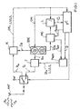
- the transceiver station comprises a transceiver antenna ANT, a switch SW, a receiver arrangement R, a transmitter arrangement T, a quartz-stable oscillator arrangement OSC, a counter MC, a register L, a digital control unit designed as a microcontroller ⁇ C and a pulse width modulator PWM.
- two of these transmit-receive stations are required. These are operated alternately in a transmission mode or reception mode. In the transmission mode, the one transmitting-receiving station transmits a transmission signal Tx to the other transmitting-receiving station which is currently operating in the receive mode and receives the transmit signal Tx after its delay in the transmission path as a receive signal Rx.
- the operating mode of the transceiver stations is determined by the switch position of their switch SW and controlled by the microcontroller ⁇ C.
- the switch SW In the transmission mode, the switch SW is in the lower position shown in dashed lines.
- the pulse width modulator PWM generates from data D, which are provided by the microcontroller .mu.C, a binary pulse-width-modulated transmission data signal DTx in accordance with a bit clock Tbit.
- a signal is composed of a sequence of pulses with either equidistant rising or equidistant falling pulse edges, the pulses containing in their pulse width the bit information to be transmitted with the respective pulse.
- Such a pulse series is referred to below as a data telegram.
- a narrow pulse of the bit information corresponds to "0" and a broad pulse of the bit information "1" and the rising pulse edges are spaced apart in the bit clock Tbit.
- the data bits are thus transmitted in succession in each case after expiration of a bit clock Tbit.
- the transmission data signal DTx is then modulated in the transmission arrangement T by amplitude shift keying on a carrier and passed as a transmission signal Tx via the switch SW to the transmitting-receiving antenna ANT and emitted from this as an electromagnetic wave.
- the carrier frequency ftx of the transmission signal Tx is provided by the oscillator arrangement OSC in accordance with a control signal Ctrl delivered by the microcontroller .mu.C.
- the oscillator arrangement OSC also provides a count clock Tclk as a time base for the counter MC, from which the counter MC derives the bit clock Tbit by counting the count clocks Tclk as a time interval between two counter overflows.
- the switch SW In the reception operating mode, the switch SW is in the upper position. In this operating mode, the receive signal Rx received via the transmit-receive antenna ANT is forwarded via the switch SW to the receiver arrangement R, where it is filtered by amplification, mixing with a local oscillator frequency f 0 provided by the oscillator arrangement OSC and envelope demodulation implemented as a binary pulse width modulated receive data signal DRx in the base frequency band.
- the received data signal DRx is then fed to the microcontroller ⁇ C for extraction of the bit information contained in it.
- the received data signal DRx is supplied to the register L, which stores the state of the counter MC at the time of receipt of each individual data bit and provides the microcontroller .mu.C as a counter value Ci for further evaluation.
- At least three, preferably four, data telegrams T1, T2, T3, T4 are transmitted according to FIG. Between the individual data telegrams identical breaks Tpause be respected.
- the transmitted data telegrams are each composed of three bit blocks, namely a header D0, a start block D1 and a data block D2.
- the header D0 consists of a series of identical bits. He has the task to bring the receiving device R in a stable operating condition, eg. B. by adjusting the signal level of the converted into an intermediate frequency range received signal Rx to a predetermined signal level.
- the start block D1 consists of at least one bit and has the task to mark the beginning of the subsequent data block D2.
- the data block D2 finally contains the actual data bits to be transmitted.
- the number of data bits can vary from data telegram to data telegram, but below it is assumed that all data telegrams contain the same number n of data bits in their data blocks.
- the determination of the distance between the transceiver stations is based on the determination of the signal propagation time of the data telegrams transmitted between the transceiver stations.
- the determination of the signal transit time is in turn based on the evaluation of the reception times of the individual data bits from the received signal Rx.
- the count of the counter MC is transferred to the register L with each rising pulse edge of the received data signal DRx which marks the receipt of a data bit.
- the counter MC is provided with a Counting clock Tclk predetermined clock signal clocked and his meter reading thereby increased by one. After an overflow of the count, the counter MC starts to count up again from a count of zero.
- the frequency of the clock signals is approximately equal in both transmit-receive stations.
- the count taken from the register L is output as counter value Ci to the microcontroller .mu.C for evaluation.
- each receiving data bit is assigned a time stamp on the rising pulse edge of the received data signal DRx, corresponding to the counter value Ci of the free-running counter MC.
- the counter MC acts as an internal clock of the relevant transceiver station. It can be reset by the microcontroller ⁇ C via a reset line reset for synchronization with the corresponding counter of the other transceiver station.
- the counter readings of the counters MC from the two transceiver stations are hereinafter referred to as C A and C B , and the corresponding counter values C i determined when the data bits are received are denoted by C Ai and C Bi .
- the indices A and B indicate that the relevant counter reading C A or C B and the respective counter value C Ai or C Bi has been determined in the first or second transceiver station.
- the two counts C A and C B differ from each other, because the counters MC of the two transceiver stations run independently of each other.
- the cause of this count error .DELTA.C F are only approximately the same count clocks Tclk in the two transmit-receive stations.
- the difference between the count clocks Tclk causes the counter MC of one transceiver station to advance or to run counter to the counter MC of the other transceiver station.
- the counting error .DELTA.C F indicates how much the one counter MC runs before or after the other per bit clock Tbit.
- the inventive method now provides that between the two transceiver station at least three, preferably four data telegrams are exchanged and that for each data telegram the sum or the average value of the counter values determined during the reception of the relevant data telegram is calculated and made available in one of the two transceiver stations, which then performs the distance calculation.
- the method is started by the first transceiver station with the transmission of a first data telegram.
- the individual bits of the data telegram are transmitted one after the other at a zero crossing of the counter reading C A , ie the bits are transmitted synchronously with the bit clock Tbit generated in the first transmit-receive station.
- the second transceiver station receives the first data telegram and resets its own counter MC during the preamble.
- the counters MC of the two transceiver stations are thus approximately synchronized, a precise synchronization is not required.
- the synchronization takes place during the distance determination only once upon receipt of the first data telegram.
- the associated counter value C Bi is then determined for each received data bit in the second transmit-receive station and stored as a time stamp of the relevant data bit in the microcontroller, ⁇ C.
- ⁇ C the relevant data bit in the microcontroller
- ⁇ C 0 stands for the initial meter reading offset
- ⁇ C F for the counting error caused by the different counting clocks Tclk
- ⁇ C SBi for the meter reading difference resulting from the signal propagation delay
- the data telegram contains a total of n data bits.
- the second transceiver station answers the receipt of the first data telegram with the transmission of a second data telegram, which contains information about the first counted sum S 1 in the data block.
- k bit clocks Tbit pass. These are counted with an additional counter, which is provided for example in the microcontroller ⁇ C.
- m n + k bit clocks Tbit pass.
- the individual bits of the second data telegram are each transmitted at a zero crossing of the counter reading C B , ie, synchronously with the bit clock Tbit of the second transceiver station.
- the sign of the counting error .DELTA.C F changes .
- the amount of the counting error .DELTA.C F also changes depending on which of the two transmitting-receiving stations of the counting error .DELTA.C F is observed, that is, depending on whether it refers to the count C A or C B. This small amount error is neglected below,
- the associated counter value C Ai is then determined analogously to the second transceiver station for each data bit of the second data telegram and stored as a time stamp of the relevant data bit in the microcontroller .mu.C.
- n data bits are received and the counter values C A1 , C A2 ,... C An determined during the reception of these data bits are summed to form a second counted sum S 2 .
- the mean value of the time-dependent counter difference ⁇ C S can be calculated as a measure of the distance sought between the transceiver stations.
- the counting error ⁇ C F is unknown.
- a third data telegram is transmitted from the first transceiver station to the second transceiver station.
- This data telegram in turn contains n data bits, the first of which is transmitted after a pause of k bit clocks Tbit from the receipt of the last data bit of the second data telegram.
- n data bits the first of which is transmitted after a pause of k bit clocks Tbit from the receipt of the last data bit of the second data telegram.
- the associated counter value C Bi is then determined for each received data bit in the second transmit-receive station and stored as a time stamp of the relevant data bit in the microcontroller .mu.C.
- n counter values C B1 ,... G Bn determined during the reception of the third data telegram are then summed to form a third counted sum S 3 .
- the division of the count sums S 1 , S 2 , S 3 by the number n of the transmitted bit positions corresponds to an averaging of the counter readings determined during the reception of the respective data telegram.
- a fourth data telegram is advantageously transmitted from the second transceiver station to the first.
- This fourth data telegram contains as information the third counting sum S 3 determined in the second transmitting-receiving station.
- n data bits are transmitted with the fourth data telegram, the first of these data bits being transmitted after a pause of k bit clocks Tbit from the reception of the last data bit of the previous data telegram.
- the transmission of the fourth data telegram takes place in the same way as the transmission of the second data telegram.
- the associated counter value C Ai is determined for each received data bit of the fourth data telegram and stored as a time stamp of the relevant data bit in the microcontroller .mu.C.
- the measuring method ends after the transmission of the fourth data telegram.
- g 1 , g 2 ,... G j represent weighting factors with which the respective mean value C 1 or C 2 or .... C j is weighted.
- the signal transit time ⁇ is composed of the transit time on the transmission path (outward and return path) and of group transit times in the components of the transceiver stations.
- the group delay can be measured so that from the determined signal propagation time ⁇ the transit time on the transmission link and from this the distance between the transceiver stations can be calculated.
- the inventive method is ideally suited for use in a keyless locking system for motor vehicles.
- a base station is provided as an evaluation unit in the motor vehicle, which communicates via a radio link with portable key modules.
- the radio link between the base station and a key module is thereby established via two of the transmit-receive stations shown in FIG. These are part of the base station or of the key module communicating with the base station.
- the radio link can be set up unnoticed by the authorized user, for example by pressing a door handle.
- Data telegrams are exchanged with data via the radio connection; in particular, the count sums determined in the transceiver station of the key module and an identification number stored in the key module are transmitted to the base station.
- the transmission of the identification number is advantageously carried out in encrypted form.
- the base station evaluates the identification number and calculates the distance to the key module from the count sums present in it. It then releases the motor vehicle for use when recognizing from the identification number that the key module has an access authorization and when the key module is within a certain distance from the base station.
- the security of the locking system is increased because access to the motor vehicle is prevented even if the identification number is correct if the radio connection between the key module and the base station is established by unauthorized persons, unnoticed by the authorized user, via relay stations.
Landscapes
- Engineering & Computer Science (AREA)
- Radar, Positioning & Navigation (AREA)
- Remote Sensing (AREA)
- Computer Networks & Wireless Communication (AREA)
- Physics & Mathematics (AREA)
- General Physics & Mathematics (AREA)
- Lock And Its Accessories (AREA)
- Mobile Radio Communication Systems (AREA)
- Radar Systems Or Details Thereof (AREA)
- Selective Calling Equipment (AREA)
Claims (10)
- Procédé pour la détermination de la distance entre deux postes émetteurs-récepteurs communiquant entre eux par émission de télégrammes de données comprenant au moins un bit de données, caractérisé- en ce qu'au moins trois télégrammes de données sont transmis en alternance entre les postes émetteurs-récepteurs,- une valeur de compteur (CAi, CBi) est attribuée à chaque bit de données des trois télégrammes de données d'au moins à la réception du télégramme de données respectif, laquelle correspond à l'index d'un compteur (MC) libre au moment de la réception du bit de données concerné,- une somme numérique (S1, S2, S3 ..., Sj) est attribuée à chacun des trois télégrammes de données d'au moins, laquelle correspond au total ou à la moyenne des valeurs de compteur (CAi, CBi) déterminées pendant la réception du télégramme de données respectif,- et en ce qu'une somme numérique (SS) est formée comme mesure de la distance entre les postes émetteurs-récepteurs, par sommation pondérée des sommes numériques (S1, S2, S3, S4).
- Procédé selon la revendication 1, caractérisé en ce que les sommes numériques (S1, S2, S3 ..., Sj) sont pour la détermination de la somme numérique (SS) pondérées chacune avec un coefficient binomial correspondant à leur ordre séquentiel.
- Procédé selon la revendication 1 ou la revendication 2, caractérisé en ce que des informations sur les sommes numériques (S1, S3) déterminées dans le premier poste émetteur-récepteur sont transmises en tant que télégramme de données à l'autre poste émetteur-récepteur.
- Procédé selon l'une des revendications précédentes, caractérisé en ce que quatre télégrammes de données sont évalués pour la détermination de distance.
- Procédé selon l'une des revendications précédentes, caractérisé en ce que les télégrammes de données présentent le même nombre de bits de données.
- Procédé selon l'une des revendications précédentes, caractérisé en ce qu'une pause d'une durée définie est respectée entre les télégrammes de données transmis.
- Poste émetteur-récepteur pour l'exécution du procédé selon l'une des revendications précédentes, comprenant- une antenne d'émission-réception (ANT) pour la réception d'un signal de réception (RX) et pour l'émission d'un signal d'émission (TX),- un dispositif récepteur (R) pour la conversion de fréquence du signal de réception (RX) reçu et la détection de bits de données du signal de réception (RX),- un dispositif émetteur (T) pour la génération du signal d'émission (TX) à partir d'une séquence de bits de données à émettre dans un cycle binaire (Tbit) défini,- un compteur (MC) synchronisé à un cycle de comptage (Tclk) défini, pour la génération du cycle binaire (Tbit) en tant qu'intervalle temporel entre dépassements d'index de compteur consécutifs,- un enregistreur (L) pour la saisie de l'index du compteur (MC) au moment de la réception d'un bit de données et pour la disponibilité sous forme de valeur de compteur (Ci) de l'index de compteur saisi.- une unité de commande numérique, en particulier un microcontrôleur (µC), pour l'évaluation de la valeur de compteur (Ci) et la préparation des informations de bit à émettre.
- Poste émetteur-récepteur selon la revendication 7, caractérisé en ce qu'un modulateur d'impulsions en largeur (PWM) synchronisé suivant le cycle binaire (Tbit) est prévu pour la génération d'un signal de données d'émission (DTx) binaire à partir des bits de données à émettre, et en ce que le signal de données d'émission (DTx) est délivré au dispositif émetteur (T) pour la génération du signal d'émission (Tx).
- Poste émetteur-récepteur selon la revendication 7 ou la revendication 8, caractérisé en ce qu'un commutateur (SW) est prévu, par lequel l'antenne d'émission-réception (ANT) est en alternance conductivement reliée au dispositif récepteur (R) ou au dispositif émetteur (T).
- Utilisation du procédé selon l'une des revendications 1 à 6 dans un système de verrouillage sans clé pour véhicules automobiles, pour la détermination de la distance entre un premier poste émetteur-récepteur prévu dans le véhicule automobile, et un deuxième poste émetteur-récepteur prévu dans un module de verrouillage.
Applications Claiming Priority (3)
| Application Number | Priority Date | Filing Date | Title |
|---|---|---|---|
| DE10247719 | 2002-10-12 | ||
| DE10247719A DE10247719A1 (de) | 2002-10-12 | 2002-10-12 | Verfahren zur Ermittlung des Abstands zwischen zwei Sende-Empfangs-Stationen und Sende-Empfangs-Stationen zur Durchführung des Verfahrens |
| PCT/DE2003/002960 WO2004036242A1 (fr) | 2002-10-12 | 2003-09-08 | Procede de determination de la distance entre deux stations emettrices-receptrices et stations emettrices-receptrices correspondantes |
Publications (2)
| Publication Number | Publication Date |
|---|---|
| EP1549972A1 EP1549972A1 (fr) | 2005-07-06 |
| EP1549972B1 true EP1549972B1 (fr) | 2007-05-23 |
Family
ID=32038601
Family Applications (1)
| Application Number | Title | Priority Date | Filing Date |
|---|---|---|---|
| EP03750326A Expired - Lifetime EP1549972B1 (fr) | 2002-10-12 | 2003-09-08 | Procede de determination de la distance entre deux stations emettrices-receptrices et stations emettrices-receptrices correspondantes |
Country Status (5)
| Country | Link |
|---|---|
| US (1) | US20060034206A1 (fr) |
| EP (1) | EP1549972B1 (fr) |
| JP (1) | JP2006503272A (fr) |
| DE (2) | DE10247719A1 (fr) |
| WO (1) | WO2004036242A1 (fr) |
Families Citing this family (8)
| Publication number | Priority date | Publication date | Assignee | Title |
|---|---|---|---|---|
| DE10247718A1 (de) * | 2002-10-12 | 2004-04-22 | Conti Temic Microelectronic Gmbh | Verfahren zur Ermittlung des Abstands zwischen einer ersten und zweiten Sende-Empfangs-Station |
| GB0426446D0 (en) * | 2004-12-02 | 2005-01-05 | Koninkl Philips Electronics Nv | Measuring the distance between devices |
| JP4853993B2 (ja) * | 2005-03-11 | 2012-01-11 | 独立行政法人情報通信研究機構 | 測距システム |
| US7609146B2 (en) * | 2005-07-27 | 2009-10-27 | Lear Corporation | System and method for controlling a function using a variable sensitivity receiver |
| JP5173623B2 (ja) * | 2008-06-19 | 2013-04-03 | パナソニック株式会社 | 無線測距システム及び無線測距方法 |
| DE102012018427A1 (de) | 2012-09-18 | 2014-05-15 | Volkswagen Aktiengesellschaft | Verfahren und Vorrichtung zur Ortung eines Mobilteils |
| DE102016223165A1 (de) * | 2016-11-23 | 2018-05-24 | Bayerische Motoren Werke Aktiengesellschaft | Autorisierung der Nutzung eines Kraftfahrzeugs |
| DE102017201308B4 (de) * | 2017-01-27 | 2020-07-02 | Continental Automotive Gmbh | Verfahren zum Verifizieren eines vorgegebenen räumlichen Maximalabstands eines Funkschlüssels bezüglich eines Kraftfahrzeugs sowie Steuervorrichtung, Kraftfahrzeug und Funkschlüssel |
Family Cites Families (17)
| Publication number | Priority date | Publication date | Assignee | Title |
|---|---|---|---|---|
| US5499199A (en) * | 1993-10-05 | 1996-03-12 | James G. Demas | Distance measuring system |
| EP0676650B1 (fr) * | 1994-04-06 | 2002-01-30 | EADS Deutschland Gmbh | Méthode de mesure de distance à l'aide d'une liaison radio, et appareil de mise en oeuvre de la méthode |
| EP0834749B1 (fr) * | 1996-10-05 | 1999-06-23 | Oerlikon Contraves Ag | Système et dispositif de télémétrie entre deux stations reliées par un canal de communication |
| US6111536A (en) * | 1998-05-26 | 2000-08-29 | Time Domain Corporation | System and method for distance measurement by inphase and quadrature signals in a radio system |
| US6389264B1 (en) * | 1999-02-17 | 2002-05-14 | Nokia Telecommunications Oy | Distance measurement system for timing advance controlled systems |
| DE19909140A1 (de) * | 1999-03-03 | 2000-09-21 | Daimler Chrysler Ag | Elektronische Entfernungsbestimmungsvorrichtung und damit ausgerüstete elektronische Sicherungsanlage |
| JP3970467B2 (ja) * | 1999-03-18 | 2007-09-05 | 富士通株式会社 | 無線通信システム |
| JP3411856B2 (ja) * | 1999-07-26 | 2003-06-03 | 松下電器産業株式会社 | 距離検出方法及び距離検出装置 |
| DE10013913B4 (de) * | 2000-03-21 | 2004-03-04 | Delphi Technologies, Inc., Troy | Verfahren und System zur Bestimmung der Entfernung eines Handmoduls von einem Einrichtungsmodul |
| DE10019277A1 (de) * | 2000-04-19 | 2001-11-22 | Daimler Chrysler Ag | Sicherungsverfahren und Abfrageeinheit sowie Sicherungssystem zur Durchführung des Sicherungsverfahren |
| FR2808549B1 (fr) * | 2000-05-03 | 2003-06-13 | Delphi Tech Inc | Systeme d'acces dit mains libres pour vehicule automobile |
| US6993098B2 (en) * | 2001-07-12 | 2006-01-31 | Koninklijke Philips Electronics N.V. | Method and apparatus for efficient calculating distance metric |
| US7146433B2 (en) * | 2002-02-01 | 2006-12-05 | Lenovo Singapore Pte. Ltd | Extending an allowable transmission distance between a wireless device and an access point by communication with intermediate wireless devices |
| WO2004077711A2 (fr) * | 2003-02-24 | 2004-09-10 | Hawe William R | Systeme, procede et appareil de determination d'un attribut dynamique d'un systeme |
| US20050058081A1 (en) * | 2003-09-16 | 2005-03-17 | Elliott Brig Barnum | Systems and methods for measuring the distance between devices |
| JP4443939B2 (ja) * | 2004-01-13 | 2010-03-31 | 日本信号株式会社 | 受信時刻計測装置及びこれを用いた距離計測装置 |
| KR100577682B1 (ko) * | 2004-06-04 | 2006-05-10 | 삼성전자주식회사 | 노드들로 구성된 통신 시스템에서 거리 추정 장치 및 방법 |
-
2002
- 2002-10-12 DE DE10247719A patent/DE10247719A1/de not_active Withdrawn
-
2003
- 2003-09-08 WO PCT/DE2003/002960 patent/WO2004036242A1/fr not_active Ceased
- 2003-09-08 US US10/530,914 patent/US20060034206A1/en not_active Abandoned
- 2003-09-08 DE DE50307338T patent/DE50307338D1/de not_active Expired - Lifetime
- 2003-09-08 EP EP03750326A patent/EP1549972B1/fr not_active Expired - Lifetime
- 2003-09-08 JP JP2004543935A patent/JP2006503272A/ja not_active Ceased
Also Published As
| Publication number | Publication date |
|---|---|
| DE50307338D1 (de) | 2007-07-05 |
| WO2004036242A1 (fr) | 2004-04-29 |
| DE10247719A1 (de) | 2004-04-22 |
| EP1549972A1 (fr) | 2005-07-06 |
| US20060034206A1 (en) | 2006-02-16 |
| JP2006503272A (ja) | 2006-01-26 |
Similar Documents
| Publication | Publication Date | Title |
|---|---|---|
| DE69020203T2 (de) | Verfahren und Gerät zur Hilfe des Landfahrzeugverkehrs. | |
| DE10104022A1 (de) | Radareinrichtung und Verfahren zum Codieren einer Radareinrichtung | |
| DE102009060592A1 (de) | Schaltung und Verfahren zur Entfernungsmessung zwischen zwei Knoten eines Funknetzes | |
| EP0983916A1 (fr) | Système de verrouillage, notamment pour véhicule à moteur | |
| EP1043601A2 (fr) | Procédé radar pour mesurer des distances et des vitesses relatives entre un véhicule et des obstacles | |
| DE2410500A1 (de) | Radarsystem mit hohem entfernungsaufloesungsvermoegen | |
| DE102009060591A1 (de) | Sender-Empfänger-Schaltung und Verfahren zur Entfernungsmessung zwischen einem ersten Knoten und einem zweiten Knoten eines Funknetzes | |
| EP1549972B1 (fr) | Procede de determination de la distance entre deux stations emettrices-receptrices et stations emettrices-receptrices correspondantes | |
| EP3746805A1 (fr) | Procédé permettant de faire fonctionner un système capteur radar dans un véhicule à moteur | |
| DE102006038857A1 (de) | Funksender | |
| DE19946168B4 (de) | FMCW-Verfahren zum Bestimmen des Abstandes zwischen zwei Fahrzeugen | |
| EP1556259B1 (fr) | Procede de determination de la distance entre deux stations emettrices-receptrices et stations emettrices-receptrices correspondantes | |
| AT506707B1 (de) | Vorrichtung zur berührungslosen abstandsmessung zwischen zwei messstellen | |
| EP1549971B1 (fr) | Procede de determination de la distance entre deux stations emettrices-receptrices | |
| WO2023180395A1 (fr) | Procédés de correction de différence de phase et système à bande ultra-large | |
| DE59138T1 (de) | Verfahren zur radio-lokalisierung mittels bestimmung von phasen elektromagnetischer wellen und empfaengergeraet zum durchfuehren des verfahrens. | |
| DE3035759C2 (fr) | ||
| DE102023202603B3 (de) | Phasendifferenzkorrekturverfahren und Ultrabreitband-System | |
| DE60030803T2 (de) | Verfahren und System zur Messung der Entfernung zwischen zwei Objekten mittels aufeinanderfolgender orthogonaler Pseudozufallszahlen | |
| EP0033124A1 (fr) | Système pour identifier des objets et des personnes et pour la transmission d'informations | |
| DE2365907C3 (de) | Schaltungsanordnung zum Ermitteln physikalischer Größen strömender Medien, insbesondere der Strömungsgeschwindigkeit | |
| DE102006033436B4 (de) | System zur Kommunikation zwischen synchronisierten Unterseevorrichtungen | |
| DE1766967B2 (de) | Phasenvergleichs-Funknavigationsempfänger für nacheinander und für nahezu kontinuierlich ausgesendete Signale | |
| DE19503818A1 (de) | Verfahren und Einrichtung zur bidirektionalen Übertragung von Datensignalen | |
| DE4331286A1 (de) | Verfahren und Einrichtung zur bidirektionalen Übertragung von Datensignalen |
Legal Events
| Date | Code | Title | Description |
|---|---|---|---|
| PUAI | Public reference made under article 153(3) epc to a published international application that has entered the european phase |
Free format text: ORIGINAL CODE: 0009012 |
|
| 17P | Request for examination filed |
Effective date: 20050205 |
|
| AK | Designated contracting states |
Kind code of ref document: A1 Designated state(s): AT BE BG CH CY CZ DE DK EE ES FI FR GB GR HU IE IT LI LU MC NL PT RO SE SI SK TR |
|
| AX | Request for extension of the european patent |
Extension state: AL LT LV MK |
|
| DAX | Request for extension of the european patent (deleted) | ||
| RBV | Designated contracting states (corrected) |
Designated state(s): DE FR |
|
| 17Q | First examination report despatched |
Effective date: 20060811 |
|
| GRAP | Despatch of communication of intention to grant a patent |
Free format text: ORIGINAL CODE: EPIDOSNIGR1 |
|
| GRAS | Grant fee paid |
Free format text: ORIGINAL CODE: EPIDOSNIGR3 |
|
| GRAA | (expected) grant |
Free format text: ORIGINAL CODE: 0009210 |
|
| AK | Designated contracting states |
Kind code of ref document: B1 Designated state(s): DE FR |
|
| REF | Corresponds to: |
Ref document number: 50307338 Country of ref document: DE Date of ref document: 20070705 Kind code of ref document: P |
|
| ET | Fr: translation filed | ||
| PLBE | No opposition filed within time limit |
Free format text: ORIGINAL CODE: 0009261 |
|
| STAA | Information on the status of an ep patent application or granted ep patent |
Free format text: STATUS: NO OPPOSITION FILED WITHIN TIME LIMIT |
|
| 26N | No opposition filed |
Effective date: 20080226 |
|
| PGFP | Annual fee paid to national office [announced via postgrant information from national office to epo] |
Ref country code: FR Payment date: 20080912 Year of fee payment: 6 |
|
| REG | Reference to a national code |
Ref country code: FR Ref legal event code: ST Effective date: 20100531 |
|
| PG25 | Lapsed in a contracting state [announced via postgrant information from national office to epo] |
Ref country code: FR Free format text: LAPSE BECAUSE OF NON-PAYMENT OF DUE FEES Effective date: 20090930 |
|
| PGFP | Annual fee paid to national office [announced via postgrant information from national office to epo] |
Ref country code: DE Payment date: 20180930 Year of fee payment: 16 |
|
| REG | Reference to a national code |
Ref country code: DE Ref legal event code: R119 Ref document number: 50307338 Country of ref document: DE |
|
| PG25 | Lapsed in a contracting state [announced via postgrant information from national office to epo] |
Ref country code: DE Free format text: LAPSE BECAUSE OF NON-PAYMENT OF DUE FEES Effective date: 20200401 |