EP1556259B1 - Procede de determination de la distance entre deux stations emettrices-receptrices et stations emettrices-receptrices correspondantes - Google Patents
Procede de determination de la distance entre deux stations emettrices-receptrices et stations emettrices-receptrices correspondantes Download PDFInfo
- Publication number
- EP1556259B1 EP1556259B1 EP03757658A EP03757658A EP1556259B1 EP 1556259 B1 EP1556259 B1 EP 1556259B1 EP 03757658 A EP03757658 A EP 03757658A EP 03757658 A EP03757658 A EP 03757658A EP 1556259 B1 EP1556259 B1 EP 1556259B1
- Authority
- EP
- European Patent Office
- Prior art keywords
- transmission
- signal
- frequency
- distance
- receiving station
- Prior art date
- Legal status (The legal status is an assumption and is not a legal conclusion. Google has not performed a legal analysis and makes no representation as to the accuracy of the status listed.)
- Expired - Lifetime
Links
Images



Classifications
-
- G—PHYSICS
- G07—CHECKING-DEVICES
- G07C—TIME OR ATTENDANCE REGISTERS; REGISTERING OR INDICATING THE WORKING OF MACHINES; GENERATING RANDOM NUMBERS; VOTING OR LOTTERY APPARATUS; ARRANGEMENTS, SYSTEMS OR APPARATUS FOR CHECKING NOT PROVIDED FOR ELSEWHERE
- G07C9/00—Individual registration on entry or exit
- G07C9/00174—Electronically operated locks; Circuits therefor; Nonmechanical keys therefor, e.g. passive or active electrical keys or other data carriers without mechanical keys
- G07C9/00309—Electronically operated locks; Circuits therefor; Nonmechanical keys therefor, e.g. passive or active electrical keys or other data carriers without mechanical keys operated with bidirectional data transmission between data carrier and locks
-
- G—PHYSICS
- G01—MEASURING; TESTING
- G01S—RADIO DIRECTION-FINDING; RADIO NAVIGATION; DETERMINING DISTANCE OR VELOCITY BY USE OF RADIO WAVES; LOCATING OR PRESENCE-DETECTING BY USE OF THE REFLECTION OR RERADIATION OF RADIO WAVES; ANALOGOUS ARRANGEMENTS USING OTHER WAVES
- G01S13/00—Systems using the reflection or reradiation of radio waves, e.g. radar systems; Analogous systems using reflection or reradiation of waves whose nature or wavelength is irrelevant or unspecified
- G01S13/74—Systems using reradiation of radio waves, e.g. secondary radar systems; Analogous systems
- G01S13/82—Systems using reradiation of radio waves, e.g. secondary radar systems; Analogous systems wherein continuous-type signals are transmitted
- G01S13/84—Systems using reradiation of radio waves, e.g. secondary radar systems; Analogous systems wherein continuous-type signals are transmitted for distance determination by phase measurement
-
- G—PHYSICS
- G01—MEASURING; TESTING
- G01S—RADIO DIRECTION-FINDING; RADIO NAVIGATION; DETERMINING DISTANCE OR VELOCITY BY USE OF RADIO WAVES; LOCATING OR PRESENCE-DETECTING BY USE OF THE REFLECTION OR RERADIATION OF RADIO WAVES; ANALOGOUS ARRANGEMENTS USING OTHER WAVES
- G01S13/00—Systems using the reflection or reradiation of radio waves, e.g. radar systems; Analogous systems using reflection or reradiation of waves whose nature or wavelength is irrelevant or unspecified
- G01S13/74—Systems using reradiation of radio waves, e.g. secondary radar systems; Analogous systems
- G01S13/82—Systems using reradiation of radio waves, e.g. secondary radar systems; Analogous systems wherein continuous-type signals are transmitted
- G01S13/825—Systems using reradiation of radio waves, e.g. secondary radar systems; Analogous systems wherein continuous-type signals are transmitted with exchange of information between interrogator and responder
-
- G—PHYSICS
- G07—CHECKING-DEVICES
- G07C—TIME OR ATTENDANCE REGISTERS; REGISTERING OR INDICATING THE WORKING OF MACHINES; GENERATING RANDOM NUMBERS; VOTING OR LOTTERY APPARATUS; ARRANGEMENTS, SYSTEMS OR APPARATUS FOR CHECKING NOT PROVIDED FOR ELSEWHERE
- G07C9/00—Individual registration on entry or exit
- G07C9/00174—Electronically operated locks; Circuits therefor; Nonmechanical keys therefor, e.g. passive or active electrical keys or other data carriers without mechanical keys
- G07C2009/00753—Electronically operated locks; Circuits therefor; Nonmechanical keys therefor, e.g. passive or active electrical keys or other data carriers without mechanical keys operated by active electrical keys
- G07C2009/00769—Electronically operated locks; Circuits therefor; Nonmechanical keys therefor, e.g. passive or active electrical keys or other data carriers without mechanical keys operated by active electrical keys with data transmission performed by wireless means
-
- G—PHYSICS
- G07—CHECKING-DEVICES
- G07C—TIME OR ATTENDANCE REGISTERS; REGISTERING OR INDICATING THE WORKING OF MACHINES; GENERATING RANDOM NUMBERS; VOTING OR LOTTERY APPARATUS; ARRANGEMENTS, SYSTEMS OR APPARATUS FOR CHECKING NOT PROVIDED FOR ELSEWHERE
- G07C2209/00—Indexing scheme relating to groups G07C9/00 - G07C9/38
- G07C2209/60—Indexing scheme relating to groups G07C9/00174 - G07C9/00944
- G07C2209/61—Signal comprising different frequencies, e.g. frequency hopping
-
- G—PHYSICS
- G07—CHECKING-DEVICES
- G07C—TIME OR ATTENDANCE REGISTERS; REGISTERING OR INDICATING THE WORKING OF MACHINES; GENERATING RANDOM NUMBERS; VOTING OR LOTTERY APPARATUS; ARRANGEMENTS, SYSTEMS OR APPARATUS FOR CHECKING NOT PROVIDED FOR ELSEWHERE
- G07C2209/00—Indexing scheme relating to groups G07C9/00 - G07C9/38
- G07C2209/60—Indexing scheme relating to groups G07C9/00174 - G07C9/00944
- G07C2209/63—Comprising locating means for detecting the position of the data carrier, i.e. within the vehicle or within a certain distance from the vehicle
Definitions
- the invention relates to a method for determining the distance between a first and second transceiver station according to the preamble of patent claim 1.
- a radio connection for transmitting data is established between an electronic key module to be carried by a user and an evaluation unit provided in a motor vehicle, in order to identify the key module by means of an identification number stored in the key module, and to release the motor vehicle, if necessary, for use ,
- the structure of the radio connection is carried out via a provided in the key module and provided in the evaluation unit transmitting-receiving station.
- the distance between the key module and the evaluation is determined and prevents the release of the motor vehicle when the key module is not in the vicinity of the evaluation .
- the distance determination is based on a signal propagation time evaluation of the signals transmitted via the radio link.
- the invention has for its object to provide a method for determining the distance between two transceiver stations, which can be carried out with little effort and allows the measurement of short distances with high resolution.
- the distance between a first and second transceiver station is determined by measuring the signal propagation time of a first transmission signal generated in the first transceiver station and transmitted to the second transceiver station and one generated in the second transceiver station and to the first transmitting-receiving station transmitted second transmitted signal determined.
- the first transmission-reception station receives the second transmission signal transmitted by the second transmission-reception station as the first reception signal
- the second transmission-reception station receives the first transmission signal transmitted by the first transmission-reception station as the second reception signal.
- the transmission signals are generated in each case as a microwave pulse series with a predetermined pulse repetition frequency, wherein the pulse repetition frequencies differ from one another by a predetermined difference frequency value, which is preferably small compared to the pulse repetition frequencies. Furthermore, first coincidence times are determined in the first transceiver station and second coincidence points of time are determined in the second transceiver station, the first coincidence times corresponding to the times at which pulses of the first transmitted signal are transmitted with pulses from the first transceiver station. Station coincide station receive first received signal, and the second coincidence times correspond to the times at which pulses of the second transmission signal coincide with pulses of the second received signal received by the second transceiver station. The signal propagation time of the transmit signals and thus also the distance between the transmit-receive stations is then determined from the distances between the coincidence times.
- a coincidence distance which represents the time offset between the first and second coincidence times, is determined as a measure of the signal propagation time of the transmit signals and thus as a measure of the distance between the two transmit-receive stations.
- information about the second coincidence times is preferably transmitted via a radio channel from the second transceiver station to the first transceiver station.
- the coincidence distance is then in the first transceiver station from the transmitted information and determined in the first transceiver station first coincidence times determined.
- the transmission of the information about the second coincidence times and the transmission of the transmission signals preferably takes place via different radio channels.
- the second transmit signal is modulated by frequency shift keying of its pulse repetition frequency and a change in the distance between the first coincidence times resulting from the frequency shift keying is determined as a measure of the distance between the transmit-receive stations.
- the pulse repetition frequency of the second transmission signal is preferably changed over in time synchronism with the second coincidence times between two fixed frequency values.
- the two fixed frequency values are advantageously set in such a way that the change from one frequency value to the other frequency value causes a doubling of the amount of the difference between the pulse repetition frequencies of the transmitted signals or a sign reversal of this difference.
- data is transmitted from the second transceiver station to the first transceiver station by the modulation of the second transmitted signal.
- the first transmit signal is also modulated by frequency shift keying to transmit data from the first transceiver station to the second transceiver station.
- the transmission signal generated in the respective transceiver station is converted into a pulse-shaped evaluation signal by the reception signal received by this station by mixing into an intermediate frequency signal and by subsequent filtering and envelope end modulation.
- the pulses of the evaluation design occur at the desired coincidence points in time.
- the inventive method is ideally suited for use in a keyless locking system for motor vehicles.
- a base station is provided as the evaluation unit, which communicates via a radio link with portable key modules.
- the radio connection is established via transceiver stations which are provided in the base station or in the key modules.
- the connection can be made unnoticed by the user, for example by pressing a door handle.
- Data is exchanged via the radio connection; in particular, identification numbers stored in the key modules-advantageously in encrypted form-are transmitted to the base station.
- the base station provides access to the motor vehicle when it identifies, based on the identification number of a key module, that access authorization is assigned to that key module and when the key module is within a certain distance from the base station.
- the distance is determined by the method according to the invention. Due to the high resolution, it is also possible to determine if the key module is inside or outside the vehicle. This makes it possible to prevent the locking of the motor vehicle when the key module is located inside the motor vehicle.
- the security of the locking system is increased because access to the motor vehicle is prevented, even if the identification number is correct, if the distance between the key module and the base station exceeds a certain value. It is therefore not possible for unauthorized persons to gain access to the motor vehicle unnoticed by the authorized user by establishing a radio link between the key module and the base station via relay stations.
- the first transceiver station 1 and the second transceiver station 2 are designed the same.
- the first transceiver station 1 comprises a highly stable frequency-modulated oscillator 10, a pulse shaper 11, a microwave oscillator 12, a coupler 13, a mixer 14, an IF filter 15, an IF amplifier 18, an envelope end modulator 16 and a transmitter.
- the second transceiver station 2 comprises a highly stable modulatable oscillator 20, a pulse shaper 21, a microwave oscillator 22, a coupler 23, a mixer 24, an IF filter 25, an IF amplifier 28, an envelope end modulator 26 and a transmit-receive antenna 27.
- the transceiver stations 1 and 2 are activated by an alarm and work simultaneously.
- the modulatable oscillator 10 generates in the first transceiver station 1 an oscillator signal O1 which can be modulated in frequency in accordance with a control signal M1 and fed to the pulse shaper 11, which generates therefrom a trigger signal T1 with narrow pulses whose pulse spacing or pulse repetition frequency fp1 is determined by the oscillation frequency of the oscillator signal O1.
- the trigger signal T1 is supplied to the microwave oscillator 12, which generates in response to the pulses of the trigger signal T1 each have a microwave pulse with some periods of the carrier frequency fc1 of the oscillator 12.
- the microwave oscillator 12 thus emits a series of microwave pulses as first transmission signal S1, which is supplied via the coupler 13 to the transmission-reception antenna 17 and to the mixer 14.
- the modulatable oscillator 20 in the second transceiver station 2 also generates a frequency-modulatable oscillator signal O2, which is supplied to the pulse shaper 21, which also generates a trigger signal T2 with narrow pulses, whose frequency is modulated in accordance with a control signal M2 Pulse repetition frequency fp2 is determined by the oscillation frequency of the oscillator signal O2.
- the trigger signal T2 is supplied to the microwave oscillator 22, which generates in response to the pulses of the trigger signal T2 each have a microwave pulse with some periods of the carrier frequency fc2 of the oscillator 22.
- the microwave oscillator 22 thus outputs a microwave pulse train as a second transmission signal S2, which is supplied via the coupler 23 of the transmitting-receiving antenna 27 and the mixer 24.
- the first and second transmit signals S1 and S2 are then transmitted via the transmit-receive antennas 17 and 27 to the second or first transmit-receive station 2 or 1 and after a time delay by a signal delay time ⁇ there via their transmission Receive antenna 27 and 17 received as a second or first received signal E2 and E1.
- the first received signal E1 is then combined in the mixer 14 with the first transmission signal S1 to form an intermediate frequency signal Z1, from which by filtering in the IF filter 15, amplification in the IF amplifier 18 and subsequent demodulation in the envelope demodulator 16, a first evaluation signal D1 is generated.
- the second received signal E2 in the mixer 24 is combined with the second transmitted signal S2 to form an intermediate frequency signal Z2, from which by filtering in the IF filter 25, amplification in the IF amplifier 28 and subsequent demodulation in the envelope demodulator 26, a second evaluation signal D2 is generated.
- the signal propagation time ⁇ is the time required for the transmission signals S1, S2 to pass from one transceiver station to the other. Due to the fixed propagation speed of electromagnetic waves, it is a measure of the sought distance between the two transceiver stations 1, 2.
- the carrier frequencies fc1, fc2 of the transmission signals S1, S2 are the same and are for example in the range of a few GHz. However, they are not subject to high demands on their accuracy and frequency stability.
- the width of the pulses of the trigger signals T1, T2 is in the range of about 1 ns and the pulse repetition frequencies fp1, fp2 of the transmit signals S1, S2 are in the range of a few MHz, for example. It is essential that the pulse repetition frequencies fp1, fp2 differ from each other by a difference frequency value fd.
- the accuracy of the distance measurement is of accuracy and frequency stability of the pulse repetition frequencies fp1, fp2.
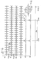
- FIG. 2 shows the timing diagrams of the transmission signals S1, S2 transmitted by the transmitting-receiving stations 1, 2, the received signals E1, E2 received by the transmitting-receiving stations 1, 2, the intermediate-frequency signal Z1, Z2, and the evaluation signals D1, D2 for the case that transceiver stations 1, 2 are located in the same place.
- ⁇ 0, d. H.
- the transmission signals S1, S2 are not delayed on the transmission path. Therefore, the first transmission signal S1 corresponds to the second reception signal E2 and the second transmission signal S2 corresponds to the first reception signal E1.
- the envelopes of the signals S1, S2, E1, E2 are shown. These represent pulses which, in the case of the first transmission signal S1 and the second reception signal E2, are spaced from each other by one pulse period Tp1 and are spaced apart by one pulse period Tp2 in the case of the second transmission signal S2 and the first reception signal E1.
- the pulse periods Tp1, Tp2 correspond to the reciprocal of the pulse repetition frequency fp1 or fp2 of the respective signal.
- the mixture in the mixers 14, 15 corresponds to a sampling of the first and second received signals E1, E2 with the first and second transmit signals S1 and S2, respectively.
- the difference frequency value fd is set so low that it is a sub-sample.
- the resulting evaluation signals D1, D2 are also pulse-shaped signals whose pulses occur periodically in the pulse interval Td.
- Td 1 / fd, where fd represents the difference frequency value by which the pulse repetition frequencies fp1, fp2 differ from one another.
- the pulses of the first evaluation signal D1 occur at times at which pulses of the first transmission signal S1 and the first reception signal E1 coincide. These times are referred to as first coincidence points in the following.
- the pulses of the second evaluation signal D2 occur at times at which pulses of the second transmission signal S2 and the second Receive signal E2 meet. These times are referred to below as the second coincidence times.
- time points t01, t02 are still shown, to which the pulses of the two transmission signals S1, S2 coincide in time. These time points, which are also spaced apart from one another by the pulse interval Td, are referred to below as transmit coincidence times.
- FIG. 3 shows the signals from FIG. 2 in the event that the first received signal E1 is delayed in time relative to the second transmitting signal S2 and the second receiving signal E2 is delayed in time by the signal propagation time ⁇ > 0 in relation to the first transmitting signal S1.
- the evaluation signals D1 and D2 then move relative to the transmission coincidence times t01, t02 in different directions. The direction of the shift depends on whether the first transmission signal S1 has the higher or lower pulse repetition frequency compared to the second transmission signal S2.
- the first evaluation signal D1 is shifted to the right relative to the transmission coincidence times t01, t02 by a first shift value tv1, while the second evaluation signal D2 is shifted to the left by a second shift value tv2.
- ⁇ stands for the signal propagation time
- fp1 and fp2 represent the pulse repetition frequency of the first and second transmit signals S1 and S2, respectively
- fd stands for the difference frequency value.
- na1, na2 are referred to below as expansion factors.
- the signal propagation time ⁇ and thus also the distance between the transceiver stations 1 and 2 can now be determined by measuring the coincidence distance tm.
- the measurement of the signal propagation time ⁇ of the transmission signals S1, S2 from an original time domain can be traced back to a time base of several orders of magnitude greater than the signal propagation time ⁇ in an imaging time range of the evaluation signals D1, D2.
- the measurement of times of the order of a few ns in the original time range can be attributed to a measurement of times on the order of a few ⁇ s or even ms in the imaging time range, which involves little technical effort. It is thus with little effort possible to measure distances with a spatial resolution of about 10 cm, which corresponds to a time resolution of about 300 ps in the original time range.
- both the first coincidence times t11, t12 and the second coincidence times t21, t22 must be known or determined at the location of the first transmission point tm at this location.
- Receiving station 1 sizes are provided, which are in a certain relationship to the coincidence times t21, t22.
- information about the second coincidence times t21, t22 is transmitted via a separate radio channel from the second transceiver station 2 to the first transceiver station 1, ie. H. via a radio channel whose carrier frequency differs from the carrier frequency of the first and second transmission signals S1, S2.
- the carrier frequency of the separate radio channel is advantageously lower than the carrier frequency of the transmission signals S1, S2.
- the signal delay ⁇ can also be determined by modulating the second transmission signal S2 and the modulation-resulting change in the distance between the first coincidence times t11, t12,... D. H. the pulse interval between the pulses of the first Aus sectionnals D1, as set out below, is evaluated, or by the first transmission signal S1 is modulated and resulting from the modulation change in the distance between the second coincidence times t21, t22, ... d. H. the pulse interval between the pulses of the second evaluation signal D2 is evaluated.
- Figure 4 shows the signals of Figures 2 and 3 for the case that the second transmission signal S2 is modulated by frequency shift keying the pulse repetition frequency fp2.
- the pulses of the signals are now represented only by dashes, which mark the times of occurrence of the pulses.
- the frequency shift keying takes place synchronously with the pulses of the second evaluation signal D2.
- the pulse repetition frequency fp2 is switched to the coincidence times t22, t24.
- the pulse repetition frequency fp2 is then equal to the first frequency value f21 and in the time interval B is equal to the second frequency value f22.
- the frequency jump around the frequency step .DELTA.f has the consequence that the pulse interval Td between the pulses of the second evaluation signal D2 is reduced from the value m to the value n by the frequency shift keying, or is increased again from the value n to the value m.
- the value m is therefore twice as large as the value n.
- Frequency shift keying also has the result that, when the pulse repetition frequency fp2 is up-sampled to the second fixed frequency value f22, the pulse interval Td between the pulses of the first evaluation signal D1 and the value m is reduced to a value x by a distance-proportional time td. Accordingly, in the back-sampling of the pulse repetition frequency fp2 to the first fixed frequency value f21 and that due to the increase of the pulse interval Td between the pulses of the second evaluation signal D2, the pulse interval Td between the pulses of the first Ausepticnals D1 of value n by the distance-proportional time td increases to a value y.
- the values x and y are thus linearly dependent on the signal propagation time ⁇ .
- the described method also enables a transmission of data from the second transceiver station 2 to the first transceiver station 1. For this purpose, it is only necessary to assign one of the logical values to the values m and n Assign "0" or "1". The value x is then to be assigned the logical value of the value m and the value y the logical value of the value n. In the same way, data can also be transmitted from the first transceiver station 1 to the second transceiver station 2 by frequency shift keying.
- the frequency step .DELTA.f does not change the pulse interval Td between the pulses of the evaluation signals D1, D2.
- FIGS. 6a and 6b show the same signals for a signal delay time ⁇ > 0.
- the frequency change from the frequency value f21 to Frequency value f22 occurs at time t21 and the frequency change from frequency value f22 back to frequency value f21 at time t24, ie synchronously with the pulses of second evaluation signal D2.
- the frequency change causes no change in the amount of coincidence distance tm, it only changes the direction of the offset hiss the evaluation signals D1, D2, d. H. the sign of the phase difference between these signals.
- the change in the pulse interval between the pulses of the first evaluation signal D1 resulting from the frequency shift keying is thus dependent on the signal delay time ⁇ .
- This type of frequency shift keying is particularly well suited for the serial transmission of digital data.
- a digital data signal Dx is transmitted from the second transceiver station 2 to the first transceiver station 1 by transmitting the pulse repetition frequency fp2 of the second transmission signal S2 in time domains A in which a logic value "0" is to be transmitted , to the first frequency value f21 and in time ranges B, in which a logical "1" is to be transmitted, is set to the second frequency value f22.
- the first transceiver station 1 it is then possible, on the basis of the pulse interval between the pulses of the first evaluation signal D1, to detect whether a bit value change has taken place in the data signal Dx.
- the pulse interval is shortened to a value U lying below the period Td, this is an indication of a bit value change from "0" to "1"
- the pulse interval is extended to a value lying above the period Td. This is an indication of a bit value change from "1" to "0”.
- the first transmission signal S1 by Frequenzumtastung be modulated, whereby a bidirectional data transmission between the transmitting-receiving station 1, 2 is ensured.
- the described methods provide unique measurement results only for signal propagation times ⁇ which lie within a uniqueness range determined by the pulse repetition frequencies fp1, fp2. Although the uniqueness range can be increased by changing the pulse repetition frequencies fp1, fp2, for example by frequency division, this is associated with a reduction in the measurement resolution.
- Exceeding the uniqueness range during a measurement can be detected by an additional measurement by increasing the uniqueness range for the additional measurement by changing the pulse repetition frequencies fp1, fp2 and by checking whether the result of the additional measurement is within the uniqueness range of the one measurement.
Landscapes
- Engineering & Computer Science (AREA)
- Radar, Positioning & Navigation (AREA)
- Remote Sensing (AREA)
- Computer Networks & Wireless Communication (AREA)
- Physics & Mathematics (AREA)
- General Physics & Mathematics (AREA)
- Radar Systems Or Details Thereof (AREA)
- Lock And Its Accessories (AREA)
Claims (12)
- Procédé de détermination de l'intervalle entre une première et une deuxième station d'émission-réception (1, 2), caractérisé en ce que- dans la première et la deuxième stations d'émission-réception (1, 2), un premier ou un deuxième signal d'émission (S1, S2) est produit et, en tant que série d'impulsions hyperfréquences avec une fréquence de répétition d'impulsions (fp1, fp2) prédéfinie, envoyé à l'autre station d'émission-réception (2, 1) respective, et est reçu par celle-ci en tant que signal de réception (E2, E1), les fréquences de répétition d'impulsions (fp1, fp2) des signaux d'émission (S1, S2) se distinguant les unes des autres selon une valeur de fréquence différentielle (fd) prédéfinie,- en ce que, dans la première et la deuxième stations d'émission-réception (1, 2), des premiers ou deuxièmes moments de coïncidence (t11, t12, ... ; t21, t22, ...) sont déterminés, qui correspondent aux moments où des impulsions du signal d'émission (S1, S2) émis par la station d'émission-réception (1, 2) respective et du signal de réception (E1, E2) reçu coïncident,- en ce que l'intervalle entre les stations d'émission-réception (1, 2) est déterminé à partir des intervalles (tm ; x, y ; U, D) entre les moments de coïncidence.
- Procédé selon la revendication 1, caractérisé en ce qu'un intervalle de coïncidence (tm) correspondant au décalage temporel entre les premiers et deuxièmes moments de coïncidence est déterminé en tant que mesure de l'intervalle entre les deux stations d'émission-réception (1, 2).
- Procédé selon la revendication 2, caractérisé en ce que des informations sur les deuxièmes moments de coïncidence (t21, t22) sont transmises, via une liaison radioélectrique, de la deuxième station d'émission-réception (2) vers la première station d'émission-réception (1), et en ce que l'intervalle de coïncidence (tm) dans la première station d'émission-réception (1) est déterminé à partir des informations transmises et des premiers moments de coïncidence (t11, t12) déterminés dans la première station d'émission-réception (1).
- Procédé selon la revendication 3, caractérisé en ce que la transmission des informations sur les deuxièmes moments de coïncidence (t21, t22) et la transmission des signaux d'émission (S1, S2) s'effectuent via des liaisons radioélectriques différentes.
- Procédé selon la revendication 1, caractérisé en ce que le deuxième signal d'émission (S2) est modulé par modulation par déplacement de fréquence de sa fréquence de répétition d'impulsions (fp2), et en ce qu'une variation (td), résultant de la modulation par déplacement de fréquence, de l'intervalle (Td) entre les premiers moments de coïncidence (t11, t12, ...) est déterminée en tant que mesure de l'intervalle entre les stations d'émission-réception (1, 2).
- Procédé selon la revendication 5, caractérisé en ce que la fréquence de répétition d'impulsions (fp2) du deuxième signal d'émission (S2) est commutée lors de la modulation par déplacement de fréquence entre deux valeurs de fréquence (f21, f22), la commutation s'effectuant de façon synchrone avec les deuxièmes moments de coïncidence (t21, t22,...).
- Procédé selon la revendication 6, caractérisé en ce que les deux valeurs de fréquence (f21, f22) fixes sont prédéfinies de sorte que le changement depuis une valeur de fréquence (f21) vers l'autre valeur de fréquence (f22) provoque un doublement de la valeur de la différence entre les fréquences de répétition d'impulsions (fp1, fp2) des signaux d'émission (S1, S2).
- Procédé selon la revendication 6, caractérisé en ce que les deux valeurs de fréquence (f21, f22) fixes sont prédéfinies de sorte que le changement depuis une valeur de fréquence (f21) vers l'autre valeur de fréquence (f22) provoque une inversion de la différence entre les fréquences de répétition d'impulsions (fp1, fp2) des signaux d'émission (S1, S2).
- Procédé selon une des revendications précédentes; caractérisé en ce que la valeur de fréquence différentielle (fd) est beaucoup plus faible que les fréquences de répétition d'impulsions (fp1, fp2).
- Procédé selon une des revendications précédentes, caractérisé en ce que les deux signaux d'émission (S1, S2) sont modulés pour la transmission de données.
- Procédé selon une des revendications précédentes, caractérisé en ce que, dans les stations d'émission-réception (1, 2), le signal d'émission (S1, S2) produit dans la station d'émission-réception (1, 2) respective est converti avec le signal de réception (E1, E2) reçu par cette station, par mélange, en un signal de fréquence intermédiaire (Z1, Z2), en ce que le signal de fréquence intermédiaire (Z1, Z2) est converti, par filtrage et démodulation de courbes enveloppantes, en un signal d'analyse (D1, D2) en forme d'impulsions, et en ce que la position temporelle des impulsions du signal d'analyse (D1, D2) est déterminée en tant que moments de coïncidence (t11, t12, t21, t22).
- Utilisation du procédé selon une des revendications précédentes dans un système de fermeture sans clé pour véhicules automobiles en vue de la détermination de l'intervalle entre une première station d'émission-réception prévue dans le véhicule automobile et une deuxième station d'émission-réception prévue dans un module de clé.
Applications Claiming Priority (3)
| Application Number | Priority Date | Filing Date | Title |
|---|---|---|---|
| DE10247718 | 2002-10-12 | ||
| DE10247718A DE10247718A1 (de) | 2002-10-12 | 2002-10-12 | Verfahren zur Ermittlung des Abstands zwischen einer ersten und zweiten Sende-Empfangs-Station |
| PCT/DE2003/002967 WO2004035357A2 (fr) | 2002-10-12 | 2003-09-08 | Procede de determination de la distance entre deux stations emettrices-receptrices et stations emettrices-receptrices correspondantes |
Publications (2)
| Publication Number | Publication Date |
|---|---|
| EP1556259A2 EP1556259A2 (fr) | 2005-07-27 |
| EP1556259B1 true EP1556259B1 (fr) | 2006-06-21 |
Family
ID=32038600
Family Applications (1)
| Application Number | Title | Priority Date | Filing Date |
|---|---|---|---|
| EP03757658A Expired - Lifetime EP1556259B1 (fr) | 2002-10-12 | 2003-09-08 | Procede de determination de la distance entre deux stations emettrices-receptrices et stations emettrices-receptrices correspondantes |
Country Status (5)
| Country | Link |
|---|---|
| US (1) | US20060013166A1 (fr) |
| EP (1) | EP1556259B1 (fr) |
| JP (1) | JP2006510001A (fr) |
| DE (2) | DE10247718A1 (fr) |
| WO (1) | WO2004035357A2 (fr) |
Families Citing this family (10)
| Publication number | Priority date | Publication date | Assignee | Title |
|---|---|---|---|---|
| JP4853993B2 (ja) * | 2005-03-11 | 2012-01-11 | 独立行政法人情報通信研究機構 | 測距システム |
| DE102008025244A1 (de) * | 2008-05-27 | 2009-12-03 | Siemens Aktiengesellschaft | Verfahren zur funkbasierten Abstandmessung |
| JP5173623B2 (ja) * | 2008-06-19 | 2013-04-03 | パナソニック株式会社 | 無線測距システム及び無線測距方法 |
| EP2196823B1 (fr) * | 2008-12-12 | 2011-06-15 | Lambda: 4 Entwicklungen GmbH | Procédé de détermination de la distance entre deux objets |
| DE102009036937A1 (de) * | 2009-08-11 | 2011-02-17 | Siemens Aktiengesellschaft | Verfahren und Anordnung zur Laufzeitmessung eines Signals zwischen zwei Stationen der Anordnung |
| DE102009050796B4 (de) * | 2009-10-27 | 2015-06-18 | Siemens Aktiengesellschaft | Verfahren und Anordnung zur Messung der Signallaufzeit zwischen einem Sender und einem Empfänger |
| EP3187893B1 (fr) | 2011-05-18 | 2022-07-06 | Lambda: 4 Entwicklungen GmbH | Procédé de détermination de l'emplacement d'un récepteur |
| DE102011083597A1 (de) * | 2011-09-28 | 2013-03-28 | Siemens Aktiengesellschaft | Verfahren und Vorrichtung zur Abstandsbestimmung zwischen Kommunikationseinrichtungen |
| JP5522554B2 (ja) * | 2013-05-01 | 2014-06-18 | 株式会社デンソー | 制御システム |
| US11533076B1 (en) * | 2021-09-30 | 2022-12-20 | Shenzhen GOODIX Technology Co., Ltd. | Phase based distance estimation with non-zero intermediate frequency |
Family Cites Families (16)
| Publication number | Priority date | Publication date | Assignee | Title |
|---|---|---|---|---|
| US3117317A (en) * | 1959-05-25 | 1964-01-07 | Sperry Rand Corp | Distance measuring circuit |
| CH519177A (de) * | 1971-01-22 | 1972-02-15 | Siemens Ag Albis | Verfahren und Schaltungsanordnung zur Entfernungsmessung |
| EP0834749B1 (fr) * | 1996-10-05 | 1999-06-23 | Oerlikon Contraves Ag | Système et dispositif de télémétrie entre deux stations reliées par un canal de communication |
| BR9913440B1 (pt) * | 1998-09-01 | 2008-11-18 | processo para a realizaÇço de um controle de autorizaÇço de acesso sem chave e equipamento de controle de autorizaÇço de acesso sem chave. | |
| US6389264B1 (en) * | 1999-02-17 | 2002-05-14 | Nokia Telecommunications Oy | Distance measurement system for timing advance controlled systems |
| DE19909140A1 (de) * | 1999-03-03 | 2000-09-21 | Daimler Chrysler Ag | Elektronische Entfernungsbestimmungsvorrichtung und damit ausgerüstete elektronische Sicherungsanlage |
| JP3970467B2 (ja) * | 1999-03-18 | 2007-09-05 | 富士通株式会社 | 無線通信システム |
| JP3411856B2 (ja) * | 1999-07-26 | 2003-06-03 | 松下電器産業株式会社 | 距離検出方法及び距離検出装置 |
| DE10019277A1 (de) * | 2000-04-19 | 2001-11-22 | Daimler Chrysler Ag | Sicherungsverfahren und Abfrageeinheit sowie Sicherungssystem zur Durchführung des Sicherungsverfahren |
| US6993098B2 (en) * | 2001-07-12 | 2006-01-31 | Koninklijke Philips Electronics N.V. | Method and apparatus for efficient calculating distance metric |
| US7146433B2 (en) * | 2002-02-01 | 2006-12-05 | Lenovo Singapore Pte. Ltd | Extending an allowable transmission distance between a wireless device and an access point by communication with intermediate wireless devices |
| DE10247719A1 (de) * | 2002-10-12 | 2004-04-22 | Conti Temic Microelectronic Gmbh | Verfahren zur Ermittlung des Abstands zwischen zwei Sende-Empfangs-Stationen und Sende-Empfangs-Stationen zur Durchführung des Verfahrens |
| WO2004077711A2 (fr) * | 2003-02-24 | 2004-09-10 | Hawe William R | Systeme, procede et appareil de determination d'un attribut dynamique d'un systeme |
| US20050058081A1 (en) * | 2003-09-16 | 2005-03-17 | Elliott Brig Barnum | Systems and methods for measuring the distance between devices |
| JP4443939B2 (ja) * | 2004-01-13 | 2010-03-31 | 日本信号株式会社 | 受信時刻計測装置及びこれを用いた距離計測装置 |
| KR100577682B1 (ko) * | 2004-06-04 | 2006-05-10 | 삼성전자주식회사 | 노드들로 구성된 통신 시스템에서 거리 추정 장치 및 방법 |
-
2002
- 2002-10-12 DE DE10247718A patent/DE10247718A1/de not_active Withdrawn
-
2003
- 2003-09-08 WO PCT/DE2003/002967 patent/WO2004035357A2/fr not_active Ceased
- 2003-09-08 EP EP03757658A patent/EP1556259B1/fr not_active Expired - Lifetime
- 2003-09-08 US US10/530,913 patent/US20060013166A1/en not_active Abandoned
- 2003-09-08 JP JP2004543936A patent/JP2006510001A/ja not_active Ceased
- 2003-09-08 DE DE50303991T patent/DE50303991D1/de not_active Expired - Lifetime
Also Published As
| Publication number | Publication date |
|---|---|
| US20060013166A1 (en) | 2006-01-19 |
| JP2006510001A (ja) | 2006-03-23 |
| DE50303991D1 (de) | 2006-08-03 |
| EP1556259A2 (fr) | 2005-07-27 |
| WO2004035357A3 (fr) | 2005-05-26 |
| WO2004035357A2 (fr) | 2004-04-29 |
| DE10247718A1 (de) | 2004-04-22 |
Similar Documents
| Publication | Publication Date | Title |
|---|---|---|
| DE2524571C3 (de) | Homodyn-Übertragungssystem mit Phasendetektor zur Funkortung | |
| DE2410500C3 (de) | Pulsradarsystem linear zeitverknüpfter Tragerfrequenz mit hohem Entfernungsauflösungsvermögen | |
| EP0727051B1 (fr) | Radar et procede permettant de le faire fonctionner | |
| EP1109981B1 (fr) | Procede pour effectuer un controle d'autorisation d'acces sans cle, et unite de controle d'autorisation d'acces sans cle | |
| DE69020203T2 (de) | Verfahren und Gerät zur Hilfe des Landfahrzeugverkehrs. | |
| EP1466189B1 (fr) | Procede servant a determiner la distance entre une station de base et un objet mobile, et station de base et systeme d'identification connus pour ce procede | |
| EP2483706B1 (fr) | Détecteur radar à deux oscillateurs, à deux mélangeurs d'émission i/q, et à deux mélangeurs de réception i/q | |
| DE19957536C2 (de) | Diebstahlschutzsystem für ein Kraftfahrzeug und Verfahren zum Betreiben eines Diebstahlschutzsystems | |
| EP2126603B1 (fr) | Procédé pour radar FMCW avec évaluation de la phase des signaux différentiels | |
| DE19922411A1 (de) | Radarverfahren zur Messung von Abständen und Relativgeschwindigkeiten zwischen einem Fahrzeug und einem oder mehreren Hindernissen | |
| DE2839643A1 (de) | Radarsystem fuer kraftfahrzeuge | |
| EP1556259B1 (fr) | Procede de determination de la distance entre deux stations emettrices-receptrices et stations emettrices-receptrices correspondantes | |
| EP0519361B1 (fr) | Dispositif de radar à onde continue, usable additionellement comme transmetteur d'informations | |
| DE69922428T2 (de) | Dauerstrichradar-Empfänger mit Frequenzsprung | |
| EP1549971B1 (fr) | Procede de determination de la distance entre deux stations emettrices-receptrices | |
| DE19839695C1 (de) | Verfahren zum Durchführen einer schlüssellosen Zugangsberechtigungskontrolle sowie schlüssellose Zugangsberechtigungskontrolleinrichtung | |
| EP1549972B1 (fr) | Procede de determination de la distance entre deux stations emettrices-receptrices et stations emettrices-receptrices correspondantes | |
| DE102004038836A1 (de) | Verfahren zur Entfernungsmessung in einem drahtlosen Trägerfrequenz-Kommunikationssystem und Trägerfrequenz-Kommunikationssystem zur Durchführung des Verfahrens | |
| DE4035501A1 (de) | Verfahren zur bestimmung der relativen position von fahrzeugen im strassenverkehr | |
| DE3118852A1 (de) | "rundfunkempfaenger" | |
| DE10013913B4 (de) | Verfahren und System zur Bestimmung der Entfernung eines Handmoduls von einem Einrichtungsmodul | |
| DE1155828B (de) | UEber einen vorgegebenen Frequenzbereich abstimmbare drahtlose Sende-Empfangs-Station | |
| WO2011000605A1 (fr) | Contrôle d'un mélangeur | |
| EP0717517A2 (fr) | Méthode et dispositif pour l'évaluation d'un signal RDS | |
| DE69009573T2 (de) | Einrichtung zur Detektion der Durchfahrt von mindestens einem beweglichen Gegenstand an mindestens einem bestimmten Punkt seiner Bewegung. |
Legal Events
| Date | Code | Title | Description |
|---|---|---|---|
| PUAI | Public reference made under article 153(3) epc to a published international application that has entered the european phase |
Free format text: ORIGINAL CODE: 0009012 |
|
| 17P | Request for examination filed |
Effective date: 20050209 |
|
| AK | Designated contracting states |
Kind code of ref document: A2 Designated state(s): AT BE BG CH CY CZ DE DK EE ES FI FR GB GR HU IE IT LI LU MC NL PT RO SE SI SK TR |
|
| GRAP | Despatch of communication of intention to grant a patent |
Free format text: ORIGINAL CODE: EPIDOSNIGR1 |
|
| RBV | Designated contracting states (corrected) |
Designated state(s): DE FR |
|
| GRAS | Grant fee paid |
Free format text: ORIGINAL CODE: EPIDOSNIGR3 |
|
| GRAA | (expected) grant |
Free format text: ORIGINAL CODE: 0009210 |
|
| AK | Designated contracting states |
Kind code of ref document: B1 Designated state(s): DE FR |
|
| REF | Corresponds to: |
Ref document number: 50303991 Country of ref document: DE Date of ref document: 20060803 Kind code of ref document: P |
|
| ET | Fr: translation filed | ||
| PLBE | No opposition filed within time limit |
Free format text: ORIGINAL CODE: 0009261 |
|
| STAA | Information on the status of an ep patent application or granted ep patent |
Free format text: STATUS: NO OPPOSITION FILED WITHIN TIME LIMIT |
|
| 26N | No opposition filed |
Effective date: 20070322 |
|
| PGFP | Annual fee paid to national office [announced via postgrant information from national office to epo] |
Ref country code: FR Payment date: 20080912 Year of fee payment: 6 |
|
| REG | Reference to a national code |
Ref country code: FR Ref legal event code: ST Effective date: 20100531 |
|
| PG25 | Lapsed in a contracting state [announced via postgrant information from national office to epo] |
Ref country code: FR Free format text: LAPSE BECAUSE OF NON-PAYMENT OF DUE FEES Effective date: 20090930 |
|
| PGFP | Annual fee paid to national office [announced via postgrant information from national office to epo] |
Ref country code: DE Payment date: 20180930 Year of fee payment: 16 |
|
| REG | Reference to a national code |
Ref country code: DE Ref legal event code: R119 Ref document number: 50303991 Country of ref document: DE |
|
| PG25 | Lapsed in a contracting state [announced via postgrant information from national office to epo] |
Ref country code: DE Free format text: LAPSE BECAUSE OF NON-PAYMENT OF DUE FEES Effective date: 20200401 |