EP1550548A1 - Systeme de laminage - Google Patents
Systeme de laminage Download PDFInfo
- Publication number
- EP1550548A1 EP1550548A1 EP02807899A EP02807899A EP1550548A1 EP 1550548 A1 EP1550548 A1 EP 1550548A1 EP 02807899 A EP02807899 A EP 02807899A EP 02807899 A EP02807899 A EP 02807899A EP 1550548 A1 EP1550548 A1 EP 1550548A1
- Authority
- EP
- European Patent Office
- Prior art keywords
- weight
- parts
- laminated
- diaphragm
- laminating apparatus
- Prior art date
- Legal status (The legal status is an assumption and is not a legal conclusion. Google has not performed a legal analysis and makes no representation as to the accuracy of the status listed.)
- Withdrawn
Links
Images



Classifications
-
- B—PERFORMING OPERATIONS; TRANSPORTING
- B32—LAYERED PRODUCTS
- B32B—LAYERED PRODUCTS, i.e. PRODUCTS BUILT-UP OF STRATA OF FLAT OR NON-FLAT, e.g. CELLULAR OR HONEYCOMB, FORM
- B32B37/00—Methods or apparatus for laminating, e.g. by curing or by ultrasonic bonding
- B32B37/10—Methods or apparatus for laminating, e.g. by curing or by ultrasonic bonding characterised by the pressing technique, e.g. using action of vacuum or fluid pressure
- B32B37/1009—Methods or apparatus for laminating, e.g. by curing or by ultrasonic bonding characterised by the pressing technique, e.g. using action of vacuum or fluid pressure using vacuum and fluid pressure
-
- B—PERFORMING OPERATIONS; TRANSPORTING
- B30—PRESSES
- B30B—PRESSES IN GENERAL
- B30B5/00—Presses characterised by the use of pressing means other than those mentioned in the preceding groups
- B30B5/02—Presses characterised by the use of pressing means other than those mentioned in the preceding groups wherein the pressing means is in the form of a flexible element, e.g. diaphragm, urged by fluid pressure
-
- B—PERFORMING OPERATIONS; TRANSPORTING
- B32—LAYERED PRODUCTS
- B32B—LAYERED PRODUCTS, i.e. PRODUCTS BUILT-UP OF STRATA OF FLAT OR NON-FLAT, e.g. CELLULAR OR HONEYCOMB, FORM
- B32B37/00—Methods or apparatus for laminating, e.g. by curing or by ultrasonic bonding
- B32B37/10—Methods or apparatus for laminating, e.g. by curing or by ultrasonic bonding characterised by the pressing technique, e.g. using action of vacuum or fluid pressure
-
- B—PERFORMING OPERATIONS; TRANSPORTING
- B32—LAYERED PRODUCTS
- B32B—LAYERED PRODUCTS, i.e. PRODUCTS BUILT-UP OF STRATA OF FLAT OR NON-FLAT, e.g. CELLULAR OR HONEYCOMB, FORM
- B32B2457/00—Electrical equipment
- B32B2457/12—Photovoltaic modules
Definitions
- the present invention relates to a laminating apparatus for producing a laminated object such as a solar battery panel.
- a laminating apparatus for producing a solar battery panel a laminating apparatus of so-called double vacuum system is publicly known, which has an upper chamber and a lower chamber partitioned by a diaphragm.
- a laminating apparatus of double vacuum system there are disclosed Japanese Patent Publication No. Hei 4-65556 "Solar Battery Module Laminating Apparatus” and Japanese Patent Publication No. Hei 6-52801 "Method of Producing Solar Battery Panel.”
- a diaphragm is pressurized downward in a state that an object to be laminated mounted on a heater board is heated, thereby pressurizing the object to be laminated from top and bottom between the heater board and the diaphragm.
- a silicon resin film is generally used as the diaphragm for pressurizing the object to be laminated.
- the diaphragm constituted of conventional silicon resin film has a problem of having low heat resistance property and poor elastic performance.
- the diaphragm when laminating a solar battery panel, the diaphragm is heated to a temperature of approximately 180°C, but in such a case, the diaphragm constituted of silicon resin would get damaged after performing about 3000 times of laminating processes.
- the diaphragm constituted of silicon resin when performing about 300 times of laminating processes in a day, the diaphragm constituted of silicon resin has a lifetime of only about ten days.
- the diaphragm constituted of silicon resin is expensive, and thus frequent replacement of which causes a cost related problem.
- an object of the present invention is to obtain a laminating apparatus having a diaphragm with a long lifetime.
- the present invention provides a laminating apparatus for laminating an object to be laminated, which includes an upper chamber and a lower chamber which are partitioned by a diaphragm, a heater board provided in the lower chamber, and a diaphragm capable of freely expanding for pressurizing the object to be laminated mounted on the heater board, in which the diaphragm is constituted of butyl rubber.
- the composition of the butyl rubber includes 100 to 0 parts by weight of halogenated butyl, 0 to 100 parts by weight of regular butyl, 1 to 5 parts by weight of magnesium oxide, 5 to 100 parts by weight of carbon black, 0 to 20 parts by weight of paraffin oil, 1 to 5 parts by weight of zinc oxide, 1 to 20 parts by weight of resin vulcanizing agent, and 0 to 10 parts by weight of processing aid.
- a holding means for holding the object to be laminated mounted on the heater board in a state that the object to be laminated is separated upward from an upper surface of the heater board while the object to be laminated is carried in.
- the holding means may be configured to hold the object to be laminated in a state that the object to be laminated is separated upward from the upper surface of the heater board also while the object to be laminated is carried out.
- the object to be laminated is a solar battery panel for example.
- FIG. 1 is a front view of a laminating apparatus 1 according to an example of the present invention
- FIG. 2 is a plan view of the laminating apparatus 1.
- the laminating apparatus 1 shown in the views has an upper case 2 and a lower case 3. These upper case 2 and lower case 3 are joined together via a hinge part 4 arranged on the rear side thereof, and the upper case 2 is pivoted upward about the hinge part 4 so as to open the laminating apparatus 1.
- an air cylinder or the like to lift the upper case 2 for facilitating opening may be provided.
- a loader conveyor 6 for mounting a solar battery panel a as an object to be laminated before being laminated by the laminating apparatus 1 and an unloader conveyor 7 for mounting a solar battery panel a after being laminated by the laminating apparatus 1 are arranged respectively.
- These loader conveyor 6 and unloader conveyor 7 are both configured to be raised and lowered.
- FIG. 1 shows the loader conveyor 6 in a raised state and the unloader conveyor 7 in a lowered state.
- traversers 30, 31 are arranged respectively for supporting sides of the solar battery panel a when these loader conveyor 6 and under conveyor 7 are lowered.
- the height of top surfaces of these traversers 30, 31 is set to a position lower than top surfaces of the loader conveyor 6 and the unloader conveyor 7 when these are raised, and to a position higher than the top surfaces of the loader conveyor 6 and the unloader conveyor 7 when these are lowered.
- the traverser 30 is configured to reciprocate between a position shown by solid lines 30 and a position shown by chain lines 30' in FIG. 1 and FIG. 2.
- the traverser 31 is configured to reciprocate between a position shown by solid lines 31 and a position shown by chain lines 31' in FIG. 1 and FIG. 2 (the positions shown by the chain lines 30' and the chain lines 31' are the same).
- the traverser 30 moves leftward to carry the solar battery panel a in a position between the upper case 2 and the lower case 3. Further, after receiving the solar battery panel a in the position between the upper case 2 and the lower case 3, the traverser 31 moves leftward to carry the solar battery panel a out to a position for passing the solar battery panel a to the unloader conveyor 7.
- casters 8 are attached to an under surface of the lower case 3, and the casters 8 are rolled to allow movement of the laminating apparatus 1 on a floor surface 9 with a small force.
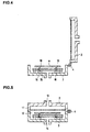
- FIG. 3 is a view showing an A-A cross section in FIG. 2 of a main part of the laminating apparatus 1 on an enlarged scale.
- a diaphragm 10 is fitted inside the upper case 2.
- This diaphragm 10 is constituted of butyl rubber.
- the composition of the butyl rubber used for the diaphragm 10 includes 100 to 0 parts by weight of halogenated butyl, 0 to 100 parts by weight of regular butyl, 1 to 5 parts by weight of magnesium oxide, 5 to 100 parts by weight of carbon black, 0 to 20 parts by weight of paraffin oil, 1 to 5 parts by weight of zinc oxide, 1 to 20 parts by weight of resin vulcanizing agent, and 0 to 10 parts by weight of processing aid.
- an upper chamber 11 and a lower chamber 12 which are partitioned into an upper side and a lower side by the diaphragm 10, are formed inside the laminating apparatus 1.
- inlet/outlet ports 13, 14 are provided on a top surface of the upper case 2 and an under surface of the lower case 3.
- the inside of the upper chamber 11 and the inside of the lower chamber 12 can be evacuated via the inlet/outlet ports 13, 14 respectively, and also atmospheric pressure can be introduced into the upper chamber 11 and the lower chamber 12 via the inlet/outlet ports 13, 14 respectively.
- a heater board 15 is provided inside the lower case 3. This heater board 15 is fixed at a certain height by support posts 16 formed to project on a bottom surface of the lower case 3, and the height of a top surface of the heater board 15 is set to a position lower than the height of the top surfaces of the previously described traversers 30, 31.
- the heater board 15 is constituted of, for example, a sheathed heater made of aluminum, and in addition, the heater board 15 may have a water cooling pipe or the like for performing accurate temperature control.
- the holding means 17 are each constituted of a raising/lowering mechanism 18 and a support pin 19.
- a publicly known raising/lowering means for example, an air cylinder, a ball nut, a rack and pinion, or the like, can be appropriately used, and by the operation of the raising/lowering mechanism 18, the support pin 19 can be raised and lowered.
- Through holes 20 are formed in the heater board 15, and the support pins 19 which are raised and lowered by the operation of the raising/lowering mechanisms 18 are arranged to penetrate these through holes 20.
- the support pins 19 are raised by the operation of the raising/lowering mechanisms 18, as shown by chain lines 19' in FIG. 3, upper ends of the support pins 19 project upward and higher than the upper surface of the heater board 15 via the through holes 20. Further, the height of the upper ends of the support pins 19 thus raised is set to a position higher than the height of the upper surfaces of the previously described traversers 30, 31.
- the support pins 19 are lowered by the operation of the raising/lowering mechanisms 18, the upper ends of the support pins 19 are lowered to approximately the same height as the upper surface of the heater board 15, as shown by solid lines 19 in FIG. 3.
- the solar battery panel a as an example of a laminated object produced by the laminating apparatus 1 of the present invention has a structure such that strings are sandwiched with a filler between a reinforcing material and a cover glass.
- a reinforcing material for example, PE resin or the like are used.
- the filler for example, EVA (ethylene-vinyl acetate) resin or the like is used.
- the strings has a structure such that solar battery cells are connected between electrodes via lead wires.
- the operation of the laminating apparatus 1 will be described with the case of producing the solar battery panel a for example.
- the upper case 2 is pivoted upward about the hinge part 4 from the lower case 3 so that the upper chamber 11 is in an open state, and the support pins 19 are in a state being lowered in advance by the operation of the raising/lowering mechanisms 18.
- the loader conveyor 6 is in a raised state, and on the top surface thereof, the solar battery panels a as objects to be laminated are mounted.
- the unloader conveyor 7 is in a lowered state.
- the traversers 30, 31 are in a standby state at positions on the both sides of the loader conveyor 6 and the unloader conveyor 7 respectively.
- the loader conveyor 6 is lowered. Accordingly, the solar battery panels a, which have been mounted on the top surface of the loader conveyor 6 up to this point, are now in a state being supported by the traverser 30. Then, the traverser 30 moves to the position shown by the chain lines 30' in FIG. 1 and FIG. 2 so as to carry the solar battery panels a in the position between the upper case 2 and the lower case 3. Incidentally, after the solar battery panels a are carried in, the loader conveyor 6 is raised again, and onto the top surface thereof, next solar battery panels a will be carried in.
- the support pins 19 are raised by the operation of the raising/lowering mechanisms 18.
- the solar battery panels a are mounted on the upper ends of the support pins 19 projected upward and higher than the top surface of the heater board 15. Note that in this state, as shown in the view, the solar battery panels a are not in contact with the top surface of the heater board 15.
- the traverser 30 which passed the solar battery panels a then moves to return again to the position of both sides of the loader conveyor 6.
- the upper case 2 is pivoted downward about the hinge part 4 so as to cover the lower case 3 to thereby tightly close the laminating apparatus 1.
- the inside of the upper chamber 11 and the inside of the lower chamber 12 are then evacuated simultaneously via the inlet/outlet ports 13, 14.
- the support pins 19 are lowered by the operation of the raising/lowering mechanisms 18, as shown in FIG. 6.
- the solar battery panels a supported by the upper ends of the support pins 19 come in direct contact with the upper surface of the heater board 15, so that the solar battery panels a are heated.
- This heating facilitates chemical reaction of the EVA resin as fillers 23, 24 inside the solar battery panels a under a condition of vacuum state, and thus cross linkage takes place therein.
- the atmospheric pressure is introduced into the upper chamber 11 via the inlet/outlet port 13 to expand the diaphragm 10 downward, thereby sandwiching and pressurizing the solar battery panels a between the upper surface of the heater board 15 and the diaphragm 10.
- the atmospheric pressure is introduced into the lower chamber 12 via the inlet/outlet port 14. Further, the support pins 19 are raised by the operation of the raising/lowering mechanisms 18 to lift the solar battery panels a higher than the upper surface of the heater board 15.
- the upper case 2 is pivoted upward about the hinge part 4 from the lower case 3, so that the laminating apparatus 1 becomes an open state. Incidentally, lifting of this upper case 2 can be performed with a not-shown air cylinder or the like.
- the traverser 31 moves to the position shown by the chain lines 31' in FIG. 1 and FIG. 2 and enters the space under the solar battery panels a, which are lifted by the support pins 19. Thereafter, the support pins 19 are lowered by the operation of the raising/lowering mechanisms 18. Accordingly, the solar battery panels a supported by the upper ends of the support pins 19 are now in a state being supported by the traverser 31.
- the traverser 31 moves to return again to the position of both sides of the unloader conveyor 7 so as to remove the solar battery panels a from the position between the upper case 2 and the lower case 3. Thereafter, the unloader conveyor 7 is raised to receive the solar battery panels a on its upper surface, and appropriately carries them out. After the carrying out is completed, the unloader conveyor 7 is lowered again.
- the diaphragm 10 is constituted of butyl rubber, so that the lifetime of the diaphragm 10 becomes longer as compared with the case of using a diaphragm constituted of silicon resin, thereby reducing the labor of replacement. Further, laminated objects can be provided at a low cost.
- peroxide is generated from the EVA as a filler during lamination, but the butyl rubber barely react with the peroxide and hardly deteriorates.
- the silicon resin reacts with the peroxide and hardens, and is easy to break.
- the laminating apparatus of the present invention can perform laminating processes on various other objects.
- the laminating apparatus of the present invention can correspond to variation of thickness of an object to be laminated, and also can be used for producing integrated modules or the like, in which an outer wall material or a roofing material as a building material and a solar battery panel are integrated, which are gaining attention recently.
- the laminating apparatus of the present invention is not limited to the solar battery panel, which can be used for producing shatterproof glasses, ornament glasses, plywood, and the like.
- the composition of butyl rubber constituting the diaphragm includes 100 to 0 parts by weight of halogenated butyl, 0 to 100 parts by weight of regular butyl, 1 to 5 parts by weight of magnesium oxide, 5 to 100 parts by weight of carbon black, 0 to 20 parts by weight of paraffin oil, 1 to 5 parts by weight of zinc oxide, 1 to 20 parts by weight of resin vulcanizing agent, and 0 to 10 parts by weight of processing aid.
- the diaphragm constituted of this butyl rubber was obtained at approximately the same price as a conventionally used diaphragm constituted of silicon resin.
- the diaphragm constituted of butyl rubber did not harden even after repeating the lamination and became hard to break, and the diaphragm constituted of this butyl rubber endured approximately 6000 times of laminating processes and was capable of performing 300 times of laminating processes in a day for 20 days or more. As compared with the case of using the conventional diaphragm constituted of silicon resin, lifetime thereof became double or longer.
- a laminating apparatus having a diaphragm with a long lifetime can be provided. Further, laminated objects can be produced at a low cost.
Landscapes
- Physics & Mathematics (AREA)
- Fluid Mechanics (AREA)
- Engineering & Computer Science (AREA)
- Mechanical Engineering (AREA)
- Photovoltaic Devices (AREA)
- Press Drives And Press Lines (AREA)
- Lining Or Joining Of Plastics Or The Like (AREA)
Applications Claiming Priority (1)
| Application Number | Priority Date | Filing Date | Title |
|---|---|---|---|
| PCT/JP2002/010287 WO2004030900A1 (fr) | 2002-10-02 | 2002-10-02 | Systeme de laminage |
Publications (2)
| Publication Number | Publication Date |
|---|---|
| EP1550548A1 true EP1550548A1 (fr) | 2005-07-06 |
| EP1550548A4 EP1550548A4 (fr) | 2008-02-20 |
Family
ID=32051288
Family Applications (1)
| Application Number | Title | Priority Date | Filing Date |
|---|---|---|---|
| EP02807899A Withdrawn EP1550548A4 (fr) | 2002-10-02 | 2002-10-02 | Systeme de laminage |
Country Status (5)
| Country | Link |
|---|---|
| US (1) | US20060289119A1 (fr) |
| EP (1) | EP1550548A4 (fr) |
| JP (1) | JP4308769B2 (fr) |
| AU (1) | AU2002335176A1 (fr) |
| WO (1) | WO2004030900A1 (fr) |
Cited By (7)
| Publication number | Priority date | Publication date | Assignee | Title |
|---|---|---|---|---|
| EP1890339A1 (fr) * | 2006-08-18 | 2008-02-20 | NPC Incorporated | Appareil de laminage |
| EP1920922A2 (fr) | 2006-11-07 | 2008-05-14 | NPC Incorporated | Appareil de laminage |
| EP2065177A1 (fr) | 2007-11-30 | 2009-06-03 | komax Holding AG | Plaque chauffante dotée d'éléments de levage |
| EP2189284A2 (fr) | 2008-11-21 | 2010-05-26 | komax Holding AG | Dispositif de laminage d'un module solaire |
| US8028735B2 (en) * | 2006-11-16 | 2011-10-04 | Npc Incorporated | Laminating apparatus |
| DE102010061294A1 (de) * | 2010-12-16 | 2012-06-21 | Bayerische Motoren Werke Aktiengesellschaft | Laminierung von 3D-Solarbauteilen |
| CN110341233A (zh) * | 2019-07-23 | 2019-10-18 | 江西振态科技协同创新有限公司 | 防止热压机内导热油管内壁产生积碳的方法及装置 |
Families Citing this family (10)
| Publication number | Priority date | Publication date | Assignee | Title |
|---|---|---|---|---|
| US7768619B2 (en) * | 2004-08-03 | 2010-08-03 | Harris Corporation | Method and apparatus for sealing flex circuits made with an LCP substrate |
| KR101546099B1 (ko) * | 2009-10-07 | 2015-08-20 | 엘지전자 주식회사 | 라미네이팅 유니트 및 이를 포함한 라미네이팅 장치 |
| JP5129866B2 (ja) | 2010-02-25 | 2013-01-30 | 日清紡ホールディングス株式会社 | ダイアフラムシート |
| JP5554667B2 (ja) * | 2010-09-13 | 2014-07-23 | クレハエラストマー株式会社 | 太陽電池モジュール製造用ダイヤフラムおよびその評価方法ならびに太陽電池モジュールの製造方法 |
| KR101820564B1 (ko) | 2011-06-22 | 2018-01-19 | 구레하 엘라스토머 가부시키가이샤 | 태양전지 모듈 제조용 다이어프램 및 태양전지 모듈의 제조방법 |
| EP2584614A4 (fr) * | 2011-07-04 | 2014-11-19 | Nisshinbo Mechatronics Inc | Feuille de diaphragme, procédé de fabrication d'un module de cellule solaire à l'aide de la feuille de diaphragme, procédé de stratification utilisant un appareil de stratification pour la production d'un module de cellule solaire |
| US20140083609A1 (en) * | 2012-09-27 | 2014-03-27 | General Electric Company | Method and apparatus for evacuation of large composite structures |
| CZ304597B6 (cs) * | 2013-03-26 | 2014-07-23 | Univerzita Tomáše Bati ve Zlíně | Přítlačná membrána pro vakuové lisování dílců z polymerních kompozitů |
| JP6201913B2 (ja) * | 2014-06-27 | 2017-09-27 | 新東工業株式会社 | 加熱盤、加熱装置及び加熱方法 |
| KR102243574B1 (ko) * | 2020-07-03 | 2021-04-22 | 주식회사 가이아에너지 | 에너지 저감 라미네이팅 장치 |
Family Cites Families (13)
| Publication number | Priority date | Publication date | Assignee | Title |
|---|---|---|---|---|
| US24856A (en) * | 1859-07-26 | Machine for stoning- cherries | ||
| DE2026258A1 (de) * | 1970-05-29 | 1971-12-09 | Kalle Ag | Verfahren und Vorrichtung zur Her stellung eines Formatflachengebildes |
| US3857775A (en) * | 1972-05-09 | 1974-12-31 | Goodyear Tire & Rubber | Electrolytic cell including a flexible sheet covering the cell base |
| CA993597A (en) | 1972-10-23 | 1976-07-20 | Eric G. Kent | Vulcanization of bromobutyl |
| CA1217122A (fr) | 1983-06-01 | 1987-01-27 | John Timar | Nappe interne obturatrice de crevaisons pour pneus |
| JP2803144B2 (ja) * | 1989-04-13 | 1998-09-24 | エヌオーケー株式会社 | Pva系ラミネートフィルム |
| US4943609A (en) * | 1989-04-17 | 1990-07-24 | The Uniroyal Goodrich Tire Company | Curable rubber bladder stocks having reduced viscosity |
| JP3038818B2 (ja) | 1990-06-28 | 2000-05-08 | 株式会社豊田自動織機製作所 | 織機における緯糸検出装置 |
| JP2919185B2 (ja) | 1992-07-28 | 1999-07-12 | 鹿児島日本電気株式会社 | 蛍光表示管用高周波加熱装置 |
| JPH09141743A (ja) * | 1995-11-24 | 1997-06-03 | N P C:Kk | ラミネート装置 |
| JP3655076B2 (ja) * | 1998-01-07 | 2005-06-02 | 株式会社エヌ・ピー・シー | ラミネート装置 |
| JP2001353600A (ja) * | 2000-06-12 | 2001-12-25 | Inoac Corp | 加圧成形装置 |
| AU2001273331A1 (en) * | 2000-07-07 | 2002-01-21 | Symyx Technologies, Inc. | Methods and apparatus for mechanical treatment of materials such as catalysts |
-
2002
- 2002-10-02 AU AU2002335176A patent/AU2002335176A1/en not_active Abandoned
- 2002-10-02 WO PCT/JP2002/010287 patent/WO2004030900A1/fr not_active Ceased
- 2002-10-02 EP EP02807899A patent/EP1550548A4/fr not_active Withdrawn
- 2002-10-02 US US10/529,916 patent/US20060289119A1/en not_active Abandoned
- 2002-10-02 JP JP2004541185A patent/JP4308769B2/ja not_active Expired - Fee Related
Cited By (13)
| Publication number | Priority date | Publication date | Assignee | Title |
|---|---|---|---|---|
| EP1890339A1 (fr) * | 2006-08-18 | 2008-02-20 | NPC Incorporated | Appareil de laminage |
| EP1920922A2 (fr) | 2006-11-07 | 2008-05-14 | NPC Incorporated | Appareil de laminage |
| EP1920922A3 (fr) * | 2006-11-07 | 2008-06-25 | NPC Incorporated | Appareil de laminage |
| US7699085B2 (en) | 2006-11-07 | 2010-04-20 | Npc Incorporated | Laminating apparatus |
| CN101179101B (zh) * | 2006-11-07 | 2011-04-06 | 株式会社Npc | 层压装置 |
| US8028735B2 (en) * | 2006-11-16 | 2011-10-04 | Npc Incorporated | Laminating apparatus |
| EP2065177A1 (fr) | 2007-11-30 | 2009-06-03 | komax Holding AG | Plaque chauffante dotée d'éléments de levage |
| US8454357B2 (en) | 2007-11-30 | 2013-06-04 | Komax Holding Ag | Hotplate with lifting elements |
| EP2189283A1 (fr) | 2008-11-21 | 2010-05-26 | komax Holding AG | Appareil de lamination d'un module de cellule solaire |
| US8191599B2 (en) | 2008-11-21 | 2012-06-05 | Komax Holding Ag | Apparatus for laminating a solar module |
| EP2189284A2 (fr) | 2008-11-21 | 2010-05-26 | komax Holding AG | Dispositif de laminage d'un module solaire |
| DE102010061294A1 (de) * | 2010-12-16 | 2012-06-21 | Bayerische Motoren Werke Aktiengesellschaft | Laminierung von 3D-Solarbauteilen |
| CN110341233A (zh) * | 2019-07-23 | 2019-10-18 | 江西振态科技协同创新有限公司 | 防止热压机内导热油管内壁产生积碳的方法及装置 |
Also Published As
| Publication number | Publication date |
|---|---|
| US20060289119A1 (en) | 2006-12-28 |
| JPWO2004030900A1 (ja) | 2006-02-02 |
| AU2002335176A1 (en) | 2004-04-23 |
| AU2002335176A8 (en) | 2004-04-23 |
| EP1550548A4 (fr) | 2008-02-20 |
| JP4308769B2 (ja) | 2009-08-05 |
| WO2004030900A1 (fr) | 2004-04-15 |
Similar Documents
| Publication | Publication Date | Title |
|---|---|---|
| US20060289119A1 (en) | Laminating system | |
| US8028735B2 (en) | Laminating apparatus | |
| US6149757A (en) | Laminating apparatus | |
| JP5438121B2 (ja) | キュア処理装置及びラミネート加工システム | |
| EP1920922B1 (fr) | Appareil de laminage | |
| JP5291840B2 (ja) | ダイアフラムシート、ダイアフラムシートを用いた太陽電池モジュール製造方法、太陽電池モジュール製造用のラミネート装置を用いたラミネート方法 | |
| JP3655076B2 (ja) | ラミネート装置 | |
| KR20120093254A (ko) | 진공 요소 및 그 제조방법 | |
| JP2005209883A (ja) | ラミネート装置 | |
| WO2011136132A1 (fr) | Plaque chaude pour dispositif de laminage et dispositif de laminage utilisant ladite plaque chaude | |
| JP5118082B2 (ja) | ラミネート装置 | |
| CN111712386B (zh) | 用于层压至少一个层叠结构的层压设备和方法 | |
| JP2015100941A (ja) | ラミネート装置用ダイヤフラムの取付治具およびダイヤフラムの取付方法 | |
| JP2001230438A (ja) | ラミネート方法並びにラミネート装置 | |
| JP2014136355A (ja) | ラミネート装置およびラミネート方法 | |
| CN117691001A (zh) | 光伏组件层压机和光伏组件的层压方法 | |
| JP2003318427A (ja) | 太陽光発電モジュールのラミネート方法とその装置 | |
| JP2014008691A (ja) | ラミネート装置及びラミネート方法 | |
| TW201425022A (zh) | 隔膜片、使用隔膜片之太陽能電池模組製造方法、使用太陽能電池模組製造用之積層裝置的積層方法 |
Legal Events
| Date | Code | Title | Description |
|---|---|---|---|
| PUAI | Public reference made under article 153(3) epc to a published international application that has entered the european phase |
Free format text: ORIGINAL CODE: 0009012 |
|
| 17P | Request for examination filed |
Effective date: 20050429 |
|
| AK | Designated contracting states |
Kind code of ref document: A1 Designated state(s): AT BE BG CH CY CZ DE DK EE ES FI FR GB GR IE IT LI LU MC NL PT SE SK TR |
|
| AX | Request for extension of the european patent |
Extension state: AL LT LV MK RO SI |
|
| DAX | Request for extension of the european patent (deleted) | ||
| A4 | Supplementary search report drawn up and despatched |
Effective date: 20080121 |
|
| 17Q | First examination report despatched |
Effective date: 20080619 |
|
| STAA | Information on the status of an ep patent application or granted ep patent |
Free format text: STATUS: THE APPLICATION IS DEEMED TO BE WITHDRAWN |
|
| 18D | Application deemed to be withdrawn |
Effective date: 20110519 |