EP1550582A1 - Elektronische vorrichtung - Google Patents
Elektronische vorrichtung Download PDFInfo
- Publication number
- EP1550582A1 EP1550582A1 EP03795207A EP03795207A EP1550582A1 EP 1550582 A1 EP1550582 A1 EP 1550582A1 EP 03795207 A EP03795207 A EP 03795207A EP 03795207 A EP03795207 A EP 03795207A EP 1550582 A1 EP1550582 A1 EP 1550582A1
- Authority
- EP
- European Patent Office
- Prior art keywords
- panel
- housing
- slider
- section
- end section
- Prior art date
- Legal status (The legal status is an assumption and is not a legal conclusion. Google has not performed a legal analysis and makes no representation as to the accuracy of the status listed.)
- Granted
Links
Images


Classifications
-
- B—PERFORMING OPERATIONS; TRANSPORTING
- B60—VEHICLES IN GENERAL
- B60R—VEHICLES, VEHICLE FITTINGS, OR VEHICLE PARTS, NOT OTHERWISE PROVIDED FOR
- B60R11/00—Arrangements for holding or mounting articles, not otherwise provided for
- B60R11/02—Arrangements for holding or mounting articles, not otherwise provided for for radio sets, television sets, telephones, or the like; Arrangement of controls thereof
- B60R11/0264—Arrangements for holding or mounting articles, not otherwise provided for for radio sets, television sets, telephones, or the like; Arrangement of controls thereof for control means
-
- B—PERFORMING OPERATIONS; TRANSPORTING
- B60—VEHICLES IN GENERAL
- B60K—ARRANGEMENT OR MOUNTING OF PROPULSION UNITS OR OF TRANSMISSIONS IN VEHICLES; ARRANGEMENT OR MOUNTING OF PLURAL DIVERSE PRIME-MOVERS IN VEHICLES; AUXILIARY DRIVES FOR VEHICLES; INSTRUMENTATION OR DASHBOARDS FOR VEHICLES; ARRANGEMENTS IN CONNECTION WITH COOLING, AIR INTAKE, GAS EXHAUST OR FUEL SUPPLY OF PROPULSION UNITS IN VEHICLES
- B60K35/00—Instruments specially adapted for vehicles; Arrangement of instruments in or on vehicles
- B60K35/10—Input arrangements, i.e. from user to vehicle, associated with vehicle functions or specially adapted therefor
-
- B—PERFORMING OPERATIONS; TRANSPORTING
- B60—VEHICLES IN GENERAL
- B60K—ARRANGEMENT OR MOUNTING OF PROPULSION UNITS OR OF TRANSMISSIONS IN VEHICLES; ARRANGEMENT OR MOUNTING OF PLURAL DIVERSE PRIME-MOVERS IN VEHICLES; AUXILIARY DRIVES FOR VEHICLES; INSTRUMENTATION OR DASHBOARDS FOR VEHICLES; ARRANGEMENTS IN CONNECTION WITH COOLING, AIR INTAKE, GAS EXHAUST OR FUEL SUPPLY OF PROPULSION UNITS IN VEHICLES
- B60K35/00—Instruments specially adapted for vehicles; Arrangement of instruments in or on vehicles
- B60K35/20—Output arrangements, i.e. from vehicle to user, associated with vehicle functions or specially adapted therefor
- B60K35/21—Output arrangements, i.e. from vehicle to user, associated with vehicle functions or specially adapted therefor using visual output, e.g. blinking lights or matrix displays
- B60K35/22—Display screens
-
- B—PERFORMING OPERATIONS; TRANSPORTING
- B60—VEHICLES IN GENERAL
- B60K—ARRANGEMENT OR MOUNTING OF PROPULSION UNITS OR OF TRANSMISSIONS IN VEHICLES; ARRANGEMENT OR MOUNTING OF PLURAL DIVERSE PRIME-MOVERS IN VEHICLES; AUXILIARY DRIVES FOR VEHICLES; INSTRUMENTATION OR DASHBOARDS FOR VEHICLES; ARRANGEMENTS IN CONNECTION WITH COOLING, AIR INTAKE, GAS EXHAUST OR FUEL SUPPLY OF PROPULSION UNITS IN VEHICLES
- B60K35/00—Instruments specially adapted for vehicles; Arrangement of instruments in or on vehicles
- B60K35/50—Instruments characterised by their means of attachment to or integration in the vehicle
- B60K35/53—Movable instruments, e.g. slidable
-
- B—PERFORMING OPERATIONS; TRANSPORTING
- B60—VEHICLES IN GENERAL
- B60K—ARRANGEMENT OR MOUNTING OF PROPULSION UNITS OR OF TRANSMISSIONS IN VEHICLES; ARRANGEMENT OR MOUNTING OF PLURAL DIVERSE PRIME-MOVERS IN VEHICLES; AUXILIARY DRIVES FOR VEHICLES; INSTRUMENTATION OR DASHBOARDS FOR VEHICLES; ARRANGEMENTS IN CONNECTION WITH COOLING, AIR INTAKE, GAS EXHAUST OR FUEL SUPPLY OF PROPULSION UNITS IN VEHICLES
- B60K37/00—Dashboards
-
- B—PERFORMING OPERATIONS; TRANSPORTING
- B60—VEHICLES IN GENERAL
- B60R—VEHICLES, VEHICLE FITTINGS, OR VEHICLE PARTS, NOT OTHERWISE PROVIDED FOR
- B60R11/00—Arrangements for holding or mounting articles, not otherwise provided for
- B60R11/02—Arrangements for holding or mounting articles, not otherwise provided for for radio sets, television sets, telephones, or the like; Arrangement of controls thereof
- B60R11/0229—Arrangements for holding or mounting articles, not otherwise provided for for radio sets, television sets, telephones, or the like; Arrangement of controls thereof for displays, e.g. cathodic tubes
- B60R11/0235—Arrangements for holding or mounting articles, not otherwise provided for for radio sets, television sets, telephones, or the like; Arrangement of controls thereof for displays, e.g. cathodic tubes of flat type, e.g. LCD
-
- G—PHYSICS
- G11—INFORMATION STORAGE
- G11B—INFORMATION STORAGE BASED ON RELATIVE MOVEMENT BETWEEN RECORD CARRIER AND TRANSDUCER
- G11B33/00—Constructional parts, details or accessories not provided for in the other groups of this subclass
- G11B33/02—Cabinets; Cases; Stands; Disposition of apparatus therein or thereon
- G11B33/027—Covers
-
- B—PERFORMING OPERATIONS; TRANSPORTING
- B60—VEHICLES IN GENERAL
- B60R—VEHICLES, VEHICLE FITTINGS, OR VEHICLE PARTS, NOT OTHERWISE PROVIDED FOR
- B60R11/00—Arrangements for holding or mounting articles, not otherwise provided for
- B60R2011/0042—Arrangements for holding or mounting articles, not otherwise provided for characterised by mounting means
- B60R2011/008—Adjustable or movable supports
- B60R2011/0082—Adjustable or movable supports collapsible, e.g. for storing after use
-
- B—PERFORMING OPERATIONS; TRANSPORTING
- B60—VEHICLES IN GENERAL
- B60R—VEHICLES, VEHICLE FITTINGS, OR VEHICLE PARTS, NOT OTHERWISE PROVIDED FOR
- B60R11/00—Arrangements for holding or mounting articles, not otherwise provided for
- B60R2011/0042—Arrangements for holding or mounting articles, not otherwise provided for characterised by mounting means
- B60R2011/008—Adjustable or movable supports
- B60R2011/0084—Adjustable or movable supports with adjustment by linear movement in their operational position
-
- B—PERFORMING OPERATIONS; TRANSPORTING
- B60—VEHICLES IN GENERAL
- B60R—VEHICLES, VEHICLE FITTINGS, OR VEHICLE PARTS, NOT OTHERWISE PROVIDED FOR
- B60R11/00—Arrangements for holding or mounting articles, not otherwise provided for
- B60R2011/0042—Arrangements for holding or mounting articles, not otherwise provided for characterised by mounting means
- B60R2011/008—Adjustable or movable supports
- B60R2011/0085—Adjustable or movable supports with adjustment by rotation in their operational position
Definitions
- the present invention relates to an electronic apparatus provided with panels including operation button, screen display unit, etc.
- a driving mechanism installed in the main body of apparatus is used to gradually rotate an operation panel disposed on the front face of the apparatus and then stop the rotation of the operation panel at the time when its rear face faces the front.
- the operation panel stops with the rear face thereof facing the front. Accordingly, it looks to the third person as if no electronic apparatus is installed in the car. Thus, protection from theft is achieved.
- buttons, screen display section, etc. are arranged on the same face, the angle of each section cannot be adjusted independently. Thus, the display screen cannot be easily viewed, and the buttons cannot be easily operated.
- an object of the invention is to provide an electronic apparatus that is protected from theft, and is provided with panels having excellent operability and viewability.
- an electronic apparatus comprising a housing holding the main body of apparatus, a first panel provided on the front face side of the housing, and a second panel provided behind the first panel, wherein: an operation section is provided on one face of the first panel, a display section is provided on one face of the second panel, and a panel cover that can hide the front face of the housing is provided on the other face of the first panel; a slider is provided in the lower section of the housing, the slider is movable in forward and backward directions of the housing, and the first panel and second panel are linked to the slider so that the first panel and second panel with the lower end section thereof serving as the axis of rotation can rotate independently of each other; the slider is provided with panel-rotating means, which functions such that, when the first panel and second panel are received in the housing side, the means raises and holds the operation section of the first panel and the display section of the second panel in the vertical direction of the housing in an opposed manner, and when the slider
- an electronic apparatus of the first aspect of the invention wherein, when the slider is moved forward to its full extent out of the housing, the operation section of the first panel and the display section of the second panel are unfolded to a substantially horizontal state.
- an electronic apparatus of the first or second aspect of the invention wherein operation buttons are provided in the operation section of the first panel, and a screen display unit is provided in the display section of the second panel.
- an electronic apparatus of any one of the first to third aspects of the invention wherein: the panel-rotating means for rotating the first panel so that the upper end section of the first panel is moved forward out of the housing is a mechanism for rotating the axis of rotation located in the lower end section of the first panel by means of a driving unit installed in the slider; the panel-rotating means for rotating the second panel so that the upper end section of the second panel is moved backward is a mechanism for moving the tip end section of an arm installed rotatably in the vicinity of the upper end section of the second panel from the upper section to the lower section inside of the housing as the slider is moved forward out of the housing.
- an electronic apparatus of any one of the first to fourth aspects of the invention wherein a space is formed between the housing and the upper end section of the second panel when the upper end section of the second panel is rotated so as to move backward out of the housing, and the main body of apparatus having a recording-medium insertion slot or groove used to remove and insert a recording medium through the space is held inside the housing behind the second panel.
- an electronic apparatus of any one of the first to fifth aspects of the invention wherein the slider is provided with panel-angle adjusting means for adjusting the rotation angle of the first panel and second panel when the slider is moved forward out of the housing.
- the panel-angle adjusting means for the first panel is a mechanism for rotating the axis of rotation located in the lower end section of the first panel by means of the driving unit installed in the slider; and the panel-angle adjusting means for the second panel is a mechanism for moving the tip end section of the arm installed rotatably in the vicinity of the upper end section of the second panel from the upper section to the lower section inside of the housing as the slider is moved forward out of the housing.
- an electronic apparatus of the seventh aspect of the invention wherein the rotation angle of the first panel can be adjusted within a range of approximately 180 degrees from the position at which the first panel is raised in the vertical direction; and the rotation angle of the second panel can be adjusted within a range of approximately 90 degrees from the position at which the second panel is raised in the vertical direction.
- an electronic apparatus of any one of the first to eighth aspect of the invention wherein the panel cover is detachably attached to the first panel.
- Figure 1 is a perspective view showing an operation of an electronic apparatus 1 according to the embodiment
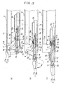
- Figure 2 is a side view showing the operation of the electronic apparatus 1 according to the embodiment
- Figure 3 is an exploded perspective view showing the electronic apparatus 1
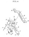
- Figure 4 is an exploded perspective view showing the substantial part related to Figure 3.
- the electronic apparatus used as one DIN-size car audio system, car navigation system or the like installed in a car dashboard (not shown), includes a housing 2, a first panel (outer panel) 3 disposed on the front face side of the housing 2, and a second panel (inner panel) 4 disposed behind the first panel.
- a slider 5 capable of sliding in forward and backward directions of the housing 2.
- a slot 5c On the bottom face of the slider 5, there are formed a slot 5c.
- the slot 5c engages with projections 2a protruding from the bottom face of the housing 2, thus allowing the slider 5 to smoothly slide in forward and backward directions of the housing 2.
- a rack 5b is fastened to the slider 5.
- the rack 5b gears with a pinion 13a fastened to the side face of the housing 2.
- pinion 13a is rotated with the operation of a motor 13m, the slider 5 slides in forward and backward directions of the housing 2.
- the first panel 3 and second panel 4 are linked to the slider 5 so that the panels 3 and 4 can rotate independently of each other around pins 3r and 4r each disposed in the lower end section of the panels (in Figures 3 and 4, there is illustrated a case where the lower end sections of holders 3h and 4h of the first panel 3 and second panel 4 are rotatably attached to the slider 5 with pins.)
- an operation section 3a and a display section 4a on one face of the first panel 3 and second panel 4, there are provided an operation section 3a and a display section 4a, respectively.
- operation section 3a and display section 4a there are disposed operation buttons and a screen display unit, respectively.
- a panel cover 3b capable of hiding the front face of the housing 2 when the first panel 3 and second panel 4 are received in the housing 2 side.
- the main body of apparatus 11 including reproducing units for recording media M, such as CD, CD-ROM, DVD, MD and cassette tape.
- a pulley 3p having the same axis as the pin 3r located at the lower end section of the first panel 3 is fastened to the holder 3h of the first panel 3.
- a panel rotating belt 10 is provided along the sliding direction of the slider 5 between the pulley 3p and a pulley 10a disposed behind the pulley 3p.
- a belt driving unit 12 for driving the panel rotating belt 10.
- a motor 12m of the belt driving unit 12 When a motor 12m of the belt driving unit 12 is operated, the pulley 10a is rotated via a gear 12a by the rotation of the motor 12m, whereby the first panel 3 is rotated around the pin 3r located at the lower end section of the first panel 3.
- the belt driving unit 12 is covered with a cover 12b. Thus, even when the belt driving unit 12 is moved in the housing 2 together with the slider 5, the gear of the belt driving unit is prevented from hitting against the wiring, etc. located inside the housing 2.
- a cam 6 with a cam slot 6a is attached to the inner side wall of the housing 2 along the forward and backward directions of the housing 2.
- the cam slot 6a is bored in a shape such that the tip end section of the cam slot bends downward in the front side of the housing 2.
- slider slot 5a On the side face of the slider 5, as shown in Figures 2 to 4, there is formed a slider slot 5a along the sliding direction of the slider 5.
- the slider slot 5a is bored in a shape such that the tip end section of slider slot bends upward in the front side of the housing 2.
- a pin 7a In the other end section of the arm 7, there is formed a pin 7a.
- a pin 8a of an arm bracket 8 is rotatably attached to the pin 7a.
- the arm bracket has another pin 8b formed therein. The pins 8a and 8b slide along the slider slot 5a together with the pin 7a of the arm 7.
- the first panel 3 is rotated by the operation of the panel rotating belt 10 so that the upper end section of the first panel 3 is moved forward out of the housing 2. Then, the first panel 3 stops at an angle substantially parallel with the sliding direction of the slider 5, whereby the operation panel 3a is exposed on the upper side of the first panel 3.
- the operation buttons installed in the operation panel 3a are operated to drive the panel rotating belt 10 so that the angle of the first panel 3 can be adjusted.
- the operation section 3a and display section 4a are inside opposed face-to-face with each other , thereby enabling the prevention of adhesion of dirt from the outside, theft, and so on.
- first panel 3 and second panel 4 are unfolded so that the operation buttons provided in the operation section 3a and the screen display unit provided in the display section 4a are exposed forward out of the housing 2. Consequently, compared with a structure in which a single panel, provided with operation buttons and a screen display unit, is half-turned to be received inside, there is obtained an electronic apparatus in which protection from theft is achieved and at the same time, a larger installing section for operation buttons, etc. and a larger screen display unit can be formed to achieve excellent operability.
- the angles of the first panel 3 and second panel 4 can be changed independently of each other. Accordingly, the operation buttons provided in the operation section 3a of the first panel can be adjusted to an angle such that the operation buttons can be easily pressed. At the same time, the screen display unit on the display section 4a of the second panel can be adjusted to an angle such that the screen display unit can be easily viewed.
- the recording-medium insertion slot 11a is provided on the front face of the main body of apparatus 11 disposed inside the housing 2 behind the first panel 3 and second panel 4.
- the first panel 3 and second panel 4 can be rotated forward out of the housing 2 to a substantially horizontal state relative to the slider 5.
- a space is formed between the housing 2 and the upper end section of the second panel 4. Through this space, a recording medium M can be removed and inserted from/to the recording-medium insertion slot 11a.
- the recording-medium insertion slot 11a is not required to be exposed on the front face of the housing 2 when the first panel 3 and second panel 4 are received in the housing 2 side.
- the panels can occupy the space for the recording-medium insertion slot, whereby a larger panel can be provided.
- the panel cover 3b of the first panel 3 is detachable from the first panel 3.
- the first panel 3 and second panel 4 are received in the housing 2 side.
- the internal structure of the first panel 3 can be exposed so that it looks as if some components of the electronic apparatus are missing, thereby achieving protection from theft.
- the invention is not limited thereto, but is also applicable to ordinary audio apparatuses, compact or mobile TV sets, car navigation apparatuses, and other various measurement apparatuses and home electric appliances.
- the operation section provided in the first panel and the display section provided in the second panel are inside opposed face-to-face with each other, thereby enabling the prevention of adhesion of dirt from the outside, theft, and so on.
- first panel and second panel are unfolded so that the operation section of the first panel and the display section of the second panel are exposed forward out of the housing. Consequently, compared with a structure in which a single panel with operation buttons and a screen display unit provided therein is half-turned to be received inside, there is obtained an electronic apparatus in which protection from theft is achieved and at the same time, a larger operation buttons or a larger screen display unit can be formed to achieve excellent operability.
Landscapes
- Engineering & Computer Science (AREA)
- Mechanical Engineering (AREA)
- Chemical & Material Sciences (AREA)
- Combustion & Propulsion (AREA)
- Transportation (AREA)
- Fittings On The Vehicle Exterior For Carrying Loads, And Devices For Holding Or Mounting Articles (AREA)
- Casings For Electric Apparatus (AREA)
- Devices For Indicating Variable Information By Combining Individual Elements (AREA)
Applications Claiming Priority (3)
| Application Number | Priority Date | Filing Date | Title |
|---|---|---|---|
| JP2002264453 | 2002-09-10 | ||
| JP2002264453 | 2002-09-10 | ||
| PCT/JP2003/009759 WO2004024509A1 (ja) | 2002-09-10 | 2003-07-31 | 電子機器 |
Publications (3)
| Publication Number | Publication Date |
|---|---|
| EP1550582A1 true EP1550582A1 (de) | 2005-07-06 |
| EP1550582A4 EP1550582A4 (de) | 2005-12-21 |
| EP1550582B1 EP1550582B1 (de) | 2007-02-14 |
Family
ID=31986522
Family Applications (1)
| Application Number | Title | Priority Date | Filing Date |
|---|---|---|---|
| EP03795207A Expired - Lifetime EP1550582B1 (de) | 2002-09-10 | 2003-07-31 | Elektronische vorrichtung |
Country Status (7)
| Country | Link |
|---|---|
| US (1) | US7568663B2 (de) |
| EP (1) | EP1550582B1 (de) |
| JP (1) | JP4184343B2 (de) |
| CN (1) | CN1319779C (de) |
| AU (1) | AU2003252303A1 (de) |
| DE (2) | DE60311849T2 (de) |
| WO (1) | WO2004024509A1 (de) |
Cited By (5)
| Publication number | Priority date | Publication date | Assignee | Title |
|---|---|---|---|---|
| FR2916289A1 (fr) * | 2007-05-15 | 2008-11-21 | Adm Concept Sa | Microordinateur pour planche de bord et planche de bord pourvue d'un tel ordinateur. |
| CN101434219B (zh) * | 2005-09-28 | 2010-09-08 | 富士通天株式会社 | 车载用电子装置 |
| EP1880903A4 (de) * | 2005-05-09 | 2011-01-26 | Fujitsu Ten Ltd | Elektronische vorrichtung |
| CN113543544A (zh) * | 2021-06-22 | 2021-10-22 | 王嘉豪 | 一种集成电路测试用脉冲信号产生器 |
| CN115230603A (zh) * | 2022-07-15 | 2022-10-25 | 东风汽车集团股份有限公司 | 一种中控屏固定座及安装方法 |
Families Citing this family (19)
| Publication number | Priority date | Publication date | Assignee | Title |
|---|---|---|---|---|
| US7665709B2 (en) | 2004-06-14 | 2010-02-23 | Sava Cvek | Trolley and rail systems for extension and retraction arrangements |
| WO2006063280A2 (en) * | 2004-12-08 | 2006-06-15 | Sava Cvek | Computer components adjustable between storage and use configurations |
| WO2006063279A2 (en) * | 2004-12-08 | 2006-06-15 | Sava Cvek | Emergency and security condition retractable computer arrangements |
| JP4150733B2 (ja) * | 2005-05-10 | 2008-09-17 | 株式会社ケンウッド | ディスク駆動装置 |
| JP4513015B2 (ja) * | 2005-06-09 | 2010-07-28 | ソニー株式会社 | 電子機器の筐体ボディ装着用フロントパネルアセンブリおよび車載用電子機器の筐体 |
| DE102006025383B3 (de) * | 2006-05-31 | 2007-12-13 | Siemens Ag | Bordmonitoreinrichtung |
| US7733659B2 (en) * | 2006-08-18 | 2010-06-08 | Delphi Technologies, Inc. | Lightweight audio system for automotive applications and method |
| US7894194B2 (en) * | 2008-01-25 | 2011-02-22 | Aten International Co., Ltd. | Rack-mounted foldable computer console for KVM switch |
| JP5115228B2 (ja) * | 2008-02-07 | 2013-01-09 | 株式会社Jvcケンウッド | パネル着脱機構およびそれを有する車載装置 |
| GB2475559B (en) * | 2009-11-24 | 2014-12-24 | Gm Global Tech Operations Inc | Multi functional device for a center stack |
| US10010169B2 (en) * | 2011-04-02 | 2018-07-03 | Eric Arthur Grotenhuis | Computer work desk |
| CN102592631B (zh) * | 2011-12-20 | 2014-12-24 | 苏州佳世达光电有限公司 | 对象驱动装置 |
| CN103909873B (zh) * | 2013-01-06 | 2016-05-18 | 李高伟 | 一种将平板电脑嵌入车辆仪表台的装置 |
| JP6218547B2 (ja) * | 2013-05-23 | 2017-10-25 | アルパイン株式会社 | 表示装置 |
| KR101481289B1 (ko) * | 2013-07-05 | 2015-01-09 | 현대자동차주식회사 | 차량용 에이브이엔 모니터 작동장치 |
| WO2018040213A1 (zh) * | 2016-08-31 | 2018-03-08 | 无锡小天鹅股份有限公司 | 衣物处理装置 |
| EP3626540B1 (de) * | 2018-09-19 | 2020-12-09 | Grammer Ag | Aufklappbarer einrichtungsgegenstand für lastkraftwagenkabine |
| CN110920527B (zh) * | 2018-09-19 | 2023-04-25 | 格拉默公司 | 货车驾驶室设备配件 |
| US20220097618A1 (en) * | 2020-09-30 | 2022-03-31 | Nissan North America, Inc. | Vehicular Electronics Module Installation and Removal |
Family Cites Families (24)
| Publication number | Priority date | Publication date | Assignee | Title |
|---|---|---|---|---|
| US4496943A (en) * | 1982-11-18 | 1985-01-29 | Portable Terminal Corp. | Portable information display |
| US4704604A (en) * | 1984-11-28 | 1987-11-03 | Zenith Electronics Corporation | Pivoting mount for detachable keyboard |
| US4874110A (en) * | 1988-10-27 | 1989-10-17 | Chrysler Motors Corporation | Lens structure for a combined radio/audio tape cassette player or the like |
| DE3930188C1 (de) * | 1989-09-09 | 1991-01-31 | Rittal-Werk Rudolf Loh Gmbh & Co Kg, 6348 Herborn, De | |
| JPH0687095A (ja) | 1992-09-08 | 1994-03-29 | Kawasaki Steel Corp | 溶接用タブ部材 |
| US5307327A (en) * | 1992-12-24 | 1994-04-26 | Chrysler Corporation | Mounting assembly for automotive audio components |
| US5388032A (en) * | 1993-05-04 | 1995-02-07 | Ibus Technologies, Inc. | Computer equipment monitor and discriminator |
| JP2581996Y2 (ja) * | 1993-05-31 | 1998-09-24 | アルパイン株式会社 | 表示装置 |
| JPH07246886A (ja) * | 1994-03-10 | 1995-09-26 | Alpine Electron Inc | 車載用機器の操作装置 |
| US5467947A (en) * | 1994-04-08 | 1995-11-21 | Metra Electronics Corporation | Mounting kit for mounting one of several types of audio equipment in an automotive dashboard |
| JP3227329B2 (ja) * | 1994-12-29 | 2001-11-12 | 株式会社ケンウッド | 車載用電子機器の盗難防止装置 |
| JPH09180332A (ja) * | 1995-12-28 | 1997-07-11 | Sony Corp | 電子機器 |
| JPH09286283A (ja) * | 1996-04-19 | 1997-11-04 | Aisin Aw Co Ltd | 車載用電子機器組立体 |
| JP3477551B2 (ja) * | 1999-06-29 | 2003-12-10 | 株式会社ケンウッド | 車載用音響機器の操作パネル反転機構 |
| US6353531B1 (en) * | 1999-08-25 | 2002-03-05 | Dell Usa, L.P. | Integrated visor for a notebook computer |
| JP2001202764A (ja) * | 2000-01-17 | 2001-07-27 | Kenwood Corp | 車載用電子機器及びパネル回動制御方法 |
| JP4251765B2 (ja) * | 2000-10-03 | 2009-04-08 | アルパイン株式会社 | 車載用電子機器 |
| JP2002166786A (ja) * | 2000-12-04 | 2002-06-11 | Alpine Electronics Inc | 車載用電子機器 |
| JP4662395B2 (ja) * | 2000-12-14 | 2011-03-30 | アルパイン株式会社 | 車載用電子機器 |
| JP4289786B2 (ja) * | 2000-12-18 | 2009-07-01 | アルパイン株式会社 | 車載用電子機器 |
| JP3740022B2 (ja) * | 2001-03-05 | 2006-01-25 | パイオニア株式会社 | 電子機器 |
| JP4328033B2 (ja) * | 2001-03-05 | 2009-09-09 | パイオニア株式会社 | 駆動機構 |
| JP2002347529A (ja) * | 2001-05-24 | 2002-12-04 | Pioneer Electronic Corp | 電子機器 |
| JP2003237484A (ja) * | 2002-02-13 | 2003-08-27 | Sony Corp | 車載用電子機器 |
-
2003
- 2003-07-31 WO PCT/JP2003/009759 patent/WO2004024509A1/ja not_active Ceased
- 2003-07-31 DE DE60311849T patent/DE60311849T2/de not_active Expired - Lifetime
- 2003-07-31 AU AU2003252303A patent/AU2003252303A1/en not_active Abandoned
- 2003-07-31 DE DE03795207T patent/DE03795207T1/de active Pending
- 2003-07-31 CN CNB038214741A patent/CN1319779C/zh not_active Expired - Fee Related
- 2003-07-31 US US10/527,131 patent/US7568663B2/en not_active Expired - Fee Related
- 2003-07-31 JP JP2004535865A patent/JP4184343B2/ja not_active Expired - Fee Related
- 2003-07-31 EP EP03795207A patent/EP1550582B1/de not_active Expired - Lifetime
Cited By (7)
| Publication number | Priority date | Publication date | Assignee | Title |
|---|---|---|---|---|
| EP1880903A4 (de) * | 2005-05-09 | 2011-01-26 | Fujitsu Ten Ltd | Elektronische vorrichtung |
| CN101434219B (zh) * | 2005-09-28 | 2010-09-08 | 富士通天株式会社 | 车载用电子装置 |
| FR2916289A1 (fr) * | 2007-05-15 | 2008-11-21 | Adm Concept Sa | Microordinateur pour planche de bord et planche de bord pourvue d'un tel ordinateur. |
| CN113543544A (zh) * | 2021-06-22 | 2021-10-22 | 王嘉豪 | 一种集成电路测试用脉冲信号产生器 |
| CN113543544B (zh) * | 2021-06-22 | 2023-11-03 | 合肥雷芯智能科技有限公司 | 一种集成电路测试用脉冲信号产生器 |
| CN115230603A (zh) * | 2022-07-15 | 2022-10-25 | 东风汽车集团股份有限公司 | 一种中控屏固定座及安装方法 |
| CN115230603B (zh) * | 2022-07-15 | 2025-05-27 | 东风汽车集团股份有限公司 | 一种中控屏固定座及安装方法 |
Also Published As
| Publication number | Publication date |
|---|---|
| CN1681687A (zh) | 2005-10-12 |
| US20050236527A1 (en) | 2005-10-27 |
| DE03795207T1 (de) | 2005-12-15 |
| US7568663B2 (en) | 2009-08-04 |
| JP4184343B2 (ja) | 2008-11-19 |
| CN1319779C (zh) | 2007-06-06 |
| DE60311849T2 (de) | 2008-03-06 |
| WO2004024509A1 (ja) | 2004-03-25 |
| AU2003252303A1 (en) | 2004-04-30 |
| EP1550582B1 (de) | 2007-02-14 |
| EP1550582A4 (de) | 2005-12-21 |
| JPWO2004024509A1 (ja) | 2006-01-05 |
| DE60311849D1 (de) | 2007-03-29 |
Similar Documents
| Publication | Publication Date | Title |
|---|---|---|
| EP1550582A1 (de) | Elektronische vorrichtung | |
| JP3227329B2 (ja) | 車載用電子機器の盗難防止装置 | |
| EP1440848A1 (de) | Fahrzeugmontierte elektronische vorrichtung | |
| JP4305840B2 (ja) | 車載用電子機器及びその機器に接続するパネル装着台 | |
| JP2005324678A (ja) | 2部材駆動装置および乗り物用遮蔽体 | |
| JPH10114247A (ja) | 車載用電子機器 | |
| US7119455B2 (en) | Automotive electronic device | |
| JP2017171085A (ja) | 車載装置 | |
| JP4370566B2 (ja) | 表示パネル | |
| JP4785424B2 (ja) | 電子機器 | |
| JP4662395B2 (ja) | 車載用電子機器 | |
| JP4007753B2 (ja) | 車載用電子機器 | |
| JP3562721B2 (ja) | 電子装置 | |
| JP2012224192A (ja) | 車載表示装置 | |
| JP4265808B2 (ja) | 車載用電子機器 | |
| JP2002166786A (ja) | 車載用電子機器 | |
| JP3931077B2 (ja) | 電子機器 | |
| JP3898911B2 (ja) | 車載用電子機器 | |
| JPH0640023Y2 (ja) | 車載用ディスプレイ装置 | |
| JP3647297B2 (ja) | 車載用電子機器 | |
| JP3701257B2 (ja) | 車載用電子機器 | |
| JP3597406B2 (ja) | 電子機器 | |
| JPH07246886A (ja) | 車載用機器の操作装置 | |
| JP4931513B2 (ja) | 車載用表示装置 | |
| JP3597407B2 (ja) | 電子機器 |
Legal Events
| Date | Code | Title | Description |
|---|---|---|---|
| PUAI | Public reference made under article 153(3) epc to a published international application that has entered the european phase |
Free format text: ORIGINAL CODE: 0009012 |
|
| 17P | Request for examination filed |
Effective date: 20050307 |
|
| AK | Designated contracting states |
Kind code of ref document: A1 Designated state(s): AT BE BG CH CY CZ DE DK EE ES FI FR GB GR HU IE IT LI LU MC NL PT RO SE SI SK TR |
|
| AX | Request for extension of the european patent |
Extension state: AL LT LV MK |
|
| EL | Fr: translation of claims filed | ||
| RIC1 | Information provided on ipc code assigned before grant |
Ipc: 7B 60K 35/00 A Ipc: 7G 11B 33/02 B Ipc: 7H 05K 5/03 B Ipc: 7B 60R 11/02 B Ipc: 7G 06F 3/02 B |
|
| DET | De: translation of patent claims | ||
| A4 | Supplementary search report drawn up and despatched |
Effective date: 20051104 |
|
| DAX | Request for extension of the european patent (deleted) | ||
| RBV | Designated contracting states (corrected) |
Designated state(s): DE FR GB IT |
|
| GRAP | Despatch of communication of intention to grant a patent |
Free format text: ORIGINAL CODE: EPIDOSNIGR1 |
|
| GRAS | Grant fee paid |
Free format text: ORIGINAL CODE: EPIDOSNIGR3 |
|
| GRAA | (expected) grant |
Free format text: ORIGINAL CODE: 0009210 |
|
| AK | Designated contracting states |
Kind code of ref document: B1 Designated state(s): DE FR GB IT |
|
| REG | Reference to a national code |
Ref country code: GB Ref legal event code: FG4D |
|
| REF | Corresponds to: |
Ref document number: 60311849 Country of ref document: DE Date of ref document: 20070329 Kind code of ref document: P |
|
| ET | Fr: translation filed | ||
| PLBE | No opposition filed within time limit |
Free format text: ORIGINAL CODE: 0009261 |
|
| STAA | Information on the status of an ep patent application or granted ep patent |
Free format text: STATUS: NO OPPOSITION FILED WITHIN TIME LIMIT |
|
| 26N | No opposition filed |
Effective date: 20071115 |
|
| REG | Reference to a national code |
Ref country code: DE Ref legal event code: R081 Ref document number: 60311849 Country of ref document: DE Owner name: JVC KENWOOD CORPORATION, YOKOHAMA-SHI, JP Free format text: FORMER OWNER: KABUSHIKI KAISHA KENWOOD, HACHIOJI, TOKYO, JP Effective date: 20120430 |
|
| REG | Reference to a national code |
Ref country code: FR Ref legal event code: TP Owner name: JVC KENWOOD CORPORATION, JP Effective date: 20120705 |
|
| PGFP | Annual fee paid to national office [announced via postgrant information from national office to epo] |
Ref country code: DE Payment date: 20130724 Year of fee payment: 11 |
|
| PGFP | Annual fee paid to national office [announced via postgrant information from national office to epo] |
Ref country code: FR Payment date: 20130724 Year of fee payment: 11 Ref country code: GB Payment date: 20130731 Year of fee payment: 11 |
|
| PGFP | Annual fee paid to national office [announced via postgrant information from national office to epo] |
Ref country code: IT Payment date: 20130717 Year of fee payment: 11 |
|
| REG | Reference to a national code |
Ref country code: DE Ref legal event code: R119 Ref document number: 60311849 Country of ref document: DE |
|
| GBPC | Gb: european patent ceased through non-payment of renewal fee |
Effective date: 20140731 |
|
| REG | Reference to a national code |
Ref country code: FR Ref legal event code: ST Effective date: 20150331 |
|
| PG25 | Lapsed in a contracting state [announced via postgrant information from national office to epo] |
Ref country code: IT Free format text: LAPSE BECAUSE OF NON-PAYMENT OF DUE FEES Effective date: 20140731 Ref country code: DE Free format text: LAPSE BECAUSE OF NON-PAYMENT OF DUE FEES Effective date: 20150203 |
|
| REG | Reference to a national code |
Ref country code: DE Ref legal event code: R119 Ref document number: 60311849 Country of ref document: DE Effective date: 20150203 |
|
| PG25 | Lapsed in a contracting state [announced via postgrant information from national office to epo] |
Ref country code: GB Free format text: LAPSE BECAUSE OF NON-PAYMENT OF DUE FEES Effective date: 20140731 Ref country code: FR Free format text: LAPSE BECAUSE OF NON-PAYMENT OF DUE FEES Effective date: 20140731 |