EP1550599B1 - Dispositif de colonne de direction a absorption d'energie de collision - Google Patents
Dispositif de colonne de direction a absorption d'energie de collision Download PDFInfo
- Publication number
- EP1550599B1 EP1550599B1 EP03799083A EP03799083A EP1550599B1 EP 1550599 B1 EP1550599 B1 EP 1550599B1 EP 03799083 A EP03799083 A EP 03799083A EP 03799083 A EP03799083 A EP 03799083A EP 1550599 B1 EP1550599 B1 EP 1550599B1
- Authority
- EP
- European Patent Office
- Prior art keywords
- energy
- absorbing
- steering column
- load
- secondary collision
- Prior art date
- Legal status (The legal status is an assumption and is not a legal conclusion. Google has not performed a legal analysis and makes no representation as to the accuracy of the status listed.)
- Expired - Lifetime
Links
- 238000010521 absorption reaction Methods 0.000 claims description 113
- 238000006073 displacement reaction Methods 0.000 claims description 55
- 230000008859 change Effects 0.000 claims description 10
- 230000007246 mechanism Effects 0.000 description 90
- 230000002787 reinforcement Effects 0.000 description 49
- XEEYBQQBJWHFJM-UHFFFAOYSA-N Iron Chemical compound [Fe] XEEYBQQBJWHFJM-UHFFFAOYSA-N 0.000 description 36
- 230000009471 action Effects 0.000 description 28
- 229910052742 iron Inorganic materials 0.000 description 18
- 230000007704 transition Effects 0.000 description 5
- 230000004044 response Effects 0.000 description 4
- 241001232202 Chrysothamnus stylosus Species 0.000 description 3
- 238000003780 insertion Methods 0.000 description 3
- 230000037431 insertion Effects 0.000 description 3
- 230000000694 effects Effects 0.000 description 2
- 229910000831 Steel Inorganic materials 0.000 description 1
- 239000006096 absorbing agent Substances 0.000 description 1
- 238000005452 bending Methods 0.000 description 1
- 239000002184 metal Substances 0.000 description 1
- 229910052751 metal Inorganic materials 0.000 description 1
- 230000004048 modification Effects 0.000 description 1
- 238000012986 modification Methods 0.000 description 1
- 210000003254 palate Anatomy 0.000 description 1
- 239000007787 solid Substances 0.000 description 1
- 239000010959 steel Substances 0.000 description 1
Images


















Classifications
-
- F—MECHANICAL ENGINEERING; LIGHTING; HEATING; WEAPONS; BLASTING
- F16—ENGINEERING ELEMENTS AND UNITS; GENERAL MEASURES FOR PRODUCING AND MAINTAINING EFFECTIVE FUNCTIONING OF MACHINES OR INSTALLATIONS; THERMAL INSULATION IN GENERAL
- F16F—SPRINGS; SHOCK-ABSORBERS; MEANS FOR DAMPING VIBRATION
- F16F7/00—Vibration-dampers; Shock-absorbers
- F16F7/12—Vibration-dampers; Shock-absorbers using plastic deformation of members
- F16F7/128—Vibration-dampers; Shock-absorbers using plastic deformation of members characterised by the members, e.g. a flat strap, yielding through stretching, pulling apart
-
- B—PERFORMING OPERATIONS; TRANSPORTING
- B62—LAND VEHICLES FOR TRAVELLING OTHERWISE THAN ON RAILS
- B62D—MOTOR VEHICLES; TRAILERS
- B62D1/00—Steering controls, i.e. means for initiating a change of direction of the vehicle
- B62D1/02—Steering controls, i.e. means for initiating a change of direction of the vehicle vehicle-mounted
- B62D1/16—Steering columns
- B62D1/18—Steering columns yieldable or adjustable, e.g. tiltable
- B62D1/184—Mechanisms for locking columns at selected positions
-
- B—PERFORMING OPERATIONS; TRANSPORTING
- B62—LAND VEHICLES FOR TRAVELLING OTHERWISE THAN ON RAILS
- B62D—MOTOR VEHICLES; TRAILERS
- B62D1/00—Steering controls, i.e. means for initiating a change of direction of the vehicle
- B62D1/02—Steering controls, i.e. means for initiating a change of direction of the vehicle vehicle-mounted
- B62D1/16—Steering columns
- B62D1/18—Steering columns yieldable or adjustable, e.g. tiltable
- B62D1/19—Steering columns yieldable or adjustable, e.g. tiltable incorporating energy-absorbing arrangements, e.g. by being yieldable or collapsible
- B62D1/195—Yieldable supports for the steering column
Definitions
- the present invention relates to an impact-absorbing steering column apparatus according to the preamble of claim 1 of the invention having collision-energy-absorbing means for absorbing secondary collision energy of an occupant (driver) in the event of a collision of a vehicle.
- EP 0 655 383 discloses such a steering column, including the features of the preamble of claim 1.
- a conventional impact-absorbing steering column apparatus effects absorption of secondary collision energy such that column drive means causes a steering column to retreat in relation to an occupant in accordance with the distance between the occupant and a steering wheel or the position of the steering column in relation to the occupant or such that energy absorption quantity adjustment means varies, in accordance with the distance or the position, the quantity of secondary impact energy to be absorbed by collision-energy-absorbing means.
- Such an impact-absorbing steering column apparatus is disclosed in, for example, Japanese Patent Application Laid-Open ( kokai ) No. 2002-79944 .
- the above-mentioned conventional impact-absorbing steering column apparatus is configured such that the column drive means and the energy absorption quantity adjustment means are operated under the control of an electrical control unit.
- the distance between the occupant and the steering wheel or the position of the steering column in relation to the occupant is electrically detected.
- the column drive means or the energy absorption quantity adjustment means is electrically controlled.
- US-B1-6 322 103 describes an actively variable energy absorber for a steering column, which counteracts a linear translation of a steering column housing in the direction of the centerline of the steering column due to a collision of a driver with a steering wheel. Thereby, the driver is decelerated by converting the kinetic energy of his motion into deformation energy of a flat metal strap being bent by means of a counterpart.
- the present invention has been accomplished in order to solve the above problem, and an object of the invention is to change an absorption load for secondary collision energy of an occupant in the event of a secondary collision of the occupant with a steering system, by means of a mechanical action effected by the secondary collision.
- This object is achieved by an impact-absorbing steering column apparatus with the features of claim 1 of the invention.
- An aspect of the present invention provides an impact-absorbing steering column apparatus comprising collision-energy-absorbing means for absorbing secondary collision energy of an occupant in the event of a collision of a vehicle.
- the collision-energy-absorbing means comprises energy-absorption-load-changing means for changing an absorption load for the secondary collision energy.
- the energy-absorption-load-changing means is adapted to change the absorption load in accordance with displacement of a steering column, the displacement changing dependently on a secondary collision of the occupant with a steering system.
- the occupant moves in a certain direction toward the front of the vehicle while having certain kinetic energy, depending on whether or not the occupant wears a seat belt, a collision speed, a seat position, and like factors; and a certain secondary collision load is input to the steering system along a certain direction of a secondary collision.
- the energy-absorption-load-changing means of the collision-energy-absorbing means can change the absorption load for secondary collision in accordance with displacement of the steering column, the displacement changing dependently on a secondary collision of the occupant with the steering system.
- the steering column in accordance with the direction of the secondary collision of the occupant with the steering system and/or the magnitude of the collision load, the steering column is displaced or allowed to be readily displaced in a direction different from a direction along which the steering column moves in relation to the vehicle body toward the front of the vehicle while absorbing energy.
- an absorption load to be generated by the energy-absorption-load-changing means can be changed in accordance with the displacement of the steering column.
- an impact-absorbing steering column apparatus comprising collision-energy-absorbing means for absorbing secondary collision energy of an occupant in the event of a collision of a vehicle.
- the collision-energy-absorbing means comprises energy-absorption-load-changing means for changing an absorption load for the secondary collision energy.
- the energy-absorption-load-changing means is adapted to change the absorption load in accordance with displacement of the steering column in a direction intersecting a direction of relative movement of the steering column for absorbing collision energy induced by a secondary collision of the occupant.
- the occupant moves in a certain direction toward the front of the vehicle while having certain kinetic energy, depending on whether or not the occupant wears a seat belt, a collision speed, a seat position, and like factors; and a certain secondary collision load is input to the steering system along a certain direction of a secondary collision.
- the energy-absorption-load-changing means adapted to absorb energy can change an absorption load.
- the steering column in accordance with the direction of the secondary collision of the occupant with the steering system and/or the magnitude of the collision load, the steering column is displaced or allowed to be readily displaced in a direction different from a direction along which the steering column moves in relation to the vehicle body toward the front of the vehicle while absorbing energy.
- the energy-absorption-load-changing means changes the absorption load in accordance with a mode of displacement of the steering column.
- an absorption load to be generated by the energy-absorption-load-changing means is changed in accordance with a mode of displacement of the steering column, so that the absorption load can be changed in accordance with the displaced position of the steering column.
- the energy-absorption-load-changing means comprises an energy-absorbing member, and engagement means capable of engaging with the energy-absorbing member, and an engagement relation between the energy-absorbing member and the engagement means varies in accordance with a mode of displacement of the steering column, thereby changing the absorption load.
- the engagement relation between the energy-absorbing member and the engagement means can be varied in accordance with a mode of displacement of the steering column, whereby the absorption load can be changed.
- the engagement means is squeezing means for squeezing the energy-absorbing member; the energy-absorbing member has an energy-absorbing portion, which is squeezed by the squeezing means to thereby absorb energy; and an engagement relation between the squeezing means and the energy-absorbing portion varies in accordance with a mode of displacement of the steering column, thereby changing the absorption load.
- the engagement relation between the squeezing means and the energy-absorbing portion is varied in accordance with a mode of displacement of the steering column, whereby the absorption load can be changed.
- the engagement means is squeezing means for squeezing the energy-absorbing member;
- the energy-absorbing member has a plurality of energy-absorbing portions that differ in energy absorption load in relation to the squeezing means; and an engagement between the squeezing means and one of the plurality of energy-absorbing portions is selected in accordance with a mode of displacement of the steering column, thereby changing the absorption load.
- an engagement between the squeezing means and one of the plurality of energy-absorbing portions is selected in accordance with a mode of displacement of the steering column, whereby the absorption load can be changed.
- the engagement means is squeezing means for squeezing the energy-absorbing member; the squeezing means has a plurality of squeezing portions that differ in the quantity of draw/squeeze in squeezing the energy-absorbing member; and an engagement between the energy-absorbing member and one of the plurality of squeezing portions is selected in accordance with a mode of displacement of the steering column, thereby changing the absorption load.
- an engagement between the squeezing means and one of the plurality of squeezing portions is selected in accordance with a mode of displacement of the steering column, whereby the absorption load can be changed.
- the energy-absorbing member is a linear member capable of engaging with the engagement means; the engagement means is engaged with or is not engaged with the linear member in accordance with a mode of displacement of the steering column, thereby changing the absorption load.
- the engagement means is engaged with or is not engaged with the linear member in accordance with a mode of displacement of the steering column, whereby the absorption load can be changed.
- the energy-absorbing member is a plurality of linear members capable of engaging with the engagement means; the number of the linear members to be engaged with the engagement means varies in accordance with a mode of displacement of the steering column, thereby changing the absorption load.
- the number of the linear members to be engaged with the engagement means varies in accordance with a mode of displacement of the steering column, whereby the absorption load can be changed.
- the steering column comprises the energy-absorbing member, a ball adapted to plastically deform the energy-absorbing member, and ball support means for adjusting the quantity of plastic deformation to be effected by the ball; and the ball support means is moved in accordance with a mode of displacement of the steering column in such a manner as to vary an engagement relation between the energy-absorbing member and the ball in accordance with the mode, thereby changing the absorption load.
- the ball support means is moved in such a manner as to vary the engagement relation between the energy-absorbing member and the ball in accordance with a mode of displacement of the steering column, whereby the absorption load can be changed.
- the energy-absorbing member has an elongated groove having a predetermined width;
- the engagement means is squeezing means assuming a special shape and capable of being displaced in the elongated groove in relation to the energy-absorbing member; and an engagement relation between the special-shape squeezing means and the elongated groove of the energy-absorbing member varies in accordance with a mode of displacement of the steering column, thereby changing the absorption load.
- the engagement relation between the special-shape squeezing means and the elongated groove of the energy-absorbing member varies in accordance with a mode of displacement of the steering column, whereby the absorption load can be changed.
- an energy-absorbing member is provided on either a vehicle-body-side member or the steering column, the energy-absorbing member generating an energy absorption load by means of displacement in relation to either the vehicle-body-side member or the steering column on which the energy-absorbing member is provided; the engagement means capable of engaging with the energy-absorbing member is provided on either the vehicle-body-side member or the steering column on which the energy-absorbing member is not provided; and when the energy-absorbing member is engaged with the engagement means in accordance with a mode of displacement of the steering column, the mode changing dependently on a secondary collision, the energy-absorbing member incrementally changes the absorption load by means of displacement in relation to either the vehicle-body-side member or the steering column on which the energy-absorbing member is provided.
- the energy-absorbing member when the energy-absorbing member is engaged with the engagement means in accordance with a mode of displacement of the steering column, the mode of displacement changing dependently on a secondary collision, the energy-absorbing member can incrementally change the absorption load by means of displacement in relation to either the vehicle-body-side member or the steering column on which the energy-absorbing member is provided.
- the energy-absorption-load-changing means changes the absorption load in accordance with displacement of the steering column, the displacement changing dependently on the direction of a secondary collision of the occupant with the steering system.
- the energy-absorption-load-changing means can change the absorption load in accordance with displacement of the steering column, the displacement changing dependently on the direction of a secondary collision of the occupant with the steering system.
- the energy-absorption-load-changing means changes the absorption load in accordance with displacement of the steering column, the displacement changing dependently on the direction of a secondary collision of the occupant with the steering system at an initial stage of the secondary collision.
- the energy-absorption-load-changing means can change the absorption load in accordance with displacement of the steering column, the displacement changing dependently on the direction of a secondary collision of the occupant with the steering system at an initial stage of the secondary collision.
- the energy-absorption-load-changing means when a collision load associated with a secondary collision of the occupant with the steering system is equal to or greater than a predetermined value, the energy-absorption-load-changing means increases the absorption load.
- the energy-absorption-load-changing means can increase the absorption load.
- the energy-absorption-load-changing means increases the absorption load in accordance with such displacement that the steering column tilts upward as a result of a secondary collision of the occupant with the steering system.
- the energy-absorption-load-changing means can increase the absorption load in accordance with such displacement that the steering column tilts upward as a result of a secondary collision of the occupant with the steering system.
- the energy-absorption-load-changing means changes the absorption load in accordance with a direction of displacement of the steering column, the direction of displacement changing dependently on the direction of a secondary collision of the occupant with the steering system.
- the energy-absorption-load-changing means can increase the absorption load in accordance with the displaced position of the steering column, the displaced position changing dependently on the direction of a secondary collision of the occupant with the steering system.
- impact-absorbing means for absorbing a predetermined collision load is provided separately from the collision-energy-absorbing means.
- the impact-absorbing means for absorbing a predetermined collision load can be provided separately from the collision-energy-absorbing means.
- the collision-energy-absorbing means selectively provides the absorption load, or changes the magnitude of the absorption load.
- the collision-energy-absorbing means can determine whether to effect the absorption load or can change the magnitude of the absorption load.
- the loads changing dependently on a secondary collision of the occupant with the steering system
- deformation of an energy-absorbing member provided on either the steering column or the vehicle-body-side member is passively changed by engagement means provided on either the steering column or the vehicle-body-side member on which the energy-absorbing member is not provided, whereby the energy-absorption-load-changing means changes the absorption load.
- the loads changing dependently on a secondary collision of the occupant with the steering system
- deformation of the energy-absorbing member provided on either the steering column or the vehicle-body-side member is passively changed by the engagement means provided on either the steering column or the vehicle-body-side member on which the energy-absorbing member is not provided, whereby the absorption load can be changed.
- the engagement means is formed on the vehicle-body-side member; the energy-absorbing member is provided on the steering column in opposition to the engagement means and assumes an elongated shape extending along an axis of the steering column; and the engagement means provided on the vehicle-body-side member causes the deformation of the energy-absorbing member provided on the steering column.
- the engagement means is formed on the vehicle-body-side member; the energy-absorbing member is provided on the steering column in opposition to the engagement means and assumes an elongated shape extending along the axis of the steering column; and the engagement means provided on the vehicle-body-side member can cause the deformation of the energy-absorbing member provided on the steering column.
- abutment between the engagement means and the energy-absorbing member is enabled.
- the engagement means can abut the energy-absorbing member.
- the steering column in the event of a secondary collision, is allowed to be displaced in such a manner as to tilt toward the vehicle-body-side member.
- the steering column can be displaced in such a manner as to tilt toward the vehicle-body-side member.
- the absorption load is increased with a load of pressing the steering column against the vehicle-body-side member.
- the absorption load can be increased with the load of pressing the steering column against the vehicle-body-side member.
- impact-absorbing means for absorbing a predetermined collision load is provided separately from the collision-energy-absorbing means.
- the impact-absorbing means for absorbing a predetermined collision load can be provided separately from the collision-energy-absorbing means.
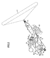
- FIGS. 1 to 8 show a first embodiment of an impact-absorbing steering column apparatus according to the present invention.
- a steering column 12 supports a steering shaft 11 rotatably and in an axially unmovable condition and is supported by a steering mounting member 20, which is a portion of a vehicle body, at a predetermined tilt angle by means of an upper support mechanism A and a lower support mechanism B.
- the lower end (front end) of the steering shaft 11 is linked to an intermediate shaft 14, which can extend and contract and can transmit torque, via a universal joint 13.
- a steering wheel 17, into which an airbag device is incorporated, is attached to the upper end (rear end) of the steering shaft 11 in a unitarily rotatable condition.
- the upper support mechanism A is adapted to support an upper region of the steering column 12.
- the upper support mechanism A supports the upper region of the steering column 12 such that the steering column 12 can be vertically moved for adjustment (the tilt of the steering column 12 can be adjusted).
- the upper support mechanism A supports the upper region of the steering column 12 such that the steering column 12 can tilt upward and can move frontward along its axis.
- the upper support mechanism A includes a support bracket 31 made of an iron plate, a column-side bracket 32 made of an iron plate, clamp means 40, and an operation lever 50 used to operate the clamp means 40.
- the support bracket 31 has laterally paired arms 31a and 31b extending downward and is fixedly attached to the steering mounting member 20 by use of laterally paired mounting bolts 39.
- the column-side bracket 32 has laterally paired arms 32a and 32b extending upward and is welded to the steering column 12.
- the clamp means 40 is adapted to frictionally engage the arms 32a and 32b of the column-side bracket 32 with the arms 31 a and 31 b of the support bracket 31 in a fixed condition or to disengage them.
- the steering mounting member 20 has a mounting portion 21 in its upper region for attachment of the upper support mechanism A and a mounting portion 22 in its lower region for attachment of the lower support mechanism B.
- the mounting portion 21 for the upper support mechanism A has a substantially U-shaped cross section, and a substantially V-shaped convex surface S1 located at its lower end.
- Laterally paired bolt insertion holes 21 b and 21 c are formed in the mounting portion 21 and allow the corresponding mounting bolts 39 to extend therethrough.
- Laterally paired nuts 23 and 24 into which the corresponding mounting bolts 39 are screwed are welded to the mounting portion 21 in alignment with the bolt insertion holes 21 b and 21 c, respectively.
- the support bracket 31 is composed of a plate 31A and a reinforcement plate 31B.
- the plate 31A has a substantially M-shaped cross section, and a substantially V-shaped concave surface S2 located at its top and coming into close contact with the substantially V-shaped convex surface S1 of the steering mounting member 20.
- the reinforcement plate 31 B is welded to laterally opposite lower end portions of the plate 31A so as to reinforce the plate 31A.
- the plate 31A includes the laterally paired arms 31 a and 31 b extending downward. Laterally paired bolt insertion holes 31 c (see FIG. 6 ) are formed in the plate 31A and allow the corresponding mounting bolts 39 to extend therethrough.
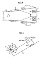
- laterally paired guide slots 31a1 and 31b1 extending frontward and laterally paired guide slots 31a2 and 31b2 extending frontward are formed in the arms 31a and 31b.
- the lower guide slots 31a1 and 31b1 are formed linearly, substantially in parallel with the axial direction of the steering column 12.
- the lower guide slots 31a1 and 31b1 and the corresponding upper guide slots 31a2 and 31b2 communicate with each other via corresponding transition portions 31a3 and 31b3 located at rear end portions of the guide slots.
- the upper guide slots 31a2 and 31b2 are formed linearly and extend upward at a predetermined angle ⁇ with respect to the corresponding lower guide slots 31 a1 and 31b1.
- the column-side bracket 32 includes the laterally paired arms 32a and 32b, which extend upward and are slidably engaged with the corresponding arms 31 a and 31 b of the support bracket 31 from the outside.
- Arcuately elongated holes 32a1 and 32b1 are formed in the corresponding arms 32a and 32b arcuately about support center O1 of the lower support mechanism B.
- the clamp means 40 includes a nonrotatable lock bolt 41, a collar 42, a nut 43, and a pair of laterally adjacent cam plates 44.
- the lock bolt 41 extends through the arcuately elongated holes 32a1 and 32b1 formed in the laterally opposite arms 32a and 32b of the column-side bracket 32 and through the guide slots 31a1 and 31 b1 or the guide slots 31a2 and 31b2 formed respectively in the laterally opposite arms 31 a and 31 b of the support bracket 31.
- the collar 42 is fitted onto the lock bolt 41 while extending between the laterally opposite arms 32a and 32b of the column-side bracket 32 and is fitted, at its laterally opposite end portions, into the guide slots 31a1 and 31b1 or the guide slots 31 a2 and 32b2.
- the nut 43 is screwed on an externally threaded portion 41 a of the lock bolt 41 and rotated by means of the operation lever 50.
- the paired cam plates 44 are mounted on the lock bolt 41 between the operation lever 50 and the left arm 32a of the column-side bracket 32.
- the detailed configuration of the paired, laterally adjacent cam plates 44 is the same as hat described in Japanese Patent Application Laid-Open ( kokai ) No. 2000-62624 ; therefore, repeated description thereof is omitted.
- the clamp means 40 functions as follows.
- the operation lever 50 is rotated counterclockwise in FIG. 1
- the nut 43 is fastened to the lock bolt 41
- the paired cam plates 44 convert rotation of the operation lever 50 to an axial stroke of the lock bolt 41.
- a predetermined frictional engagement is established between the arms 31 a and 32a of the brackets 31 and 32 and between the arms 31 b and 32b of the brackets 31 and 32, whereby the column-side bracket 32 is fixed (locked) to the support bracket 31.
- the operation lever 50 is rotated clockwise in FIG. 1
- the nut 43 is loosened, and thus the above frictional engagement is canceled.
- the column-side bracket 32 becomes tiltable in relation to the support bracket 31.
- a support plate 35 is attached to the support bracket 31, and vertically paired energy-absorbing members 36 and 37 are also attached to the support bracket 31.
- the support plate 35 extends laterally within the support bracket 31 and is welded, at its laterally opposite ends, to the arms 31 a and 31 b of the support bracket 31.
- the lower energy-absorbing member 36 is provided for use with the lower guide slots 31a1 and 31b1, and is a thin elongated plate having a predetermined width (a plate whose absorption load is small when absorbing secondary collision energy).
- a predetermined width a plate whose absorption load is small when absorbing secondary collision energy.
- the upper energy-absorbing member 37 is provided for use with the upper guide slots 31a2 and 31b2, and is a thick elongated plate having a predetermined width (a plate whose absorption load is large when absorbing secondary collision energy).
- a predetermined width a plate whose absorption load is large when absorbing secondary collision energy.
- the lower support mechanism B is adapted to support a lower region of the steering column 12.
- the lower support mechanism B supports the lower region of the steering column 12 in a tiltable (pivotable) condition.
- the lower support mechanism B supports the steering column 12 such that the steering column 12 can move frontward along its axis.
- the lower support mechanism B is composed of a vehicle-body-side bracket 61 made of an iron plate, a column-side bracket 62 made of an iron plate, and connection means 70.
- the vehicle-body-side bracket 61 includes laterally paired arms 61 a extending downward and is fixed to the steering mounting member 20.
- the column-side bracket 62 has a cross section resembling a squarish letter U and is welded to the steering column 12 at an upper portion of the column's outer circumferential surface in the column's lower region.
- the connection means 70 connects the column-side bracket 62 to the vehicle-body-side bracket 61 such that the column-side bracket 62 is movable along the column axis and tiltable.
- the connection means 70 is composed of laterally paired resin bushes 71 and 72, a collar 73, a bolt 74, and a nut (welded to the right-hand arm of the vehicle-body-side bracket 61), into which the bolt 74 is screwed in a fixed condition.
- the bushes 71 and 72 are fitted to corresponding laterally paired elongated holes 62a formed in the column-side bracket 62 and extending along the column axis and break under a predetermined load.
- the collar 73 is fitted into the resin bushes 71 and 72 and engaged, at its opposite ends, with the arms 61 a of the vehicle-body-side bracket 61.
- the bolt 74 extends through the collar 73 and through round mounting holes formed in the corresponding arms 61 a of the vehicle-body-side bracket 61 and unites the resin bushes 71 and 72 and the collar 73 with the vehicle-body-side bracket 61.
- a seat belt device 90 is attached to a seat 80 for an occupant H.
- the seat belt device 90 includes a seat belt 91, a tongue plate 92, a buckle 93, and a shoulder belt anchor 94, as well as a retractor 95 into which a pretensioner mechanism and a force limiter mechanism are incorporated.
- the seat belt 91 can restrain the occupant H.
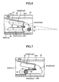
- the first embodiment functions as follows. Since the occupant H is restrained by the seat belt 91, the occupant H moves frontward while bending himself/herself forward. At the initial stage of a secondary collision of this case, a collision load from the occupant H is exerted on the steering column 12 in the direction of F1 (along the axis of the steering column 12) in FIG. 2 via the steering wheel 17 and the steering shaft 11. As a result of the collision load overcome the above-mentioned frictional engagement and a rupture load of the bushes 71 and 72, the steering column 12 moves frontward along its axial direction.
- the lock bolt 41 and the collar 42 in the upper support mechanism A move frontward along the guide slots 31a1 and 31b1, thereby plastically deforming the lower energy-absorbing member 36.
- the plastic deformation yields a small absorption load for secondary collision energy.
- the seat belt device 90 functions; and an air bag device incorporated in the steering wheel 17, and the energy-absorbing member 36, which is provided for use with the lower guide slots 31a1 and 31b1 in the upper support mechanism A, function sequentially, thereby absorbing secondary collision energy of the occupant H.
- the lock bolt 41 and the collar 42 move from rear end portions of the lower guide slots 31 a1 and 31b1 to rear end portions of the upper guide slots 31a2 and 31b2 via the transition portions 31a3 and 31b3. Subsequently, as shown in FIG. 8 , the lock bolt 41 and the collar 42 move frontward along the upper guide slots 31a2 and 31b2, thereby plastically deforming the upper energy-absorbing member 37. The plastic deformation yields a large absorption load for secondary collision energy.
- the air bag device incorporated in the steering wheel 17, and the energy-absorbing member 37 which is provided for use with the upper guide slots 31a2 and 31b2 in the upper support mechanism A, function sequentially, thereby absorbing secondary collision energy of the occupant H.
- the steering column 12 in the event of a collision of the vehicle, in accordance with, for example, whether or not the occupant H wears the seat belt 91, the occupant H moves frontward in a certain direction while having certain kinetic energy; and a certain secondary collision load (for example, F1 or F2) is input to the steering column 12 along a certain direction of a secondary collision.
- a certain secondary collision load for example, F1 or F2
- the steering column 12 is displaced in the direction of the secondary collision while being guided by the guide slots provided in the support bracket 31; specifically, by the guide slots 31a1 and 31b1, the guide slots 31a2 and 31b2, and the transition portions 31a3 and 31b3.
- the displacement causes the energy-absorbing member 36 provided for use with the guide slots 31a1 and 31b1 or the energy-absorbing member 37 provided for use with the guide slots 31a2 and 31b2 to function, whereby in the event of a secondary collision an absorption load for secondary collision energy is changed.
- energy-absorption-load-changing means including the guide slots 31a1 and 31 b1, the guide slots 31a2 and 31b2, and the transition portions 31a3 and 31b3 provided in the support bracket 31 changes the absorption load by means of a mechanical action effected in accordance with the direction of a secondary collision of the occupant H with the steering system.
- the first embodiment can be mechanically implemented by means of appropriately setting, for example, the shape of the guide slots 31a1 and 31b1, the shape of the guide slots 31a2 and 31b2, the shape of the transition portions 31a3 and 31b3, and the shape of the energy-absorbing members 36 and 37, without need to employ electrical control, whose cost is high, and thus at low cost.
- the lower energy-absorbing member 36 is formed of a thin, elongated plate having a predetermined width
- the upper energy-absorbing member 37 is formed of a thick, elongated plate having a predetermined width
- the energy-absorbing members 36 and 37 may be embodied as follows: the lower energy-absorbing member 36 is formed of a narrow, elongated plate having a predetermined thickness, and the upper energy-absorbing member 37 is formed of a wide, elongated plate having the predetermined thickness.
- the present invention is embodied in relation to a steering column assembly having a tilt function.
- the present invention may be similarly embodied in relation to a steering column assembly having no tilt function.
- two pairs of guide slots 31a1 and 31b1, and 31a2 and 31b2 are provided in the support bracket 31, and the energy-absorbing members 36 and 37 are provided for use with the corresponding guide slots.
- the number of guide slots and the number of energy-absorbing members may be increased as appropriate.
- two pairs of guide slots 31a1 and 31b1, and 31a2 and 31b2, and two kinds of corresponding energy-absorbing members 36 and 37 are provided in the support bracket 31, which is a vehicle-body-side member in the upper support mechanism A.
- the following configuration may be employed: two guide means are provided in the column-side bracket 32, which is a column-side member in the upper support mechanism A, and two kinds of energy-absorbing members are provided which correspond to these guide means.
- a support shaft (a member corresponding to the lock bolt 41) is fixedly attached to a vehicle-body-side support bracket.
- collision-energy-absorbing means which includes two pairs of guide slots 31a1 and 31b1, and 31a2 and 31b2, and two kinds of energy-absorbing members 36 and 37
- the collision-energy-absorbing means which includes two pairs of guide slots 31a1 and 31b1, and 31a2 and 31b2, and two kinds of energy-absorbing members 36 and 37
- the lower support mechanism B is provided in the lower support mechanism B.
- the rear end of the energy-absorbing member 36 is welded to the upper surface of the steering column 12
- the rear end of the energy-absorbing member 37 is welded to the lower surface of the upper wall of the column-side bracket 62.
- the energy-absorbing members 36 and 37 which are plastically deformed by means of the lock bolt 41 and the collar 42 to thereby absorb secondary collision energy, are formed of corresponding elongated plates provided separately from the support bracket 31.
- the following configuration may be employed: the guide slots 31a1 and 31b1 and the guide slots 31a2 and 31b2 formed in the support bracket 31 assume different widths such that the guide slot portions are plastically deformed by means of the lock bolt 41 and the collar 42 to thereby absorb secondary collision energy.
- the present invention is embodied in relation to a steering column assembly configured such that an upper region of the steering column 12 is supported by the upper support mechanism A in a frontward movable condition, and a lower region of the steering column 12 is supported by the lower support mechanism B in a frontward movable condition.
- the present invention may be similarly embodied in relation to a steering column assembly configured such that a steering column is supported by a single support mechanism in a frontward movable condition.
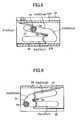
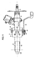
- FIGS. 10 to 14 show a second embodiment of the impact-absorbing steering column apparatus according to the present invention.
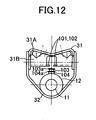
- collision-energy-absorbing means for absorbing secondary collision energy of the occupant H includes laterally paired energy-absorbing members 101 and 102 provided in the upper support mechanism A, engagement pins 103 and 104 provided on the steering column 12, and an energy-absorbing member 105 provided in the lower support mechanism B.
- Structural features other than the collision-energy-absorbing means for absorbing secondary collision energy of the occupant H are substantially identical with those of the above-described first embodiment and are thus denoted by common reference numerals, and repeated description thereof is omitted.
- the laterally paired energy-absorbing members 101 and 102 are elongated plates. When the engagement pin 103 or 104 is engaged with the energy-absorbing members 101 and 102 and passes frontward therebetween, the energy-absorbing members 101 and 102 are plastically deformed to thereby absorb secondary collision energy.
- the energy-absorbing members 101. and 102 are formed integrally with the reinforcement plate 31 B of the support bracket 31 in the upper support mechanism A.
- the energy-absorbing members 101 and 102 face each other with a predetermined gap formed therebetween and extend along the axial direction of the steering column 12.
- the engagement pins 103 and 104 are provided on the steering column 12 in such a manner as to project upward. Stoppers 103a and 104a are integrally formed at distal end portions of the engagement pins 103 and 104, respectively. The main purpose of the stoppers 103a and 104a is to prevent the engagement pin 103 or 104 from coming out of the gap between the energy-absorbing members 101 and 102 when the engagement pin 103 or 104 is fitted into the gap and moves frontward through the gap.
- the distal engagement pin 103 has a diameter slightly greater than the gap between the energy-absorbing members 101 and 102.
- the engagement pin 103 can be fitted into the gap between the energy-absorbing members 101 and 102.
- the engagement pin 103 fitted into the gap between the energy-absorbing members 101 and 102 can plastically deform the energy-absorbing members 101 and 102.
- the proximal engagement pin 104 has a diameter slightly greater than that of the distal engagement pin 103.
- the engagement pin 104 can be fitted into the gap between the energy-absorbing members 101 and 102.
- the engagement pin 104 fitted into the gap between the energy-absorbing members 101 and 102 can plastically deform the energy-absorbing members 101 and 102.
- the energy-absorbing member 105 provided in the lower support mechanism B is an elongated plate.
- the energy-absorbing member 105 is engaged with the collar 73 of the connection means 70 and plastically deformed to thereby absorb secondary collision energy.
- the energy-absorbing member 105 is fixedly attached, at its one end portion 105a, to the column-side bracket 62 in the lower support mechanism B; loops around the collar 73; and extends frontward.
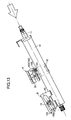
- the steering column 12 moves frontward along its axial direction.
- the engagement pins 103 and 104 is fitted into the gap between the energy-absorbing members 101 and 102, the energy-absorbing member 105 is plastically deformed by means of the collar 73.
- an absorption load for secondary collision energy is small.
- the distal engagement pin 103 is fitted into the gap between the energy-absorbing members 101 and 102 to thereby plastically deform the energy-absorbing members 101 and 102, while the energy-absorbing member 105 is plastically deformed by means of the collar 73.
- an absorption load for secondary collision energy is larger than that in the case of FIG. 13 .
- the proximal engagement pin 104 is fitted into the gap between the energy-absorbing members 101 and 102 to thereby plastically deform the energy-absorbing members 101 and 102, while the energy-absorbing member 105 is plastically deformed by means of the collar 73.
- energy-absorption-load-changing means including the engagement pins 103 and 104 changes an absorption load for secondary collision energy in accordance with the direction and load of a secondary collision of the occupant H with the steering system.
- the second embodiment can be mechanically implemented by means of appropriately setting, for example, the shape and arrangement of the engagement pins 103 and 104, without need to employ electrical control, whose cost is high, and thus at low cost.
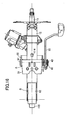
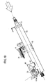
- FIGS. 15 to 19 show a third embodiment of the impact-absorbing steering column apparatus according to the present invention.
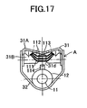
- collision-energy-absorbing means for absorbing secondary collision energy of the occupant H includes three energy-absorbing members 111, 112, and 113 provided in the upper support mechanism A; an engagement hook 114 provided on the steering column 12; and an energy-absorbing member 115 provided on the lower support mechanism B.
- Structural features other than the collision-energy-absorbing means for absorbing secondary collision energy of the occupant H are substantially identical with those of the above-described first embodiment and are thus denoted by common reference numerals, and repeated description thereof is omitted.
- the energy-absorbing members 111, 112, and 113 are iron bars and plastically deformed when the engagement hook 114 is engaged with them and moves frontward, thereby absorbing secondary collision energy.
- the energy-absorbing members 111, 112, and 113 are attached in array to the reinforcement plate 31 B of the support bracket 31 in the upper support mechanism A.
- Each of the energy-absorbing members 111, 112, and 113 is formed into a shape resembling the lying letter U that opens frontward and includes portions extending between its intermediate region and its front ends along the axial direction of the steering column 12. As shown in FIG. 17 , a rear end portion of each of the energy-absorbing members 111, 112, and 113 is curved downward and thus can be engaged with the engagement hook 114 substantially at its center.
- a cutout 31 d is formed in the reinforcement plate 31 B of the support bracket 31 in order to allow frontward movement of the engagement hook 114 engaged with the energy-absorbing member(s) 111 (112 and 113).
- the engagement hook 114 is provided on the steering column 12 in an upward projecting condition.
- the engagement hook 114 can engage with the energy-absorbing member(s) 111 (112 and 113). Being engaged with the energy-absorbing member(s) 111 (112 and 113), the engagement hook 114 can plastically deform the energy-absorbing member(s) 111 (112 and 113).
- the energy-absorbing member 115 provided in the lower support mechanism B is an elongated plate.
- the energy-absorbing member 115 is engaged with the collar 73 of the connection means 70 and plastically deformed to thereby absorb secondary collision energy.
- the energy-absorbing member 115 is fixedly attached, at its one end portion 105a, to the column-side bracket 62 in the lower support mechanism B; loops around the collar 73; and extends frontward.
- the steering column 12 moves frontward along its axial direction.
- the engagement hook 114 is engaged with none of the energy-absorbing members 111, 112, and 113, the energy-absorbing member 115 is plastically deformed by means of the collar 73.
- an absorption load for secondary collision energy is small.
- the engagement hook 114 is engaged with the bottom energy-absorbing member 111 to thereby plastically deform the energy-absorbing member 111, while the energy-absorbing member 115 is plastically deformed by means of the collar 73.
- an absorption load for secondary collision energy is larger than that in the case of FIG. 18 .
- energy-absorption-load-changing means including the energy-absorbing members 111, 112, and 113 and the engagement hook 114 changes an absorption load for secondary collision energy in accordance with the direction and load of a secondary collision of the occupant H with the steering system.
- the third embodiment can be mechanically implemented by means of appropriately setting, for example, the shape of the energy-absorbing members 111, 112, and 113 and the shape and arrangement of the engagement hook 114, without need to employ electrical control, whose cost is high, and thus at low cost.
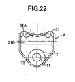
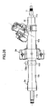
- FIGS. 20 to 24 show a fourth embodiment of the impact-absorbing steering column apparatus according to the present invention.
- collision-energy-absorbing means for absorbing secondary collision energy of the occupant H includes laterally paired energy-absorbing members 121 and 122, a cam 123, and an energy-absorbing member 124 provided on the lower support mechanism B.
- Structural features other than the collision-energy-absorbing means for absorbing secondary collision energy of the occupant H are substantially identical with those of the above-described first embodiment and are thus denoted by common reference numerals, and repeated description thereof is omitted.
- the laterally paired energy-absorbing members 121 and 122 are iron plates and plastically deformed when moving frontward while being engaged with the cam 123, thereby absorbing secondary collision energy.
- the laterally paired energy-absorbing members 121 and 122 are integrally formed with corresponding laterally paired vertical walls of the column-side bracket 62 in the lower support mechanism B and extend in the front-rear direction while being slightly inclined upward in relation to the axial direction of the steering column 12.
- the cam 123 is employed in place of the bushes 71, 72 and the collar 73 of the connection means 70.
- the cam 123 is nonrotatably attached to a square portion 74a of the bolt 74 at such an angle that one of four flat portions 123a formed on its outer surface in a diagonally facing condition is substantially aligned with the longitudinal direction of the laterally paired elongated holes 62a provided in the column-side bracket 62.
- the cam 123 is rotatable in relation to the elongated holes 62a.
- the cam 123 can be engaged with the energy-absorbing members 121, 122, and 124. Being engaged with the energy-absorbing members 121 and 122 and the energy-absorbing member 124, the cam 123 can plastically deform the energy-absorbing members 121, 122, and 124.
- the energy-absorbing member 124 is an elongated plate.
- the energy-absorbing member 124 is engaged with the cam 123 and plastically deformed to thereby absorb secondary collision energy.
- the energy-absorbing member 124 is fixedly attached, at its one end portion (not shown), to the column-side bracket 62; loops around the cam 123; and extends frontward (see FIG. 20 ).
- the steering column 12 moves frontward along its axial direction.
- the flat portions 123a of the cam 123 are engaged with the energy-absorbing members 121 and 122 (the energy-absorbing members 121 and 122 are hardly plastically deformed by means of the cam 123)
- the energy-absorbing member 124 is plastically deformed by means of the cam 123.
- corner portions of the cam 123 are engaged with the energy-absorbing members 121 and 122 to thereby plastically deform the energy-absorbing members 121 and 122, while the energy-absorbing member 124 is plastically deformed by means of the cam 123.
- an absorption load for secondary collision energy is larger than that in the case of FIG. 23 .
- energy-absorption-load-changing means including the energy-absorbing members 121, 122, and 124 and the cam 123 changes an absorption load for secondary collision energy in accordance with the direction and load of a secondary collision of the occupant H with the steering system.
- the fourth embodiment can be mechanically implemented by means of appropriately setting, for example, the shape and arrangement of the energy-absorbing members 121, 122, and 124 and the cam 123, without need to employ electrical control, whose cost is high, and thus at low cost.
- FIGS. 25 to 31 show a fifth embodiment of the impact-absorbing steering column apparatus according to the present invention.
- the fifth embodiment employs a ball-type collision-energy-absorbing device as collision-energy-absorbing means for absorbing secondary collision energy of the occupant H.
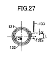
- the ball-type collision-energy-absorbing device includes a plurality of balls 131, a ring 132 for holding the balls 131, and a rod 133 capable of press-rotating the ring 132.
- the steering shaft 11 is composed of an upper shaft 11a and a lower shaft 11b.
- the upper shaft 11a and the lower shaft 11 b can axially extend and contract in relation to each other and can transmit torque.
- the steering column 12 is composed of an upper column 12a and a lower column 12b.
- the upper column 12a and the lower column 12b can axially extend and contract in relation to each other and support respectively the upper shaft 11 a and the lower shaft 11 b rotatably and in an axially immovable condition.
- the upper column 12a is supported at a predetermined tilt angle to a steering mounting member, which is a portion of a vehicle body, by means of the upper support mechanism Aa, in a tiltable condition and in such a condition as to be detachable frontward under a set load.
- the lower column 12b is supported at a predetermined tilt angle to the steering mounting member, which is a portion of the vehicle body, by means of the lower support mechanism Ba, in a tiltable (pivotable) condition.
- Three engagement grooves 12b1, 12b2, and 12b3 are axially formed for each of the balls 131 on the outer circumferential surface of the lower column 12b.
- the engagement grooves 12b1, 12b2, and 12b3 differ in depth and are formed on the lower column 12b in a circumferentially arranged condition. Initially, the balls 131 are engaged with the corresponding engagement grooves 12b1.
- the engagement grooves 12b1 are the deepest; the engagement grooves 12b2 are the next deepest; and the engagement grooves 12b3 are the shallowest.
- the balls 131 are of steel and held within the ring 132 at predetermined circumferential intervals.
- the balls 131 and the ring 132 are rotatable and axially movable in a unitary condition. When the balls 131, together with the ring 132, move frontward in the axial direction, the balls 131 can plastically deform the outer circumference of the lower column 12b along the engagement grooves 12b1, 12b2, or 12b3.
- the ring 132 has a plurality of spherical holes 132b (see FIG. 31 ) formed along its inner circumference.
- the spherical holes 132b are adapted to partially accommodate the corresponding balls 131.
- the ring 132 is attached to the outer circumference of the lower column 12b via the balls 131.
- An arm 132a is provided on the right-hand side of the ring 132 and projects radially outward. The arm 132a can be engaged with the rod 133.
- the rod 133 is fixedly attached to the steering mounting member and projects downward. As shown in FIG. 28 , when the lower column 12b of the steering column 12 tilts upward by a predetermined amount ⁇ beyond a tilt stroke L, the rod 133 is engaged with the arm 132a to thereby rotate the ring 132 clockwise in FIG. 28 .
- the upper column 12a of the steering column 12 in the event of a secondary collision that accompanies a collision of the vehicle; for example, when, as shown in FIG. 29 , a secondary collision load is input to the upper column 12a of the steering column 12 in the direction of the arrow (in the direction of the column axis) via the upper shaft 11a of the steering shaft 11, the upper column 12a moves frontward along its axial direction and pushes the ring 132 frontward.
- the balls 131 together with the ring 132, move frontward while being engaged with the corresponding deepest engagement grooves 12b1, thereby plastically deforming the outer circumference of the lower column 12b along the engagement grooves 12b1. Since secondary collision energy is absorbed by means of slight plastic deformation of the outer circumference of the lower column 12b caused by the balls 131, an absorption load for secondary collision energy is small.
- the outer circumference of the lower column 12b is plastically deformed by means of the balls 131 to a greater extent than in the case where the ring 132 is not rotated, whereby secondary collision energy is absorbed.
- an absorption load for secondary collision energy is larger than that in the case where the ring 132 is not rotated.
- energy-absorption-load-changing means including the rod 133, the ring 132, and the balls 131 changes an absorption load for secondary collision energy in accordance with the direction and load of a secondary collision of the occupant H with the steering system.
- the fifth embodiment can be mechanically implemented by means of appropriately setting, for example, the shape and arrangement of the rod 133, the ring 132, the balls 131, and the engagement grooves 12b1 to 12b3, without need to employ electrical control, whose cost is high, and thus at low cost.
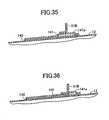
- FIGS. 32 to 36 show a sixth embodiment of the impact-absorbing steering column apparatus according to the present invention.
- collision-energy-absorbing means for absorbing secondary collision energy of the occupant H includes an energy-absorbing member 141 provided in the upper support mechanism A and an energy-absorbing member 143 provided in the lower support mechanism B.
- Structural features other than the collision-energy-absorbing means for absorbing secondary collision energy of the occupant H are substantially identical with those of the above-described first embodiment and are thus denoted by common reference numerals, and repeated description thereof is omitted.
- the energy-absorbing member 141 is an iron plate and plastically deformed when moving frontward while being engaged with the reinforcement plate 31 B of the support bracket 31 in the upper support mechanism A, thereby absorbing secondary collision energy.
- the energy-absorbing member 141 together with a base plate 142 formed of an iron plate, is welded to the upper surface of the steering column 12.
- the energy-absorbing member 141 includes a bulge portion 141 a bulging upward and extending from its intermediate portion to its rear end portion.
- the bulge portion 141a extends along the axial direction of the steering column 12 and can be engaged with a curved lower end portion of the reinforcement plate 31 B, which is bent to have an L-shaped cross section.
- the energy-absorbing member 143 provided in the lower support mechanism B is an elongated plate.
- the energy-absorbing member 143 is engaged with the collar 73 of the connection means 70 and plastically deformed to thereby absorb secondary collision energy.
- the energy-absorbing member 143 is fixedly attached, at its one end portion, to the column-side bracket 62 in the lower support mechanism B; loops around the collar 73; and extends frontward.
- the steering column 12 tilts upward at the initial stage of the secondary collision and subsequently moves frontward along its axial direction.
- the bulge portion 141 a of the upper energy-absorbing member 141 is engaged with the curved lower end portion of the reinforcement plate 31B of the support bracket 31 and moves frontward.
- the upper energy-absorbing member 141 may not be plastically deformed.
- the lower energy-absorbing member 143 is plastically deformed by means of the collar 73. Since secondary collision energy is absorbed by means of plastic deformation of only the energy-absorbing member 143 caused by the collar 73, an absorption load for secondary collision energy is small.
- the bulge portion 141 a of the upper energy-absorbing member 141 may be engaged with the curved lower end portion of the reinforcement plate 31 B of the support bracket 31.
- the energy-absorbing member 141 moves frontward while being plastically deformed. Since secondary collision energy is absorbed by means of plastic deformation of the energy-absorbing member 141 caused by the reinforcement plate 31B and plastic deformation of the energy-absorbing member 143 caused by the collar 73, an absorption load for secondary collision energy is larger than that in the case where the upward component of load is small. In this case, the quantity of plastic deformation of the energy-absorbing member 141 caused by the reinforcement member 31 B varies dependently on the upward component of the secondary collision load input to the steering column 12.
- energy-absorption-load-changing means including the energy-absorbing member 141 and the reinforcement plate 31B changes an absorption load for secondary collision energy in accordance with the direction and load of a secondary collision of the occupant H with the steering system.
- the sixth embodiment can be mechanically implemented by means of appropriately setting, for example, the shape of the bulge portion 141 a of the energy-absorbing member 141 and the shape and arrangement of the reinforcement plate 31 B, without need to employ electrical control, whose cost is high, and thus at low cost.
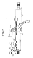
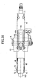
- FIGS. 37 to 42 show a seventh embodiment of the impact-absorbing steering column apparatus according to the present invention.
- collision-energy-absorbing means for absorbing secondary collision energy of the occupant H includes an energy-absorbing member 151 provided in the upper support mechanism A and an energy-absorbing member 153 provided in the lower support mechanism B.
- Structural features other than the collision-energy-absorbing means for absorbing secondary collision energy of the occupant H are substantially identical with those of the above-described first embodiment and are thus denoted by common reference numerals, and repeated description thereof is omitted.
- the energy-absorbing member 151 is an iron plate and plastically deformed when moving frontward while being engaged with the reinforcement plate 31 B of the support bracket 31 in the upper support mechanism A, thereby absorbing secondary collision energy.
- the energy-absorbing member 151 together with a base plate 152, is welded to the upper surface of the steering column 12.
- the energy-absorbing member 151 assumes an arcuate cross-sectional shape so as to be curved similarly to the outer circumference of the steering column 12 with a predetermined gap held therebetween.
- An upper surface of the energy-absorbing member 151 extending from its intermediate portion to its rear end portion can be engaged with a curved lower end portion of the reinforcement plate 31 B, which is bent to have an L-shaped cross section.
- the base plate 152 is an iron plate and adapted to form a space (a space that enables plastic deformation of the energy-absorbing member 151) between the steering column 12 and the energy-absorbing member 151.
- the base plate 152 assumes an arcuate cross-sectional shape so as to be curved similarly to the outer circumference of the steering column 12.
- the base plate 152 has a cutout that assumes a rectangular shape as viewed in plane. The cutout is formed in a region extending from an intermediate portion of the base plate 152 to a rear end portion of the base plate 152.
- the energy-absorbing member 153 provided in the lower support mechanism B is an elongated plate.
- the energy-absorbing member 153 is engaged with the collar 73 of the connection means 70 and plastically deformed to thereby absorb secondary collision energy.
- the energy-absorbing member 153 is fixedly attached, at its one end portion, to the column-side bracket 62 in the lower support mechanism B; loops around the collar 73; and extends frontward.
- the steering column 12 tilts upward at the initial stage of the secondary collision and subsequently moves frontward along its axial direction.
- the upper energy-absorbing member 151 is engaged with the curved lower end portion of the reinforcement plate 31 B of the support bracket 31 and moves frontward.
- the upper energy-absorbing member 151 may not be plastically deformed.
- the lower energy-absorbing member 153 is plastically deformed by means of the collar 73. Since secondary collision energy is absorbed by means of plastic deformation of only the energy-absorbing member 153 caused by the collar 73, an absorption load for secondary collision energy is small.
- energy-absorption-load-changing means including the energy-absorbing member 151 and the reinforcement plate 31 B changes an absorption load for secondary collision energy in accordance with the direction and load of a secondary collision of the occupant H with the steering system.
- the seventh embodiment can be mechanically implemented by means of appropriately setting, for example, the shape of the energy-absorbing member 151, the shape of the base plate 152, and the shape and arrangement of the reinforcement plate 31 B, without need to employ electrical control, whose cost is high, and thus at low cost.
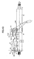
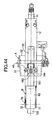
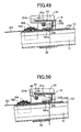
- FIGS. 43 to 50 show an eighth embodiment of the impact-absorbing steering column apparatus according to the present invention.
- collision-energy-absorbing means for absorbing secondary collision energy of the occupant H includes an energy-absorbing member 161 provided in the upper support mechanism A, a deformable portion 31 e provided in the plate 31A of the support bracket 31 in the upper support mechanism A, and an energy-absorbing member 165 provided in the lower support mechanism B.
- Structural features other than the collision-energy-absorbing means for absorbing secondary collision energy of the occupant H are substantially identical with those of the above-described first embodiment and are thus denoted by common reference numerals, and repeated description thereof is omitted.
- the energy-absorbing member 161 is a thin iron plate and squeeze-deformed when the steering column 12 moves frontward with the energy-absorbing member 161 being engaged with the reinforcement plate 31 B of the support bracket 31 in the upper support mechanism A, thereby absorbing secondary collision energy.
- the energy-absorbing member 161 is provided on the upper surface of the steering column 12 in such a manner as to be movable in the direction of the column axis, by use of a guide plate 162, a holder 163, and a round bar 164.
- the energy-absorbing member 161 has a projection 161 a projecting upward from its rear end portion. The projection 161a can be engaged with an engagement hole 31 formed in the reinforcement palate 31 B.
- the guide plate 162 is an iron plate and allows the energy-absorbing member 161 to move along the steering column 12 when the energy-absorbing member 161 is squeeze-deformed.
- the guide plate 162 is welded to the upper surface of the steering column 12.
- the holder 163 is an iron plate and causes squeeze-deformation of the energy-absorbing member 161 in cooperation with the round bar 164.
- the holder 163 is welded to an upper portion of the steering column 12 while straddling a portion of the energy-absorbing member 161 and a portion of the guide plate 162.
- the round bar 164 is made of iron and is incorporated in the holder 163 together with a portion of the energy-absorbing member 161.
- the deformable portion 31 e provided on the plate 31 A of the support bracket 31 in the upper support mechanism A is formed by means of forming in the plate 31A an elongated hole 31e1 extending in the front-rear direction.
- the deformable portion 31 e is plastically deformed upward, thereby allowing the projection 161 a of the energy-absorbing member 161 to be fitted into the engagement hole 31 f formed in the reinforcement plate 31 B.
- the energy-absorbing member 165 provided in the lower support mechanism B is an elongated plate.
- the energy-absorbing member 165 is engaged with the collar 73 of the connection means 70 and plastically deformed to thereby absorb secondary collision energy.
- the energy-absorbing member 165 is fixedly attached, at its one end portion, to the column-side bracket 62 in the lower support mechanism B; loops around the collar 73; and extends frontward.
- the steering column 12 tilts upward at the initial stage of the secondary collision and subsequently moves frontward along its axial direction.
- an upward component of the secondary collision load input to the steering column 12 is small, as shown in FIGS. 47 and 48 , the deformable portion 31e provided on the plate 31A of the support bracket 31 in the upper support mechanism A is not plastically deformed.
- the deformable portion 31e provided on the plate 31A of the support bracket 31 receives an upward load equal to or greater than a set value from the collar 42 and the lock bolt 41 of the clamp means 40 to thereby be plastically deformed upward.
- the projection 161a of the energy-absorbing member 161 is fitted into the engagement hole 31f formed in the reinforcement plate 31 B.
- the holder 163 and the round bar 164 squeeze-deforms the energy-absorbing member 161.
- the lower energy-absorbing member 165 is plastically deformed by means of the collar 73.
- energy-absorption-load-changing means including the energy-absorbing member 161, the guide plate 162, the holder 163, the round bar 164, and the support bracket 31 in the upper support mechanism A changes an absorption load for secondary collision energy in accordance with the direction and load of a secondary collision of the occupant H with the steering system.
- the eighth embodiment can be mechanically implemented by means of appropriately setting, for example, the shape of the projection 161a of the energy-absorbing member 161, the shape of the holder 163, the shape of the round bar 164, and the shape and arrangement of the support bracket 31 in the upper support mechanism A, without need to employ electrical control, whose cost is high, and thus at low cost.
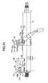
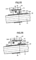
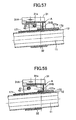
- FIGS. 51 to 58 show a ninth embodiment of the impact-absorbing steering column apparatus according to the present invention.
- collision-energy-absorbing means for absorbing secondary collision energy of the occupant H includes an energy-absorbing member 171 provided in the upper support mechanism A, the deformable portion 31 e provided in the plate 31 A of the support bracket 31 in the upper support mechanism A, and an energy-absorbing member 173 provided in the lower support mechanism B.
- Structural features other than the collision-energy-absorbing means for absorbing secondary collision energy of the occupant H are substantially identical with those of the above-described first embodiment and are thus denoted by common reference numerals, and repeated description thereof is omitted.
- the energy-absorbing member 171 is a thin iron plate and plastically deformed when moving frontward while being engaged with the reinforcement plate 31 B of the support bracket 31 in the upper support mechanism A, thereby absorbing secondary collision energy.
- the energy-absorbing member 171, together with a base plate 172, is welded to the upper surface of the steering column 12.
- the energy-absorbing member 171 includes a bulge portion 171 a bulging upward and extending from its intermediate portion to its rear end portion.
- the bulge portion 171a extends along the axial direction of the steering column 12 and can be engaged with a curved lower end portion of the reinforcement plate 31 B, which is bent to have an L-shaped cross section.
- the deformable portion 31 e provided on the plate 31A of the support bracket 31 in the upper support mechanism A is formed by means of forming in the plate 31A the elongated hole 31e1 extending in the front-rear direction.
- the deformable portion 31 e receives an upward load equal to or greater than a set value from the collar 42 and the lock bolt 41 of the clamp means 40, the deformable portion 31e is plastically deformed upward, thereby allowing the bulge portion 171a of the energy-absorbing member 171 to be engaged with the curved lower end portion of the reinforcement plate 31B.
- the energy-absorbing member 173 provided in the lower support mechanism B is an elongated plate.
- the energy-absorbing member 173 is engaged with the collar 73 of the connection means 70 and plastically deformed to thereby absorb secondary collision energy.
- the energy-absorbing member 173 is fixedly attached, at its one end portion, to the column-side bracket 62 in the lower support mechanism B; loops around the collar 73; and extends frontward.
- the steering column 12 tilts upward at the initial stage of the secondary collision and subsequently moves frontward along its axial direction.
- the deformable portion 31 e provided on the plate 31 A of the support bracket 31 in the upper support mechanism A is not plastically deformed; and the bulge portion 171 a of the upper energy-absorbing member 171 is engaged with the curved lower end portion of the reinforcement plate 31 B of the support bracket 31, but is not plastically deformed.
- the lower energy-absorbing member 173 is plastically deformed by means of the collar 73. Since secondary collision energy is absorbed by means of plastic deformation of only the energy-absorbing member 173 caused by the collar 73, an absorption load for secondary collision energy is small.
- the deformable portion 31 e provided on the plate 31A of the support bracket 31 receives an upward load equal to or greater than a set value from the collar 42 and the lock bolt 41 of the clamp means 40 to thereby be plastically deformed upward.
- the bulge portion 171a of the upper energy-absorbing member 171 is engaged with the curved lower end portion of the reinforcement plate 31 B of the support bracket 31.
- the bulge portion 171 a of the upper energy-absorbing member 171 is plastically deformed by means of the reinforcement plate 31 B of the support bracket 31.
- the lower energy-absorbing member 173 is plastically deformed by means of the collar 73.
- energy-absorption-load-changing means including the energy-absorbing member 171 and the support bracket 31 in the upper support mechanism A changes an absorption load for secondary collision energy in accordance with the direction and load of a secondary collision of the occupant H with the steering system.
- the ninth embodiment can be mechanically implemented by means of appropriately setting, for example, the shape of the bulge portion 171 a of the energy-absorbing member 171 and the shape and arrangement of the support bracket 31 in the upper support mechanism A, without need to employ electrical control, whose cost is high, and thus at low cost.
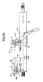
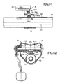
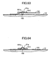
- FIGS. 59 to 64 show a tenth embodiment of the impact-absorbing steering column apparatus according to the present invention.
- collision-energy-absorbing means for absorbing secondary collision energy of the occupant H includes an energy-absorbing member 181 provided in the upper support mechanism A, squeezing plate 31C provided on the reinforcement plate 31B of the support bracket 31 in the upper support mechanism A, and an energy-absorbing member 183 provided in the lower support mechanism B.
- Structural features other than the collision-energy-absorbing means for absorbing secondary collision energy of the occupant H are substantially identical with those of the above-described first embodiment and are thus denoted by common reference numerals, and repeated description thereof is omitted.
- the energy-absorbing member 181 is a thin iron plate and squeeze-deformed when the steering column 12 moves frontward with the energy-absorbing member 181 being engaged with the squeezing plate 31C provided on the reinforcement plate 31B of the support bracket 31 in the upper support mechanism A, thereby absorbing secondary collision energy.
- the energy-absorbing member 181 is welded, at its front end portion, to the upper surface of the steering column 12.
- the energy-absorbing member 181 includes a curved portion 181 a located in its axially intermediate region, curved upward, and adapted to accommodate a round bar 182, and laterally paired arm portions 181b for restricting lateral movement of the round bar 182.
- the curved portion 181a which accommodates the round bar 182, can be engaged with an engagement hole 31g formed in the squeezing plate 31C by means of being fitted into the engagement hole 31g.
- the squeezing plate 31C provided on the reinforcement plate 31B of the support bracket 31 in the upper support mechanism A is an iron plate and causes squeeze-deformation of the energy-absorbing member 181 in cooperation with the round bar 182.
- the squeezing plate 31C is welded to the lower surface of the reinforcement plate 31B.
- the round bar 182 is a solid iron rod; is incorporated in the curved portion 181 a of the energy-absorbing member 181; and is movable along the upper surface of the steering column 12 in the direction of the column axis.
- the energy-absorbing member 183 provided in the lower support mechanism B is an elongated plate.
- the energy-absorbing member 183 is engaged with the collar 73 of the connection means 70 and plastically deformed to thereby absorb secondary collision energy.
- the energy-absorbing member 183 is fixedly attached, at its one end portion, to the column-side bracket 62 in the lower support mechanism B; loops around the collar 73; and extends frontward.
- the steering column 12 tilts upward at the initial stage of the secondary collision and subsequently moves frontward along its axial direction.
- an upward component of the secondary collision load input to the steering column 12 is small, as shown in FIG.
- energy-absorption-load-changing means including the energy-absorbing member 181, the round bar 182, and the squeezing plate 31C provided on the reinforcement plate 31B of the support bracket 31 in the upper support mechanism A changes an absorption load for secondary collision energy in accordance with the direction and load of a secondary collision of the occupant H with the steering system.
- the tenth embodiment can be mechanically implemented by means of appropriately setting, for example, the shape of the energy-absorbing member 181, the shape of the round bar 182, and the shape and arrangement of the squeezing plate 31C provided on the reinforcement plate 31 B of the support bracket 31 in the upper support mechanism A, without need to employ electrical control, whose cost is high, and thus at low cost.
Landscapes
- Engineering & Computer Science (AREA)
- Mechanical Engineering (AREA)
- Chemical & Material Sciences (AREA)
- Combustion & Propulsion (AREA)
- Transportation (AREA)
- General Engineering & Computer Science (AREA)
- Steering Controls (AREA)
Claims (24)
- Appareil de colonne de direction à absorption de chocs comprenant un moyen (41, 42, 36, 37) d'absorption d'une énergie de collision pour absorber une énergie de collision secondaire d'un occupant (H) en cas d'une collision d'un véhicule, le moyen (41, 42, 36, 37) d'absorption d'une énergie de collision comprenant un moyen (41, 42, 36, 37) de changement d'un effort d'absorption d'énergie pour changer un effort d'absorption pour l'énergie de collision secondaire,
caractérisé en ce que
le moyen (41, 42, 36, 37) de changement d'un effort d'absorption d'énergie est adapté pour changer l'effort d'absorption suivant un déplacement d'une colonne de direction (12) dans au moins une première direction le long d'un premier guide (31a1, 31b1), lorsqu'une collision secondaire de l'occupant (H) avec la colonne de direction (12) se produit dans une première direction, et dans une deuxième direction le long d'un deuxième guide (31a2, 31 b2), lorsque la collision secondaire de l'occupant (H) avec la colonne de direction (12) se produit dans une deuxième direction. - Appareil de colonne de direction à absorption de chocs selon la revendication 1, dans lequel le moyen (41, 42, 36, 37) de changement d'un effort d'absorption d'énergie change l'effort d'absorption suivant une direction de l'énergie de collision secondaire.
- Appareil de colonne de direction à absorption de chocs selon la revendication 2, dans lequel le moyen (41, 42, 36, 37) de changement d'un effort d'absorption d'énergie comprend un organe (36, 37) d'absorption d'énergie, et un moyen d'engagement (41, 42) capable de s'engager avec l'organe (36, 37) d'absorption d'énergie, et une relation d'engagement entre l'organe (36, 37) d'absorption d'énergie et le moyen d'engagement (41, 42) varie suivant une direction de l'énergie de collision secondaire, changeant ainsi l'effort d'absorption.
- Appareil de colonne de direction à absorption de chocs selon la revendication 3, dans lequel le moyen d'engagement (41, 42) est un moyen de compression (41, 42) pour comprimer l'organe (36, 37) d'absorption d'énergie; l'organe (36, 37) d'absorption d'énergie possède une partie (36, 37) d'absorption d'énergie, qui est comprimée par le moyen de compression (41, 42) pour absorber ainsi l'énergie; et une relation d'engagement entre le moyen de compression (41, 42) et la partie (36, 37) d'absorption d'énergie varie suivant une direction de l'énergie de collision secondaire, changeant ainsi l'effort d'absorption.
- Appareil de colonne de direction à absorption de chocs selon la revendication 3, dans lequel le moyen d'engagement (41, 42) est un moyen de compression (41, 42) pour comprimer l'organe (36, 37) d'absorption d'énergie; l'organe (36, 37) d'absorption d'énergie a une pluralité de parties (36, 37) d'absorption d'énergie qui comprennent différentes caractéristiques d'absorption par déformation en relation avec le moyen de compression (41, 42); et une relation d'engagement entre le moyen de compression (41, 42) et l'une de la pluralité de parties (36, 37) d'absorption d'énergie est sélectionnée suivant une direction de l'énergie de collision secondaire, changeant ainsi l'effort d'absorption.
- Appareil de colonne de direction à absorption de chocs selon la revendication 3, dans lequel le moyen d'engagement (41, 42) est un moyen de compression (41, 42) pour comprimer l'organe (36, 37) d'absorption d'énergie; le moyen de compression a une pluralité de parties de compression (41, 42) qui sont différentes en termes de quantité de compression lors de la compression de l'organe (36, 37) d'absorption d'énergie; et une relation d'engagement entre l'organe (36, 37) d'absorption d'énergie et l'une de la pluralité de parties de compression (41, 42) est sélectionnée suivant une direction de l'énergie de collision secondaire, changeant ainsi l'effort d'absorption.
- Appareil de colonne de direction à absorption de chocs selon la revendication 3, dans lequel l'organe d'absorption d'énergie est un organe linéaire capable de s'engager avec le moyen d'engagement; le moyen d'engagement est engagé avec l'organe linéaire, ou n'est pas engagé avec ce dernier, suivant une direction de l'énergie de collision secondaire, changeant ainsi l'effort d'absorption.
- Appareil de colonne de direction à absorption de chocs selon la revendication 3, dans lequel l'organe d'absorption d'énergie est une pluralité d'organes linéaires capables de s'engager avec le moyen d'engagement; le nombre des organes linéaires devant s'engager avec le moyen d'engagement varie suivant une direction de l'énergie de collision secondaire, changeant ainsi l'effort d'absorption.
- Appareil de colonne de direction à absorption de chocs selon la revendication 3, dans lequel la colonne de direction (12) comprend l'organe d'absorption d'énergie, une bille adaptée pour déformer plastiquement l'organe d'absorption d'énergie, et un moyen de soutien de la bille pour ajuster la quantité de déformation plastique que la bille va mettre en oeuvre; et le moyen de soutien de la bille est déplacé suivant une direction de l'énergie de collision secondaire de sorte à faire varier une relation d'engagement entre l'organe d'absorption d'énergie et la bille suivant la direction, changeant ainsi l'effort d'absorption.
- Appareil de colonne de direction à absorption de chocs selon la revendication 3, dans lequel l'organe d'absorption d'énergie à une rainure allongée ayant une largeur prédéterminée; le moyen d'engagement est un moyen de compression prenant une forme spéciale et pouvant être déplacé dans la rainure allongée en relation avec l'organe d'absorption d'énergie; et une relation d'engagement entre le moyen de compression à forme spéciale et la rainure allongée de l'organe d'absorption d'énergie varie suivant une direction de l'énergie de collision secondaire, changeant ainsi l'effort d'absorption.
- Appareil de colonne de direction à absorption de chocs selon la revendication 3, dans lequel l'organe d'absorption d'énergie est prévu soit sur un organe côté carrosserie d'un véhicule ou sur la colonne de direction (12), l'organe d'absorption d'énergie générant un effort d'absorption d'énergie au moyen d'un déplacement en relation soit avec l'organe côté carrosserie d'un véhicule ou avec la colonne de direction (12) sur laquelle l'organe d'absorption d'énergie est prévu; le moyen d'engagement capable de s'engager avec l'organe d'absorption d'énergie est prévu soit sur l'organe côté carrosserie d'un véhicule pour sur la colonne de direction (12) sur laquelle l'organe d'absorption d'énergie n'est pas prévu; et lorsque l'organe d'absorption d'énergie est engagé avec le moyen d'engagement suivant une direction de l'énergie de collision secondaire, la direction de l'énergie de collision secondaire changeant en fonction d'une collision secondaire, l'organe d'absorption d'énergie change de manière incrémentielle l'effort d'absorption au moyen d'un déplacement en relation soit avec l'organe côté carrosserie d'un véhicule ou avec la colonne de direction (12) sur laquelle l'organe d'absorption d'énergie est prévu.
- Appareil de colonne de direction à absorption de chocs selon l'une quelconque des revendications 1 à 11, dans lequel le moyen (41, 42, 36, 37) de changement d'un effort d'absorption d'énergie change l'effort d'absorption suivant un déplacement de la colonne de direction (12), le déplacement changeant en fonction de la direction d'une collision secondaire de l'occupant (H) avec le système de direction.
- Appareil de colonne de direction à absorption de chocs selon l'une quelconque des revendications 1 à 12, dans lequel le moyen (41, 42, 36, 37) de changement d'un effort d'absorption d'énergie change l'effort d'absorption suivant un déplacement de la colonne de direction (12), le déplacement changeant en fonction de la direction d'une collision secondaire de l'occupant (H) avec le système de direction au niveau d'une phase initiale de la collision secondaire.
- Appareil de colonne de direction à absorption de chocs selon l'une quelconque des revendications 1 à 13, dans lequel, lorsqu'une charge de collision associée à une collision secondaire de l'occupant (H) avec le système de direction est supérieure ou égale à une valeur prédéterminée, le moyen (41, 42, 36, 37) de changement d'un effort d'absorption d'énergie accroît l'effort d'absorption.
- Appareil de colonne de direction à absorption de chocs selon l'une quelconque des revendications 1 à 14, dans lequel le moyen (41, 42, 36, 37) de changement d'un effort d'absorption d'énergie accroît l'effort d'absorption suivant un déplacement tel que la colonne de direction (12) s'incline vers le haut comme un résultat d'une collision secondaire de l'occupant (H) avec le système de direction.
- Appareil de colonne de direction à absorption de chocs selon l'une quelconque des revendications 1 à 15, dans lequel le moyen (41, 42, 36, 37) de changement d'un effort d'absorption d'énergie change l'effort d'absorption suivant une position déplacée de la colonne de direction (12), la position déplacée changeant en fonction de la direction d'une collision secondaire de l'occupant (H) avec le système de direction.
- Appareil de colonne de direction à absorption de chocs selon l'une quelconque des revendications 1 à 16, dans lequel un moyen d'absorption de chocs pour absorber une charge de collision prédéterminée est prévu séparément du moyen (41, 42, 36, 37) d'absorption d'une énergie de collision.
- Appareil de colonne de direction à absorption de chocs selon l'une quelconque des revendications 1 à 17, dans lequel le moyen (41, 42, 36, 37) d'absorption d'une énergie de collision produit, au choix, l'effort d'absorption, ou change la grandeur de l'effort d'absorption.
- Appareil de colonne de direction à absorption de chocs selon la revendication 1, dans lequel, en accord avec une charge appuyant la colonne de direction (12) contre un organe côté carrosserie d'un véhicule et une charge déplaçant la colonne de direction (12) vers la partie avant du véhicule, les charges changeant en fonction d'une collision secondaire de l'occupant (H) avec le système de direction, une déformation d'un organe (36, 37) d'absorption d'énergie prévu soit sur la colonne de direction (12) ou sur l'organe côté carrosserie du véhicule est changée passivement par un moyen d'engagement (41, 42) prévu soit sur la colonne de direction (12) ou sur l'organe côté carrosserie du véhicule sur lequel l'organe (36, 37) d'absorption d'énergie n'est pas prévu, de sorte que le moyen (41, 42, 36, 37) de changement d'un effort d'absorption d'énergie change l'effort d'absorption.
- Appareil de colonne de direction à absorption de chocs selon la revendication 19, dans lequel le moyen d'engagement (41, 42) est formé sur l'organe côté carrosserie d'un véhicule; l'organe (36, 37) d'absorption d'énergie est prévu sur la colonne de direction (12) en opposition au moyen d'engagement (41, 42) et adopte une forme allongée s'étendant le long d'un axe de la colonne de direction (12); et le moyen d'engagement (41, 42) prévu sur l'organe côté carrosserie d'un véhicule provoque la déformation de l'organe (36, 37) d'absorption d'énergie prévu sur la colonne de direction (12).
- Appareil de colonne de direction à absorption de chocs selon la revendication 19 ou 20, dans lequel un aboutement entre le moyen d'engagement (41, 42) et l'organe (36, 37) d'absorption d'énergie n'est permis que lorsqu'une charge de collision imposée sur l'organe côté carrosserie d'un véhicule depuis la colonne de direction (12) est supérieure ou égale à une valeur prédéterminée.
- Appareil de colonne de direction à absorption de chocs selon l'une quelconque des revendications 1 à 21, dans lequel dans le cas d'une collision secondaire, la colonne de direction (12) est habilitée à être déplacée de sorte à s'incliner vers un organe côté carrosserie d'un véhicule.
- Appareil de colonne de direction à absorption de chocs selon l'une quelconque des revendications 1 à 22, dans lequel l'effort d'absorption est augmenté avec une charge d'appui de la colonne de direction (12) contre un organe côté carrosserie d'un véhicule.
- Appareil de colonne de direction à absorption de chocs selon l'une quelconque des revendications 1 à 23, dans lequel un moyen d'absorption de chocs pour absorber une charge de collision prédéterminée est prévu séparément du moyen (41, 42, 36, 37) d'absorption d'une énergie de collision.
Applications Claiming Priority (5)
| Application Number | Priority Date | Filing Date | Title |
|---|---|---|---|
| JP2002293237 | 2002-10-07 | ||
| JP2002293237 | 2002-10-07 | ||
| JP2003137823 | 2003-05-15 | ||
| JP2003137823A JP4124021B2 (ja) | 2002-10-07 | 2003-05-15 | 衝撃吸収式ステアリングコラム装置 |
| PCT/JP2003/010417 WO2004031020A1 (fr) | 2002-10-07 | 2003-08-19 | Dispositif de colonne de direction a absorption d'energie de collision |
Publications (3)
| Publication Number | Publication Date |
|---|---|
| EP1550599A1 EP1550599A1 (fr) | 2005-07-06 |
| EP1550599A4 EP1550599A4 (fr) | 2007-01-03 |
| EP1550599B1 true EP1550599B1 (fr) | 2010-03-03 |
Family
ID=32072499
Family Applications (1)
| Application Number | Title | Priority Date | Filing Date |
|---|---|---|---|
| EP03799083A Expired - Lifetime EP1550599B1 (fr) | 2002-10-07 | 2003-08-19 | Dispositif de colonne de direction a absorption d'energie de collision |
Country Status (5)
| Country | Link |
|---|---|
| US (1) | US7240922B2 (fr) |
| EP (1) | EP1550599B1 (fr) |
| JP (1) | JP4124021B2 (fr) |
| DE (1) | DE60331568D1 (fr) |
| WO (1) | WO2004031020A1 (fr) |
Families Citing this family (16)
| Publication number | Priority date | Publication date | Assignee | Title |
|---|---|---|---|---|
| JP2003327133A (ja) | 2002-05-13 | 2003-11-19 | Koyo Seiko Co Ltd | ステアリング装置 |
| AU2003246136A1 (en) * | 2002-07-02 | 2004-01-23 | Nsk Ltd. | Shock absorbing steering column device for vehicle |
| JP2004203164A (ja) * | 2002-12-25 | 2004-07-22 | Fuji Kiko Co Ltd | 車両用ステアリング装置の衝撃吸収構造 |
| US7334817B2 (en) | 2004-09-02 | 2008-02-26 | Delphi Technologies, Inc. | Active energy absorption method using tilt and telescope positions |
| JP5328116B2 (ja) * | 2007-07-19 | 2013-10-30 | テイ・エス テック株式会社 | シートフレーム及び車両用シート |
| JP5120115B2 (ja) * | 2008-07-04 | 2013-01-16 | 日本精工株式会社 | ステアリングコラムの支持装置 |
| DE102010020088B4 (de) * | 2010-05-10 | 2013-06-27 | Thyssenkrupp Presta Aktiengesellschaft | Verfahren und Vorrichtung zur Regelung eines steuerbaren Energieabsorbers |
| EP2565103B1 (fr) | 2010-06-16 | 2015-04-01 | NSK Ltd. | Support de colonne de direction |
| JP5499995B2 (ja) * | 2010-08-26 | 2014-05-21 | 日本精工株式会社 | 電動式パワーステアリング装置を備えた衝撃吸収式ステアリング装置 |
| JP5321634B2 (ja) * | 2011-04-01 | 2013-10-23 | 日本精工株式会社 | 自動車用ステアリングコラムの支持装置 |
| JP5874361B2 (ja) * | 2011-12-05 | 2016-03-02 | 日本精工株式会社 | ステアリング装置の製造方法 |
| JP5949281B2 (ja) * | 2012-07-27 | 2016-07-06 | 株式会社ジェイテクト | 車両用ステアリング装置 |
| EP2915719B1 (fr) * | 2012-11-02 | 2018-07-11 | NSK Ltd. | Dispositif de conduite de type à inclinaison |
| DE102014110204B3 (de) * | 2014-07-21 | 2015-10-01 | Thyssenkrupp Presta Ag | Lenksäule für ein Kraftfahrzeug |
| DE102019124824A1 (de) * | 2019-09-16 | 2021-03-18 | Thyssenkrupp Ag | Lenksäule für ein Kraftfahrzeug und Baugruppe mit einer solchen sowie Kraftfahrzeug mit einer solchen |
| CN110758547B (zh) * | 2019-11-04 | 2023-11-14 | 长安大学 | 一种基于负泊松比结构的溃缩式汽车转向装置 |
Family Cites Families (27)
| Publication number | Priority date | Publication date | Assignee | Title |
|---|---|---|---|---|
| US3392599A (en) * | 1966-12-30 | 1968-07-16 | Gen Motors Corp | Energy absorbing device |
| JPS5141700Y2 (fr) * | 1972-09-28 | 1976-10-09 | ||
| JPS4968127A (fr) | 1972-11-10 | 1974-07-02 | ||
| GB1497275A (en) | 1975-08-22 | 1978-01-05 | Imp Metal Ind Kynoch Ltd | Steering columns |
| US5259818A (en) * | 1989-04-14 | 1993-11-09 | Fuji Kiko Company, Limited | Stroke absorbing type intermediate shaft for vehicular steering column and method for assembling the same |
| US4989898A (en) * | 1989-09-07 | 1991-02-05 | Nippon Seiko Kabushiki Kaisha | Energy absorption type steering apparatus |
| FR2708551B1 (fr) | 1993-08-06 | 1995-10-20 | Nacam | Colonne de direction à carré renfort à amortissement axial. |
| FR2713188B1 (fr) | 1993-11-29 | 1996-02-23 | Nacam | Dispositif d'absorption d'énergie pour colonne de direction de véhicule automobile. |
| US5961146A (en) * | 1996-01-18 | 1999-10-05 | Nsk Ltd. | Shock absorbing type steering column assembly |
| KR100205854B1 (ko) * | 1996-04-30 | 1999-07-01 | 오상수 | 차량용 스티어링 샤프트 에너지 흡수장치 |
| JP3612971B2 (ja) | 1997-12-03 | 2005-01-26 | 日本精工株式会社 | 衝撃吸収式ステアリングコラム装置 |
| FR2775646B1 (fr) * | 1998-03-03 | 2000-05-12 | Lemforder Nacam Sa | Dispositif d'absorption d'energie a double enroulement pour colonne de direction de vehicule automobile |
| FR2788029B1 (fr) * | 1999-01-06 | 2001-02-23 | Lemforder Nacam Sa | Dispositif d'absorption modulable d'energie d'une colonne de direction de vehicule automobile |
| EP1192072B1 (fr) | 1999-06-11 | 2003-11-26 | Delphi Technologies, Inc. | Amortisseur pour colonnes directrices de vehicules motorises |
| US6189929B1 (en) * | 1999-11-02 | 2001-02-20 | Trw Inc. | Adaptive collapsible steering column |
| JP2001278071A (ja) * | 2000-03-30 | 2001-10-10 | Nsk Ltd | ステアリングコラムの支持装置 |
| JP2002067980A (ja) * | 2000-09-04 | 2002-03-08 | Nsk Ltd | 衝撃吸収式ステアリングコラム装置 |
| US6726248B2 (en) | 2000-05-16 | 2004-04-27 | Nsk Ltd. | Impact absorbing type steering column apparatus |
| JP4470299B2 (ja) * | 2000-08-29 | 2010-06-02 | 日本精工株式会社 | 衝撃吸収式ステアリングコラム装置 |
| JP2002067979A (ja) * | 2000-08-31 | 2002-03-08 | Nsk Ltd | 衝撃吸収式ステアリングコラム装置 |
| JP2002079944A (ja) | 2000-09-08 | 2002-03-19 | Nsk Ltd | 衝撃吸収式ステアリングコラム装置 |
| US6581966B2 (en) * | 2001-01-05 | 2003-06-24 | Ford Global Technologies, Inc. | Twin axis steering wheel system |
| JP2002284017A (ja) * | 2001-03-23 | 2002-10-03 | Nsk Ltd | 衝撃吸収式ステアリングコラム装置 |
| JP3900924B2 (ja) | 2001-04-03 | 2007-04-04 | トヨタ自動車株式会社 | ステアリング装置の支持機構 |
| US6659504B2 (en) * | 2001-05-18 | 2003-12-09 | Delphi Technologies, Inc. | Steering column for a vehicle |
| JP2003276544A (ja) | 2002-03-20 | 2003-10-02 | Toyota Motor Corp | 乗員保護装置 |
| US6729648B2 (en) * | 2002-06-07 | 2004-05-04 | Sealy Technology Llc | Non-linear energy absorbing column assembly |
-
2003
- 2003-05-15 JP JP2003137823A patent/JP4124021B2/ja not_active Expired - Fee Related
- 2003-08-19 WO PCT/JP2003/010417 patent/WO2004031020A1/fr not_active Ceased
- 2003-08-19 US US10/511,303 patent/US7240922B2/en not_active Expired - Fee Related
- 2003-08-19 EP EP03799083A patent/EP1550599B1/fr not_active Expired - Lifetime
- 2003-08-19 DE DE60331568T patent/DE60331568D1/de not_active Expired - Lifetime
Also Published As
| Publication number | Publication date |
|---|---|
| US20050173912A1 (en) | 2005-08-11 |
| US7240922B2 (en) | 2007-07-10 |
| EP1550599A1 (fr) | 2005-07-06 |
| JP4124021B2 (ja) | 2008-07-23 |
| WO2004031020A1 (fr) | 2004-04-15 |
| JP2004182216A (ja) | 2004-07-02 |
| DE60331568D1 (de) | 2010-04-15 |
| EP1550599A4 (fr) | 2007-01-03 |
Similar Documents
| Publication | Publication Date | Title |
|---|---|---|
| EP1550599B1 (fr) | Dispositif de colonne de direction a absorption d'energie de collision | |
| EP1395479B1 (fr) | Colonne de direction amelioree pour un vehicule | |
| US8919220B2 (en) | Steering column apparatus | |
| US7311333B2 (en) | Vehicle shock absorption type steering column device | |
| US20030164608A1 (en) | Automotive steering system | |
| US20030209102A1 (en) | Vehicular steering apparatus | |
| EP1518775B1 (fr) | Dispositif de colonne de guidage a absorption de choc pour vehicule | |
| JP7688524B2 (ja) | ステアリング装置 | |
| JPH092294A (ja) | 位置調節式ステアリング装置 | |
| WO2023038013A1 (fr) | Dispositif de colonne de direction | |
| KR20010022716A (ko) | 스티어링 조립체 | |
| US5452917A (en) | Apparatus for supporting a tiltable steering shaft | |
| JP4207799B2 (ja) | 衝撃吸収式ステアリングコラム装置 | |
| JP7688525B2 (ja) | ステアリング装置 | |
| EP1600355B1 (fr) | Dispositif de direction rétractable | |
| JP2010012980A (ja) | 衝撃吸収式ステアリングコラム装置 | |
| KR20140065844A (ko) | 자동차의 스티어링 컬럼 장치 | |
| JP3838018B2 (ja) | 車両用ステアリングコラム構造 | |
| JP7824815B2 (ja) | ステアリング装置 | |
| EP1919755B1 (fr) | Ensemble colonne de direction | |
| KR101702241B1 (ko) | 자동차의 조향컬럼 | |
| JP7747657B2 (ja) | ステアリング装置 | |
| JP2008260358A (ja) | 衝撃吸収式ステアリングコラム装置 | |
| KR19990037985U (ko) | 스트랩을 이용한 조향컬럼의 충격흡수 장치 | |
| JP3914772B2 (ja) | 衝撃吸収ステアリング装置 |
Legal Events
| Date | Code | Title | Description |
|---|---|---|---|
| PUAI | Public reference made under article 153(3) epc to a published international application that has entered the european phase |
Free format text: ORIGINAL CODE: 0009012 |
|
| 17P | Request for examination filed |
Effective date: 20041020 |
|
| AK | Designated contracting states |
Kind code of ref document: A1 Designated state(s): AT BE BG CH CY CZ DE DK EE ES FI FR GB GR HU IE IT LI LU MC NL PT RO SE SI SK TR |
|
| RBV | Designated contracting states (corrected) |
Designated state(s): DE FR GB |
|
| A4 | Supplementary search report drawn up and despatched |
Effective date: 20061206 |
|
| 17Q | First examination report despatched |
Effective date: 20070723 |
|
| GRAP | Despatch of communication of intention to grant a patent |
Free format text: ORIGINAL CODE: EPIDOSNIGR1 |
|
| GRAS | Grant fee paid |
Free format text: ORIGINAL CODE: EPIDOSNIGR3 |
|
| GRAA | (expected) grant |
Free format text: ORIGINAL CODE: 0009210 |
|
| AK | Designated contracting states |
Kind code of ref document: B1 Designated state(s): DE FR GB |
|
| REG | Reference to a national code |
Ref country code: GB Ref legal event code: FG4D |
|
| REF | Corresponds to: |
Ref document number: 60331568 Country of ref document: DE Date of ref document: 20100415 Kind code of ref document: P |
|
| PGFP | Annual fee paid to national office [announced via postgrant information from national office to epo] |
Ref country code: FR Payment date: 20100824 Year of fee payment: 8 Ref country code: DE Payment date: 20100812 Year of fee payment: 8 |
|
| PGFP | Annual fee paid to national office [announced via postgrant information from national office to epo] |
Ref country code: GB Payment date: 20100818 Year of fee payment: 8 |
|
| PLBE | No opposition filed within time limit |
Free format text: ORIGINAL CODE: 0009261 |
|
| STAA | Information on the status of an ep patent application or granted ep patent |
Free format text: STATUS: NO OPPOSITION FILED WITHIN TIME LIMIT |
|
| 26N | No opposition filed |
Effective date: 20101206 |
|
| GBPC | Gb: european patent ceased through non-payment of renewal fee |
Effective date: 20110819 |
|
| REG | Reference to a national code |
Ref country code: FR Ref legal event code: ST Effective date: 20120430 |
|
| REG | Reference to a national code |
Ref country code: DE Ref legal event code: R119 Ref document number: 60331568 Country of ref document: DE Effective date: 20120301 |
|
| PG25 | Lapsed in a contracting state [announced via postgrant information from national office to epo] |
Ref country code: GB Free format text: LAPSE BECAUSE OF NON-PAYMENT OF DUE FEES Effective date: 20110819 Ref country code: FR Free format text: LAPSE BECAUSE OF NON-PAYMENT OF DUE FEES Effective date: 20110831 |
|
| PG25 | Lapsed in a contracting state [announced via postgrant information from national office to epo] |
Ref country code: DE Free format text: LAPSE BECAUSE OF NON-PAYMENT OF DUE FEES Effective date: 20120301 |