EP1551068A1 - Tragbares elektronisches gerät - Google Patents
Tragbares elektronisches gerät Download PDFInfo
- Publication number
- EP1551068A1 EP1551068A1 EP02807981A EP02807981A EP1551068A1 EP 1551068 A1 EP1551068 A1 EP 1551068A1 EP 02807981 A EP02807981 A EP 02807981A EP 02807981 A EP02807981 A EP 02807981A EP 1551068 A1 EP1551068 A1 EP 1551068A1
- Authority
- EP
- European Patent Office
- Prior art keywords
- battery pack
- portions
- battery
- battery chamber
- faces
- Prior art date
- Legal status (The legal status is an assumption and is not a legal conclusion. Google has not performed a legal analysis and makes no representation as to the accuracy of the status listed.)
- Withdrawn
Links
Images



Classifications
-
- H—ELECTRICITY
- H04—ELECTRIC COMMUNICATION TECHNIQUE
- H04M—TELEPHONIC COMMUNICATION
- H04M1/00—Substation equipment, e.g. for use by subscribers
- H04M1/02—Constructional features of telephone sets
- H04M1/0202—Portable telephone sets, e.g. cordless phones, mobile phones or bar type handsets
- H04M1/026—Details of the structure or mounting of specific components
- H04M1/0262—Details of the structure or mounting of specific components for a battery compartment
-
- Y—GENERAL TAGGING OF NEW TECHNOLOGICAL DEVELOPMENTS; GENERAL TAGGING OF CROSS-SECTIONAL TECHNOLOGIES SPANNING OVER SEVERAL SECTIONS OF THE IPC; TECHNICAL SUBJECTS COVERED BY FORMER USPC CROSS-REFERENCE ART COLLECTIONS [XRACs] AND DIGESTS
- Y02—TECHNOLOGIES OR APPLICATIONS FOR MITIGATION OR ADAPTATION AGAINST CLIMATE CHANGE
- Y02E—REDUCTION OF GREENHOUSE GAS [GHG] EMISSIONS, RELATED TO ENERGY GENERATION, TRANSMISSION OR DISTRIBUTION
- Y02E60/00—Enabling technologies; Technologies with a potential or indirect contribution to GHG emissions mitigation
- Y02E60/10—Energy storage using batteries
Definitions
- the present invention relates to a mobile electronic apparatus having a removable battery pack and, more particularly, to a mobile electronic apparatus which can realize a smooth loading of the battery pack.
- a mobile telephone generally used a removable battery pack for its power source.
- This battery pack is usually formed into a thin plate shape so that it is loaded into a battery chamber formed in the lower portion of the back of the body casing of the mobile telephone.
- a conventional mobile telephone such as a rod-shaped (or straight type) mobile telephone and its battery pack are specifically described with reference to Fig. 17.
- a casing 101 on the side of a body 100 of the mobile telephone is formed generally into a box shape.
- a battery chamber 102 which is provided on its floor face side with a plurality of spring terminals 103.
- These spring terminals 103 are disposed in the widthwise (X) direction for electric contact to a later-described battery pack 200.
- the battery pack 200 has a body portion 201 formed into a thin box- or plate-shape, and is provided back electrodes 202 at the portion corresponding to the disposed position of the sprint terminals 103 of the battery chamber 102, i.e., at the upper end portion of the back face portion.
- the battery pack 200 is provided in the battery chamber 102 with a pair of left and right push-up projections 104 for preventing the back side of the battery pack 200 from coming into forcible contact with the spring terminals 103 in the battery chamber 102 when the battery pack 200 is loaded into the battery chamber 102.
- the battery pack 200 is provided, on the two sides of one end portion (or the leading end side) on its back, with riding projections 203 for engaging with those push-up projections 104.
- the riding projections 203 on the battery pack 200 ride over the push-up projections 104 on the side of the battery chamber 102, thereby to prevent the back of the battery pack 200 from contacting with the spring terminals 103 on the side of the battery chamber 102.
- the push-up projections 104 on the side of the battery chamber 102 and the riding projections 203 on the side of the battery pack 200 are formed generally into a square pole shape.
- the battery pack 200 performs such a riding action that its leading end portion having the riding projections 203 are once pushed up generally in the upward (Z) direction by the push-up projections 104 and then abruptly fall down just after they passed the spring terminals 103.
- the battery pack 200 makes such straight motions, in which it abruptly falls down at a substantially right angle of about 90 degrees to the floor face of the battery chamber 102 so that the loading action of the battery pack 200 cannot be kept away from any rattling.
- the battery pack 200 is loaded while its back sliding on the spring terminals 103, even if the back of the battery pack 200 does not forcibly collide against the spring terminals 103 of the battery chamber 102.
- the crests of the metallic spring terminals 103 scrape the back of the battery chamber 102 made of a synthetic resin, bit by bit.
- the contact/conduction with the back electrodes 203 of the battery pack 200 may fail.
- the invention has an object to provide a mobile electronic apparatus, which can smoothen the loading of a battery pack and ensure the electric connection between the battery pack and the body of a mobile electronic apparatus.
- a mobile electronic apparatus including: a main body having a battery chamber recessed generally in a rectangular shape in a lower portion of a back side of a casing, as opposed to a surface side having an operation unit and a display unit; and a battery pack adapted to be removably contained in the battery chamber formed at a back face of the casing of the main body, the mobile electronic apparatus comprising:
- an area for a cleaning operation to clean outer face of the connecting terminal or a back electrode disposed in the battery pack is set between the ascent/descent portions of the casing on a main body side of the mobile electronic apparatus and the riding portions of the battery pack at the time when the battery pack is loaded into the mobile electronic apparatus.
- the connecting terminals and the electrodes can be cleaned in association with the loading/unloading operation.
- the electric contact failure can be prevented even for a long-term use or under a dusty environment.
- the mobile electronic apparatus is a mobile telephone having a rod-shaped the main body side casing.
- the collision avoiding unit is constructed that the ascent/descent portions disposed on the main body side casing of the mobile telephone are formed into generally concavely arcuate faces oriented toward the loading direction of the battery pack.
- the collision avoiding unit is constructed that the riding portions of the battery pack are formed into generally convexly arcuate faces oriented in the direction to unload the battery pack.
- the collision avoiding unit is constructed that a plurality of the connecting terminals are arranged along a shorter direction of the main body side casing, and a plural of the back electrodes are arranged on a back face of the battery pack so as to correspond to the connecting terminals for connecting to the connecting terminals of the battery chamber.
- the collision avoiding mechanisms can be constructed of the simple structure thereby to lower the manufacturing cost.
- the mobile electronic apparatus is a folding type mobile telephone having main body side casing portions connected to each other through a hinge.
- the collision avoiding unit is constructed that the ascent/descent portions disposed on the main body side lower casing of the mobile telephone are formed into generally convexly arcuate faces oriented toward the loading direction of the battery pack.
- the collision avoiding unit is constructed that the riding portions of the battery pack are formed into generally concavely arcuate faces oriented in the direction to unload the battery pack.
- the collision avoiding unit is constructed that a plurality of the connecting terminals are arranged along the longer direction of the main body side casing, and a plurality of the back electrodes are arranged on a back face of the battery pack so as to correspond to the connecting terminals for connecting to the connecting terminals of the battery chamber.
- the collision avoiding mechanisms can be constructed of the simple structure thereby to lower the manufacturing cost.
- a plurality of the connecting terminals in the battery chamber are made of pin terminals protruded vertically upward from a floor face of the battery chamber, and are biased with an elastic force to freely move in a vertically upward direction.
- the battery pack is loaded while drawing a round trajectory so that it can be highly precisely loaded to reduce the size of the electrodes to contact/conduct with the pin terminals.
- 1 designates a body; 2 a casing; 2A a surface; 2B a back; 21 a battery chamber; 21A and 21B side wall faces; 21C a partition face (an abutting wall face); 21D a wall face; 21E and 21F slide faces; 22 pin terminals; 23 locking holes; 3 a battery pack; 31 back electrodes; 32 receiving portions; 33 locking pawls; 34 side walls; 35 a leading end face; 4 collision avoiding mechanisms; 41 ascent/descent push-up portion; 41A concavely curved faces; 42 riding portions; 42A depending faces; 42B convexly curved faces: 5 a lower casing; 5A a surface; 5B a back face; 51 a battery chamber; 51A and 51B side wall faces; 51C a partition face; 51E and 51 F push-up faces; 52 pin terminals; 53 locking holes; 6 a battery pack; 61 back electrodes; 62 received portions; 63 locking pawls; 64 side
- Fig. 1 shows a mobile telephone according to a first embodiment of the invention.
- This mobile telephone used is of a rod-shaped type (or a straight type), and is provided as its major components with a body 1 and a battery pack 3 to be removably mounted in the body 1.
- body 1 and battery pack 3 are equipped with collision avoiding mechanisms 4.
- the body 1 has a casing 2 formed into a generally thin box shape.
- the casing 2 is formed into a generally slender shape, in which a longitudinal (Y) direction (as will be called the “longitudinal direction”) perpendicular to a transverse (X) direction (as will be called the “widthwise direction”) is several times as long as the transverse direction.
- the not-shown liquid crystal display (LCD) unit and the (not-shown) various operation keys are attached to the surface 2A.
- On the back 2B of the casing 2 on the other hand, there is formed a recessed battery chamber 21, in which the later-described battery pack 3 is removably mounted.
- the battery chamber 21 is formed in the lower side of the back of the casing 2, i.e., over an about one half or more of the entire back. Especially in this rod-shaped type mobile telephone, the battery chamber 21 is also formed into such a long shape and a generally rectangular shape according to the long shape of the casing 2 that the lengthwise direction (or the longer direction) is several times as large as the widthwise direction (or the shorter direction).
- This battery chamber 21 is defined on its two left and right sides by lower and longer inner wall faces 21A and 21 B (as will be called the “side wall faces”) and on its two upper and lower sides perpendicular to the left and right sides by a shorter high inner wall face 21C (which forms an abutment wall face of the invention, as will be called the “partition face”) and a shorter low wall face 21D.
- partition face 21C there are formed the later-described locking holes 23 on the two left and right sides.
- the battery chamber 21 is provided at the individual side wall faces 21A and 21B with left and right slender frame faces 21E and 21F (as will be called the "slide faces"), which are disposed in parallel while holding a spacing W.
- the later-described received portions 32 of the battery pack 3 slide and move on the frame faces 21E and 21F.
- pin terminals 22 for electric contact to the battery pack 3 are disposed in the floor face side of the casing 2.
- a plurality of (e.g., ordinary three) pin terminals 22 are arranged in series.
- the lengthwise (Y) direction of the casing 2 is the longer direction, as described hereinbefore.
- the battery chamber 21 has a relatively sufficient space in the longer direction. By making use of the sufficient space S in this longer direction, therefore, the pin terminals 22 are arranged in parallel with the widthwise (or shorter) direction perpendicular to the lengthwise (or longer) direction.
- the not-shown major electronic parts of the mobile telephone are disposed in the casing 2 of the body 1 of the mobile telephone and exclusively on the upper side avoiding the lower side, in which the battery chamber 21 is located.
- the pin terminals 22 are disposed close to the upper portion of the battery chamber 21 close to the upper portion of the casing 2 so that the voltage drop or the like at the time of power feed from the power source can be minimized.
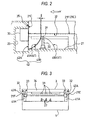
- the battery chamber 21 has ascent/descent portion and a push-up portion (as will be called together the “ascent/descent push-up portions 41"), which construct a portion of the collision avoiding mechanism 4 and is protruded generally in a sector shape.
- These ascent/descent push-up portions 41 are disposed on the side wall faces 21A and 21B near the corner portions to cross the partition face 21C, as shown in Fig. 2.
- the ascent/descent push-up portion 41 has a curved face 41A (as will be called the "concavely curved face”), which is so recessed (in a smoothly arcuate shape) on the face confronting the partition face 21C as to form the ascent/descent portion.
- This concavely curved face 41A descends (or ascends) the leading end portion of the battery pack 3, when this battery pack 3 is loaded (or unloaded), smoothly in a mounting ( ⁇ ) direction.
- the curvature (or the radius of curvature) is suitably determined according to the disposed position of the pin terminals 22, such as the distance from the partition face 21C or the height of the side wall faces 21A and 21B.
- a curved face 41B (as will be called the "convexly curved face"), which is curved in a convex sector shape (or in a smoothly arcuate shape) to form the push-up portion.
- the convexly curved face 41B pushes up the later-described leading end portion of the battery pack 3, when this battery pack 3 is loaded, smoothly in accordance with the height of the pin terminals 22.
- the shape and curvature of the curved face 41B are not univocally determined but are sufficient so long as the battery pack 3 can be smoothly pushed up.
- the battery pack 3 has a body portion formed into a thin box shape.
- Back electrodes 31 are disposed in the same number and arrangement on such one end portion (as will be called the "leading end portion") of the back of the battery pack 3 as corresponds to the disposed position of the pin terminals 22 of the battery chamber 21.
- this battery pack 3 has riding portions 42, which protrude generally in a sector shape to form a part of the collision avoiding mechanism 4. These riding portions 42 protrude from the two left and right sides of that leading end portion of the back of the battery pack 3, which confronts the ascent/descent push-up portions 41.
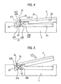
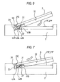
- the riding portions 42 smoothly ride on and over the ascent/descent push-up portions 41 while sliding on the sector-shaped concavely curved faces 41A of the ascent/descent push-up portions 41, thereby to avoid the battery pack 3 reliably from colliding against the pin terminals 22.
- the leading end faces 35 to confront the partition face 21C form flat faces 42A (as will be called the “depending faces”) extending vertically downward from the body portion of the battery pack 3.
- the faces of the side opposed to the depending faces 42A are concavely curved (in a smooth arcuate shape) to form curved faces 42B (as will be called the “convexly curved faces”).
- the convexly curved faces 42B are given such a curvature (or a radius of curvature) substantially equal to that of the concavely curved faces 41A that they may substantially fit on the concavely curved faces 41A of the ascent/descent push-up portions 41 when the battery pack 6 is mounted, while finally retaining the later-described cleaning area ⁇ (or the cleaning stroke) (as referred to Fig. 2).
- this cleaning area ⁇ (or the cleaning stroke) is provided for cleaning and removing the dust or another insulator, which may stick to the back electrodes 31 of the battery pack 3 or the pin terminals 22 of the battery chamber 21 simultaneously as the battery pack 3 is loaded or unloaded.
- the back electrodes 31 of the battery pack 3 are allowed by that area to contact with / slide to the pin terminals 22 of the battery chamber 21.
- this battery pack 3 has the received portions 32 of a step shape, which perpendicularly intersect across the spacing W with the widthwise direction in the whole lengthwise direction on the two transverse side faces. These received portions 32 construct one guide unit at the time when they are loaded while sliding on the slide faces 21E and 21F of the battery chamber 21.
- the portion of the casing 2 of the body 1 of the mobile telephone and the battery pack 3 are provided with a lock mechanism for preventing the battery pack 3 from floating or coming out after the battery pack 3 was loaded into the battery chamber 21.
- the casing 2 of the body 1 has the locking holes 23 in the partition face 21C confronting the battery chamber 21, as shown in Fig. 2, and the battery pack 3 has protruding locking pawls 33 to engage with the locking holes 23, thereby to construct the lock mechanism.
- the locking action by the locking mechanism is continuously performed while the battery pack 3 is being slid along the floor face of the battery chamber 21.
- the locking action after the riding action is performed while the back electrodes 31 of the battery pack 3 are contacting with / sliding on the pin terminals 22 in the battery chamber 21. In other words, the locking action is performed together with the cleaning action.
- the casing 2 on the side of the body 1 and the battery pack 3 are provided with the sector-shaped ascent/descent push-up portions 41 and the sector-shaped riding portions 42 as the collision avoiding mechanisms 4.
- the arcuately curved faces are made to engage with each other, and the loading/unloading operations are done while turning the battery pack 3.
- the battery pack 3 can be descended precisely in a pin point to the desired loading position.
- these highly precise loading/unloading actions can be realized to ensure the reliable conductions even if the battery chamber 21 is provided with not the conventional spring terminals but the pin terminals 22 as the connecting terminals.
- the connecting terminals can be small-sized and shortened. Especially in case the connecting terminals are made of gold (Au), the cost can be lowered.
- the pin terminals are provided as the connecting terminals, but the connecting terminals of the invention may be the spring terminals (as designated at 103 in Fig. 17) used in the prior art.
- the spring terminals are so shaped that the crests positioned at the central portions are folded and protruded generally in a v shape, and are given such spring properties that they can move vertically of the floor face of the battery chamber 21.
- the spring terminals absorb the fluctuations of their spacings from the back electrodes 31 of the battery pack 3 by moving them in the longitudinal (Y) direction (i.e., in the longer direction in the casing 2 of the body of the mobile telephone) with respect to the floor face.
- the back electrodes 31 of the battery pack 3 come into contact with the pin terminals 22 in the battery chamber 21 so that they become electrically conductive with the pin terminals 22 being pushed down.
- the sliding motions are kept with the back electrodes 31 of the battery pack 3 and the pin terminals 22 in the battery chamber 21 being in contact with each other. Therefore, the deposits such as dust or tailings having stuck to both of them to cause insufficient insulation can be cleaned/removed to ensure their electric contacts.
- the unloading operations to unload the battery pack 3 from the battery chamber 21 can be absolutely reversed from those of the aforementioned case of loading the battery pack 3.
- the battery pack 3 can be smoothly taken out without any rattling while being prevented from colliding against the pin terminals 22 or sliding.
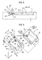
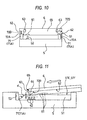
- Fig. 9 shows a mobile telephone according to a second embodiment of the invention.
- This mobile telephone used is of a folding type (or an opening/closing type), and is provided as its major components with the body 1 and a battery pack 6 to be removably mounted in the body 1.
- These body 1 and battery pack 6 are equipped with collision avoiding mechanisms 7.
- the body 1 has its casing portion composed of the not-shown upper casing and a lower casing 5, which are connected to each other at a hinge H.
- the lower casing 5 is formed generally into a thin box shape. Especially in this folding type mobile telephone, the lower casing 5 has a wide shape, in which its size in the widthwise (X) direction is larger than the size in the lengthwise (Y) direction perpendicular to the former.
- the not-shown various operation keys are attached to the surface 5A.
- the battery chamber 51 is formed in the lower side of the back of the lower casing 5, i.e., over an about one half or more of the entire back. Especially in this folding type mobile telephone, the battery chamber 51 is also formed into such a wide shape and a generally rectangular shape according to the wide shape of the lower casing 5 that the transverse (X) direction (or the widthwise or shorter direction) is larger than the longitudinal direction (or the longer direction).
- this battery chamber 51 is defined on its two left and right sides by lower and longer inner wall faces 51A and 51B (as will be called the “side wall faces”) and on its two upper and lower sides perpendicular to the left and right sides by a shorter high inner wall face 51C (as will be called the “partition face”) and a shorter low wall face 51D.
- partition face 51C there are formed the later-described locking holes 53 on the two left and right sides.
- the battery chamber 51 is provided at the individual side wall faces 51A and 51B with left and right slender frame faces 51E and 51F, which are disposed in parallel while holding the spacing W.
- the later-described received portions 62 of the battery pack 6 slide and move on the frame faces 51E and 51F.
- pin terminals 52 for electric contact to the battery pack 6 are disposed in the floor face side of the casing 5.
- a plurality of (e.g., ordinary three) pin terminals 52 are arranged in series.
- the widthwise (X) direction of the lower casing 5 is wider, as described hereinbefore.
- the battery chamber 51 has a relatively sufficient space in the widthwise direction.
- the pin terminals 52 are arranged in parallel with the lengthwise (Y) direction perpendicular to the widthwise direction.
- the not-shown major electronic parts of the mobile telephone are disposed in the lower casing 5 of the body 1 of the mobile telephone and exclusively on the upper side avoiding the lower side, in which the battery chamber 51 is located.
- the pin terminals 52 are disposed close to the upper portion of the battery chamber 51 close to the upper portion of the lower casing 5 so that the voltage drop or the like at the time of power feed from the power source can be minimized like the first embodiment.
- the battery chamber 51 has ascent/descent portion and a push-up portion (as will be called together the "ascent/descent portions 71"), which construct a portion of the collision avoiding mechanism 7 and is protruded generally in a sector shape.
- These ascent/descent portions 71 are disposed on the side wall faces 51A and 51B near the corner portions to cross the partition face 51C, as shown in Fig. 9.
- the ascent/descent portion 71 has a curved face 71A (as will be called the "concavely curved face”), which is so recessed in a concave sector shape (in a smoothly arcuate shape) on the face confronting the partition face 51C as to form the ascent/descent portion.
- This concavely curved face 71A descends the leading end portion, when this battery pack 6 is loaded, smoothly in a mounting ( ⁇ ) direction.
- the curvature (or the radius of curvature) is suitably determined according to the disposed position of the pin terminals 52, such as the distance from the partition face 51C or the height of the side wall faces 51A and 51B.
- a pair of left and right slender frame faces 51E and 51F (which form the push-up portions, as will be called the "push-up faces"), which are disposed in parallel while holding the spacing W.
- the later-described received portions 62 of the battery pack 6 slide and move on the frame faces 51E and 51F to ride over the pin terminals 52 thereby to avoid collision against the pin terminals 22.
- the battery pack 6 has a body portion formed into a thin box shape.
- Back electrodes 61 are disposed in the same number and in series on such one end portion close to the side faces of the back of the battery pack 3 as corresponds to the disposed positions of the pin terminals 52 of the battery chamber 51.
- this battery pack 6 has riding portions 72, which protrude generally in a sector shape to form a part of the collision avoiding mechanism 7. These riding portions 72 protrude from the two left and right sides of that leading end portion of the back of the battery pack 6, which confronts the ascent/descent portions 71. The riding portions 72 smoothly descends on the ascent/descent portions 71 while sliding on the sector-shaped concavely curved faces 71A of the ascent/descent portions 71, thereby to avoid the battery pack 3 reliably from colliding against the pin terminals 22.
- the riding portions 72 are provided with flat faces 72A (as will be called the "depending faces"), which extend vertically downward from the leading end face 65 (as referred to Fig. 10) of the body portion and which confront the partition face 51C. Moreover, the riding portions 72 are provided, on the side opposed to the depending faces 72A, with convexly curved faces 72B which are curved in a convex sector shape (or in a smoothly arcuate shape).
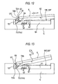
- These convexly curved faces 72B are given such a curvature (or a radius of curvature) substantially equal to that of the concavely curved faces 51A, that they may substantially fit on the concavely curved faces 51A of the push-up portions 51 while retaining the later-described cleaning area ⁇ (or the cleaning stroke) (as referred to Fig. 16), when the battery pack 6 is loaded to the last.
- this cleaning area ⁇ (or the cleaning stroke) is provided for cleaning and removing the dust or another insulator, which may stick to the back electrodes 31 of the battery pack 3 or the pin terminals 22 of the battery chamber 21 simultaneously as the battery pack 3 is loaded or unloaded.
- the back electrodes 31 of the battery pack 3 are allowed by that area to contact with / slide to the pin terminals 22 of the battery chamber 21.
- this battery pack 6 has the received portions 62 of a step shape, which perpendicularly intersect across the spacing W with the widthwise (X) direction in the whole lengthwise (Y) direction on the two transverse side faces.
- These received portions 62 construct guide means at the time when they are loaded while sliding on the slide faces 51E and 51F of the battery chamber 51.
- the lower casing 5 of the body 1 of the mobile telephone and the battery pack 6 are provided with a lock mechanism for preventing the battery pack 6 from floating or coming out after the battery pack 6 was loaded into the battery chamber 51.
- the lower casing 5 of the body 1 has the locking holes 53 in the partition face 51C confronting the battery chamber 51, as shown in Fig. 9, and the battery pack 6 has protruding locking pawls 63 to engage with the locking holes 53, thereby to construct the lock mechanism.
- the locking action by the locking mechanism is continuously performed while the battery pack 3 is being slid along the floor face of the battery chamber 21.
- the locking action after the riding action is performed while the back electrodes 61 of the battery pack 6 are contacting with / sliding on the pin terminals 52 in the battery chamber 51. In other words, the locking action is performed together with the cleaning action.
- the pin terminals 52 are provided in the battery chamber 51 as the connecting terminals, but may be the spring terminals (as designated at 103 in Fig. 17) used in the prior art.
- the back electrodes 61 of the battery pack 6 come into contact with the pin terminals 52 in the battery chamber 51 so that they become electrically conductive therewith.
- the sliding motions are kept with the back electrodes 61 of the battery pack 6 and the pin terminals 52 in the battery chamber 51 being in sliding contact. Therefore, the deposits such as dust or tailings having stuck to both of them to cause insufficient insulation can be cleaned/removed to ensure their electric contacts.
- the unloading operations to unload the battery pack 6 from the battery chamber 51 can be absolutely reversed from those of the aforementioned case of loading the battery pack 6.
- the battery pack 6 can be smoothly taken out without any rattling while being prevented from colliding against the pin terminals 52 or sliding.
- a mobile electronic apparatus including: its body having a battery chamber recessed generally in a rectangular shape in the lower portion of a back side of a casing, as opposed to a surface side having an operation unit and a display unit; and a battery pack adapted to be removably housed in the battery chamber formed in the casing back face of the body, characterized by comprising: collision avoiding mechanisms including: generally sector-shaped ascent/descent portions and suitably shaped push-up portions disposed higher than and corresponding to connecting terminals disposed in the battery chamber, on inner wall faces formed on the two sides along the loading direction of the battery pack so as to form the battery chamber and near the corner portions intersecting abutting wall faces perpendicular to the inner wall faces for forming the battery chamber; and riding portions formed on the back face of the battery pack confronting the ascent/descent portions and the push-up portions on the two widthwise sides of the battery pack and ascending/descending while sliding on the sector-shaped faces of the push-up portions thereby to ride over
- an area for a cleaning action to clean the outer faces of the connecting terminals or back electrodes disposed in the battery pack is retained between the ascent/descent portions of the casing on the body side of the mobile electronic apparatus and the riding portions of the battery pack at the time when the battery pack is loaded into the mobile electronic apparatus.
- the connecting terminals and the electrodes can be cleaned in association with the loading/unloading operation.
- the electric contact failure can be prevented even for a long-term use or under a dusty environment.
Landscapes
- Engineering & Computer Science (AREA)
- Signal Processing (AREA)
- Battery Mounting, Suspending (AREA)
- Telephone Set Structure (AREA)
- Charge And Discharge Circuits For Batteries Or The Like (AREA)
Applications Claiming Priority (1)
| Application Number | Priority Date | Filing Date | Title |
|---|---|---|---|
| PCT/JP2002/010616 WO2004034488A1 (ja) | 2002-10-11 | 2002-10-11 | 携帯電子機器 |
Publications (2)
| Publication Number | Publication Date |
|---|---|
| EP1551068A1 true EP1551068A1 (de) | 2005-07-06 |
| EP1551068A4 EP1551068A4 (de) | 2010-02-24 |
Family
ID=32089058
Family Applications (1)
| Application Number | Title | Priority Date | Filing Date |
|---|---|---|---|
| EP02807981A Withdrawn EP1551068A4 (de) | 2002-10-11 | 2002-10-11 | Tragbares elektronisches gerät |
Country Status (6)
| Country | Link |
|---|---|
| US (1) | US7242973B2 (de) |
| EP (1) | EP1551068A4 (de) |
| JP (1) | JP4294591B2 (de) |
| CN (1) | CN100385710C (de) |
| AU (1) | AU2002368277A1 (de) |
| WO (1) | WO2004034488A1 (de) |
Families Citing this family (23)
| Publication number | Priority date | Publication date | Assignee | Title |
|---|---|---|---|---|
| KR100827104B1 (ko) * | 2003-10-23 | 2008-05-02 | 삼성전자주식회사 | 휴대용 전자 장치 |
| JP4591003B2 (ja) * | 2004-09-17 | 2010-12-01 | 株式会社デンソーウェーブ | 電子装置 |
| JP4782403B2 (ja) * | 2004-10-25 | 2011-09-28 | 株式会社平和 | 遊技機 |
| JP2008252534A (ja) * | 2007-03-30 | 2008-10-16 | Fujitsu Ltd | 携帯端末装置、充電器および携帯端末装置が装着されるアダプタ |
| USD587695S1 (en) * | 2007-05-14 | 2009-03-03 | Motorola, Inc. | Communication device cradle |
| TW200903914A (en) * | 2007-07-13 | 2009-01-16 | Ks Terminals Inc | Battery terminal connector, portable communicating devices with the connector and battery connecting method thereof |
| TW200909700A (en) * | 2007-08-17 | 2009-03-01 | Asustek Comp Inc | Foldable electronic device |
| USD610135S1 (en) * | 2009-01-06 | 2010-02-16 | Research In Motion Limited | Hand-held electronic device back housing assembly |
| USD609226S1 (en) * | 2009-01-06 | 2010-02-02 | Research In Motion Limited | Hand-held electronic device back housing assembly |
| WO2014100965A1 (en) * | 2012-12-25 | 2014-07-03 | Nokia Corporation | A cover and apparatus for locking the cover |
| USD756187S1 (en) * | 2014-07-11 | 2016-05-17 | Pressmaster Ab | Adjustable crimping guide die |
| JP6152404B2 (ja) * | 2015-07-28 | 2017-06-21 | 京セラ株式会社 | 電子機器 |
| JP6080235B1 (ja) * | 2015-12-01 | 2017-02-15 | Necプラットフォームズ株式会社 | 電池パックの収容構造、および電子機器 |
| US9799947B1 (en) * | 2016-06-06 | 2017-10-24 | Motorola Mobility Llc | Modular device system desense reduction |
| US9634774B1 (en) * | 2016-06-06 | 2017-04-25 | Motorola Mobility Llc | Desense reduction via pin remap in modular device |
| US9837682B1 (en) * | 2016-08-29 | 2017-12-05 | Microsoft Technology Licensing, Llc | Variable layer thickness in curved battery cell |
| JP6116039B1 (ja) * | 2017-01-11 | 2017-04-19 | Necプラットフォームズ株式会社 | 電池パックの収容構造、および電子機器 |
| JP6191796B1 (ja) * | 2017-02-10 | 2017-09-06 | ソニー株式会社 | バッテリー及び接続機器 |
| US10734746B2 (en) * | 2017-07-28 | 2020-08-04 | Casio Computer Co., Ltd. | Terminal structure, portable terminal and manufacturing method of terminal section |
| JP6555305B2 (ja) * | 2017-08-08 | 2019-08-07 | ソニー株式会社 | バッテリー及び接続機器 |
| US11382221B2 (en) * | 2019-11-19 | 2022-07-05 | Ricoh Company, Ltd. | Information display device |
| EP4117101B1 (de) * | 2021-04-29 | 2024-06-12 | Solum Co., Ltd. | Batteriegehäuse und elektronischer preisanzeiger damit |
| JP2023030527A (ja) * | 2021-08-23 | 2023-03-08 | Dynabook株式会社 | 電子機器 |
Family Cites Families (19)
| Publication number | Priority date | Publication date | Assignee | Title |
|---|---|---|---|---|
| JPS647760U (de) * | 1987-07-03 | 1989-01-17 | ||
| JPH0767015B2 (ja) * | 1987-08-07 | 1995-07-19 | 松下電器産業株式会社 | 電気機器 |
| JPS6442199U (de) | 1987-09-09 | 1989-03-14 | ||
| US5189358A (en) * | 1991-05-07 | 1993-02-23 | Fujitsu Limited | Adaptor for mounting portable radio apparatus to moving body and charger for portable radio apparatus |
| EP0587761A4 (en) * | 1991-06-03 | 1994-08-17 | Motorola Inc | Portable radio battery latch |
| JPH0647760U (ja) * | 1992-12-07 | 1994-06-28 | 安生 樋口 | 減速装置 |
| US5308716A (en) | 1993-09-20 | 1994-05-03 | Motorola, Inc. | Battery pack retention apparatus |
| US5606594A (en) * | 1994-01-27 | 1997-02-25 | Dell Usa, L.P. | Communication accessory and method of telecommunicating for a PDA |
| JP3376569B2 (ja) | 1995-08-31 | 2003-02-10 | 株式会社ケンウッド | 電子機器のバッテリー着脱機構 |
| US5933330A (en) * | 1998-05-14 | 1999-08-03 | Motorola, Inc. | Portable radiotelephone arrangement having a battery pack and a detachable battery |
| JP2954166B1 (ja) | 1998-06-04 | 1999-09-27 | 埼玉日本電気株式会社 | 携帯無線機のバッテリ保持構造 |
| JP2000236378A (ja) * | 1999-02-16 | 2000-08-29 | Matsushita Electric Ind Co Ltd | 携帯電話装置 |
| JP3012642B1 (ja) | 1999-03-12 | 2000-02-28 | 埼玉日本電気株式会社 | バッテリ保持構造と該バッテリ保持構造を備えた携帯型電子機器 |
| KR100315673B1 (ko) * | 2000-01-11 | 2001-11-29 | 윤종용 | 휴대용 무선단말기의 배터리팩 로킹장치 |
| JP2001285431A (ja) * | 2000-04-03 | 2001-10-12 | Matsushita Electric Ind Co Ltd | 携帯機器における内蔵バッテリー保持構造 |
| JP2002124230A (ja) | 2000-10-13 | 2002-04-26 | Tookado:Kk | 電池のスイッチ |
| JP2002141994A (ja) * | 2000-11-02 | 2002-05-17 | Mitsubishi Electric Corp | 携帯機器 |
| JP4306143B2 (ja) * | 2001-04-27 | 2009-07-29 | 日本電気株式会社 | 携帯電話機 |
| JP3686845B2 (ja) * | 2001-05-21 | 2005-08-24 | 埼玉日本電気株式会社 | 折り畳み型携帯電話機 |
-
2002
- 2002-10-11 EP EP02807981A patent/EP1551068A4/de not_active Withdrawn
- 2002-10-11 AU AU2002368277A patent/AU2002368277A1/en not_active Abandoned
- 2002-10-11 CN CNB028297458A patent/CN100385710C/zh not_active Expired - Fee Related
- 2002-10-11 WO PCT/JP2002/010616 patent/WO2004034488A1/ja not_active Ceased
- 2002-10-11 JP JP2004542800A patent/JP4294591B2/ja not_active Expired - Fee Related
- 2002-10-11 US US10/530,925 patent/US7242973B2/en not_active Expired - Fee Related
Also Published As
| Publication number | Publication date |
|---|---|
| EP1551068A4 (de) | 2010-02-24 |
| CN1685538A (zh) | 2005-10-19 |
| US7242973B2 (en) | 2007-07-10 |
| US20060079298A1 (en) | 2006-04-13 |
| CN100385710C (zh) | 2008-04-30 |
| WO2004034488A1 (ja) | 2004-04-22 |
| JP4294591B2 (ja) | 2009-07-15 |
| JPWO2004034488A1 (ja) | 2006-02-09 |
| AU2002368277A1 (en) | 2004-05-04 |
Similar Documents
| Publication | Publication Date | Title |
|---|---|---|
| EP1551068A1 (de) | Tragbares elektronisches gerät | |
| US6729413B2 (en) | Power tool with battery pack ejector | |
| CN100479253C (zh) | 电池组 | |
| CN1213503C (zh) | 电池组充电装置 | |
| DE102015000142B4 (de) | Batteriepack mit Temperaturerfassungsvorrichtung | |
| CN1433112A (zh) | 卡连接器 | |
| US9054540B2 (en) | Electrical charging device and electrical docking station | |
| CN100568628C (zh) | 导电销 | |
| KR102025366B1 (ko) | 배터리 장착 장치 | |
| CN102223777A (zh) | 具有后盖弹开机构的电子装置 | |
| US20050084747A1 (en) | Latching mechanism for electronic device and method of assembly | |
| JP3935830B2 (ja) | カードコネクタ | |
| JP2003151525A (ja) | 電池のリード電極に対する接触子の接触方法および電池充放電装置ならびに電池充放電システムならびにそれらに用いられる接触子 | |
| CN218975654U (zh) | 一种电池仓及电池柜 | |
| CN214254502U (zh) | 一种定位装置 | |
| CN217333344U (zh) | Rfid手持机 | |
| GB2251134A (en) | Ejector-equipped card connector | |
| KR20050091699A (ko) | 이동 전자장치 | |
| JP3136568U (ja) | カード挿入保護型コネクタ | |
| JP2005018995A (ja) | 電気機器および電気機器用パック電池 | |
| CN104218345A (zh) | 电连接器组件 | |
| CN115800427A (zh) | 充电柜 | |
| CN201204320Y (zh) | 多合一记忆卡的连接器结构 | |
| CN1521897A (zh) | 用于便携式数字设备的卡插槽单元 | |
| JP2007115717A (ja) | バッテリーパック |
Legal Events
| Date | Code | Title | Description |
|---|---|---|---|
| PUAI | Public reference made under article 153(3) epc to a published international application that has entered the european phase |
Free format text: ORIGINAL CODE: 0009012 |
|
| 17P | Request for examination filed |
Effective date: 20050411 |
|
| AK | Designated contracting states |
Kind code of ref document: A1 Designated state(s): AT BE BG CH CY CZ DE DK EE ES FI FR GB GR IE IT LI LU MC NL PT SE SK TR |
|
| AX | Request for extension of the european patent |
Extension state: AL LT LV MK RO SI |
|
| DAX | Request for extension of the european patent (deleted) | ||
| RBV | Designated contracting states (corrected) |
Designated state(s): DE FR GB |
|
| RIN1 | Information on inventor provided before grant (corrected) |
Inventor name: JYUUDAI, KANTA Inventor name: TAKANASHI, TADAYUKI Inventor name: KOBAYASHI, TSUYOSHIC/O MATSUSHITA ELECTRIC IND. Inventor name: SAITOH, EIJI |
|
| RAP1 | Party data changed (applicant data changed or rights of an application transferred) |
Owner name: PANASONIC CORPORATION |
|
| A4 | Supplementary search report drawn up and despatched |
Effective date: 20100122 |
|
| 17Q | First examination report despatched |
Effective date: 20100730 |
|
| STAA | Information on the status of an ep patent application or granted ep patent |
Free format text: STATUS: THE APPLICATION IS DEEMED TO BE WITHDRAWN |
|
| 18D | Application deemed to be withdrawn |
Effective date: 20140501 |