EP1551604B1 - Schärfeinheit für scheibenförmige messer, schneidmaschine mit einer schärfeinheit und schärfverfahren - Google Patents
Schärfeinheit für scheibenförmige messer, schneidmaschine mit einer schärfeinheit und schärfverfahren Download PDFInfo
- Publication number
- EP1551604B1 EP1551604B1 EP03772664A EP03772664A EP1551604B1 EP 1551604 B1 EP1551604 B1 EP 1551604B1 EP 03772664 A EP03772664 A EP 03772664A EP 03772664 A EP03772664 A EP 03772664A EP 1551604 B1 EP1551604 B1 EP 1551604B1
- Authority
- EP
- European Patent Office
- Prior art keywords
- blade
- grinding wheel
- cutting edge
- inclination
- cutting
- Prior art date
- Legal status (The legal status is an assumption and is not a legal conclusion. Google has not performed a legal analysis and makes no representation as to the accuracy of the status listed.)
- Expired - Lifetime
Links
Images


Classifications
-
- B—PERFORMING OPERATIONS; TRANSPORTING
- B24—GRINDING; POLISHING
- B24B—MACHINES, DEVICES, OR PROCESSES FOR GRINDING OR POLISHING; DRESSING OR CONDITIONING OF ABRADING SURFACES; FEEDING OF GRINDING, POLISHING, OR LAPPING AGENTS
- B24B3/00—Sharpening cutting edges, e.g. of tools; Accessories therefor, e.g. for holding the tools
- B24B3/36—Sharpening cutting edges, e.g. of tools; Accessories therefor, e.g. for holding the tools of cutting blades
- B24B3/368—Sharpening cutting edges, e.g. of tools; Accessories therefor, e.g. for holding the tools of cutting blades installed as an accessory on another machine
-
- B—PERFORMING OPERATIONS; TRANSPORTING
- B24—GRINDING; POLISHING
- B24B—MACHINES, DEVICES, OR PROCESSES FOR GRINDING OR POLISHING; DRESSING OR CONDITIONING OF ABRADING SURFACES; FEEDING OF GRINDING, POLISHING, OR LAPPING AGENTS
- B24B3/00—Sharpening cutting edges, e.g. of tools; Accessories therefor, e.g. for holding the tools
- B24B3/36—Sharpening cutting edges, e.g. of tools; Accessories therefor, e.g. for holding the tools of cutting blades
- B24B3/46—Sharpening cutting edges, e.g. of tools; Accessories therefor, e.g. for holding the tools of cutting blades of disc blades
-
- B—PERFORMING OPERATIONS; TRANSPORTING
- B26—HAND CUTTING TOOLS; CUTTING; SEVERING
- B26D—CUTTING; DETAILS COMMON TO MACHINES FOR PERFORATING, PUNCHING, CUTTING-OUT, STAMPING-OUT OR SEVERING
- B26D1/00—Cutting through work characterised by the nature or movement of the cutting member or particular materials not otherwise provided for; Apparatus or machines therefor; Cutting members therefor
- B26D1/0006—Cutting members therefor
-
- B—PERFORMING OPERATIONS; TRANSPORTING
- B26—HAND CUTTING TOOLS; CUTTING; SEVERING
- B26D—CUTTING; DETAILS COMMON TO MACHINES FOR PERFORATING, PUNCHING, CUTTING-OUT, STAMPING-OUT OR SEVERING
- B26D3/00—Cutting work characterised by the nature of the cut made; Apparatus therefor
- B26D3/16—Cutting rods or tubes transversely
-
- B—PERFORMING OPERATIONS; TRANSPORTING
- B26—HAND CUTTING TOOLS; CUTTING; SEVERING
- B26D—CUTTING; DETAILS COMMON TO MACHINES FOR PERFORATING, PUNCHING, CUTTING-OUT, STAMPING-OUT OR SEVERING
- B26D7/00—Details of apparatus for cutting, cutting-out, stamping-out, punching, perforating, or severing by means other than cutting
- B26D7/08—Means for treating work or cutting member to facilitate cutting
- B26D7/12—Means for treating work or cutting member to facilitate cutting by sharpening the cutting member
-
- B—PERFORMING OPERATIONS; TRANSPORTING
- B26—HAND CUTTING TOOLS; CUTTING; SEVERING
- B26D—CUTTING; DETAILS COMMON TO MACHINES FOR PERFORATING, PUNCHING, CUTTING-OUT, STAMPING-OUT OR SEVERING
- B26D1/00—Cutting through work characterised by the nature or movement of the cutting member or particular materials not otherwise provided for; Apparatus or machines therefor; Cutting members therefor
- B26D1/0006—Cutting members therefor
- B26D2001/002—Materials or surface treatments therefor, e.g. composite materials
-
- B—PERFORMING OPERATIONS; TRANSPORTING
- B26—HAND CUTTING TOOLS; CUTTING; SEVERING
- B26D—CUTTING; DETAILS COMMON TO MACHINES FOR PERFORATING, PUNCHING, CUTTING-OUT, STAMPING-OUT OR SEVERING
- B26D1/00—Cutting through work characterised by the nature or movement of the cutting member or particular materials not otherwise provided for; Apparatus or machines therefor; Cutting members therefor
- B26D1/0006—Cutting members therefor
- B26D2001/0046—Cutting members therefor rotating continuously about an axis perpendicular to the edge
-
- B—PERFORMING OPERATIONS; TRANSPORTING
- B26—HAND CUTTING TOOLS; CUTTING; SEVERING
- B26D—CUTTING; DETAILS COMMON TO MACHINES FOR PERFORATING, PUNCHING, CUTTING-OUT, STAMPING-OUT OR SEVERING
- B26D1/00—Cutting through work characterised by the nature or movement of the cutting member or particular materials not otherwise provided for; Apparatus or machines therefor; Cutting members therefor
- B26D1/0006—Cutting members therefor
- B26D2001/0053—Cutting members therefor having a special cutting edge section or blade section
-
- B—PERFORMING OPERATIONS; TRANSPORTING
- B26—HAND CUTTING TOOLS; CUTTING; SEVERING
- B26D—CUTTING; DETAILS COMMON TO MACHINES FOR PERFORATING, PUNCHING, CUTTING-OUT, STAMPING-OUT OR SEVERING
- B26D2210/00—Machines or methods used for cutting special materials
- B26D2210/11—Machines or methods used for cutting special materials for cutting web rolls
Definitions
- the present invention relates to a method to sharpen disk-shaped cutting blades with a continuous cutting edge, and in particular to sharpen disk-shaped blades destined to cut rolls of web material such as paper, tissue paper, toilet tissue, kitchen towel and the like.
- the present invention also relates to a sharpening unit for disk-shaped blades, in particular for cutting machines destined to cut rolls of web material or the like, and cutting machines comprising said sharpening unit.
- Cutting machines are commonly used in the paper converting industry to produce small rolls from logs of wound paper, which have an axial length which is a multiple of the axial length of the finished products, corresponding to the axial dimension of the reels of paper coming from paper mills.
- the cutting machines commonly used to cut logs of paper or other wound web materials are provided with a unit rotating about an axis usually parallel to the direction of feed of the logs to be cut or slightly slanting in respect of it. These logs are fed along one or more channels parallel to one another to be subjected to the action of a rotating disk-shaped cutting blade carried by the rotating unit. The disk-shaped blade rotates about an axis in turn parallel to the direction of feed of the elongated products to be cut.
- machines of this type have intermittent or continuous feed (with variable or constant speed) of the logs. Examples of cutting machines of this type are described in US-RE-30598, EP-B-0507750, US-A-3213731, EP-B-0609668, US-A-5315907.
- the disk-shaped cutting blades used for this purpose are usually biconical in shape. That is, they are thicker in proximity to the axis and gradually decrease in thickness from the axis towards the edge.
- the cutting edge is formed of a bevel symmetrical in respect of the median plane orthogonal to the axis of the tool.
- the blade must be sharpened frequently to restore the cutting edge especially as it is produced with steels of limited hardness and toughness, such as high speed steels. Pairs of grinding wheels, motorized or more frequently drawn by the movement of the tool, are used for sharpening; these act in an approximately symmetrical manner on the two sides of the cutting bevel of the blade.
- the diameter of the blade is in this way gradually reduced from the original dimension to a minimum dimension of diameter, beyond which the blade must be replaced.
- the cutting edge becomes blunted and damaged rather quickly and must be sharpened frequently, which causes relatively rapid consumption of the blade, due to the wear caused by each sharpening operation. This makes it necessary to use high initial diameters, in order to reduce the number of replacements required and above all to amortize the cost of each blade against a sufficient quantity of cut product.
- the dimension of the product to be cut and of the hub to support the disk-shaped cutting blade make it impossible to go below a minimum dimension of diameter.
- the biconical shape of the tool produces a great deal of friction between the tool and the material to be cut. Moreover, to produce a biconically shaped tool, a large amount of initial raw material is required, as the biconical shape is obtained principally through grinding.
- blades have been designed with a cutting edge defined by two asymmetrical sides, one of which is hardened by facing the cutting profile with hard oxides.
- a blade of this type is described in WO-A-0021722.
- the purpose of this known blade is to increase the quantity of logs cut during the life of the blade, to reduce the number of sharpenings required during the useful life of the blade and to reduce the variation in blade diameter due to wear caused by sharpening.
- this blade did not attain the expected results in terms of duration, decrease in wear and reduction of sharpening frequency.
- the object of the present invention is to produce a sharpening unit that makes it possible to sharpen the blade efficiently decreasing wear and avoiding the need for substantial excursions of the sharpening grinding wheels to compensate for wear of the blade resulting from frequent sharpening operations.
- Yet another object of the present invention is to produce a method of sharpening that is simpler and more efficient sharpening than prior art methods, and a cutting machine that implements said method.
- the present invention relates to a sharpening unit to sharpen a disk-shaped blade, with a cutting bevel with a continuous circular cutting edge, and comprising a first grinding wheel and a second grinding wheel acting on a first side and on a second side of said bevel as defined in claim 1.
- the two grinding wheels are advantageously equipped with a movement to move them towards and away from the blade in a direction essentially parallel to their respective rotation axis.
- the object of this movement is to position the grinding wheels in the operating and non-operating position respectively and also to recover wear of the blade caused by the successive sharpening operations.
- the grinding wheel with larger grain is used to perform the actual sharpening and acts on the side of the bevel that, following initial sharpening, loses the surface hardening treatment.
- the first grinding wheel with extremely fine grain, acts on the side of the bevel destined to preserve the surface hardening treatment and acts simply to remove any burrs from the cutting edge, while also supporting the blade to prevent flexure caused by the pressure exerted by the second grinding wheel.
- the two grinding wheels may start to operate simultaneously. Nonetheless, to obtain optimal operation of the sharpening unit, the finest grinding wheel starts to operate before the grinding wheel with the larger grain and leaves the operating position with a delay.
- the delay with which the first grinding wheel disengages from the blade in respect of the moment at which the second grinding wheel ceases to act on the bevel of the blade is equal to at least one complete turn of the blade. This ensures that any burrs are eliminated from the cutting edge.
- the inclination of the first grinding wheel allows it to operate only in proximity to the cutting edge, that is at the tip of the bevel, and not along the entire extension of the side of the bevel.
- the thickness of surface treatment on the blade mean that the cutting edge, that is the line of intersection of the two sides and the surface area of the blade immediately adjacent to this line remain within the thickness of the material of the blade that has been subjected to the surface hardening treatment,. Independently of whether it is formed by a deposit or by the penetration of particles ⁇ e.g. by thermal treatment ⁇ in the structure of the base material forming the blade.
- the grinding wheels may be idle and hence drawn in rotation by the rotating blade. Nonetheless, they are preferably motorized.
- the motorized grinding wheels may be pressed against the blade with less pressure, thus making it possible to obtain a smoother ground surface.
- Mixed solutions may also be used in which one grinding wheel is drawn and the other motorized or in which there are more than two grinding wheels, some motorized and others drawn.
- the inclinations of the two grinding wheels are equal and opposite in respect of the lying plane of the cutting edge of the blade.
- the present invention relates to a cutting machine to cut logs of wound web material as defined in claim 9.
- the inclination of the first grinding wheel in respect of the first side of the bevel and the thickness of the hardening treatment may allow the cutting edge of the blade to remain within the volume that has been subjected to the hardening treatment.
- Yet another aspect of the present invention relates to a method to sharpen a disk-shaped blade rotating about an axis of rotation as defined in claim 24.
- FIG 1 schematically shows (limited to its front part) a cutting machine, as a whole indicated with 1, to which the present invention is applied.
- the machine has a feed path of the logs to be cut, indicated with L, which are pushed by pushers 3 secured to a flexible chain element or the like 5, driven about a driving wheel supported by a fixed structure 7. Only one driving wheel, indicated with 9, is visible in Figure 1, while the other is at the rear end of the cutting machine, not shown.
- the flexible elements 5 associated with the various parallel feed channels of the logs may be motorized separately from one another to stagger the movement of logs in each feed channel.
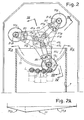
- the number 11 generically indicates a cutting head that, by means of a support 13, carries a rotating unit 17.
- the unit 17 rotates about a horizontal axis A-A parallel to the direction fL of feed of the logs L.
- three disk-shaped blades 19A, 19B and 19C are mounted on the rotating unit 17, disposed at 120° from one another about the axis A-A, as can be seen in particular in Figure 2.
- Each of the rotating disk-shaped blades 19A, 19B and 19C rotates about its own axis of rotation B-B parallel to the axis A-A and to the direction of feed fL of the logs L.
- the number 21 indicates a motor that, by means of a belt 23, transmits rotatory motion to the rotating unit 17.
- a second motor 25 is positioned on the support 13 of the rotating unit 17 and, by means of a belt 27, supplies rotatory motion to a shaft that drives disk-shaped blades 19A, 19B and 19C in rotation by means of a transmission to be described hereunder.
- a third motor 29 drives the driving wheel 9 of the rotating element 5 in rotation.
- a driving wheel 9 may be associated with each channel, with its own motor unit 29 suitably controlled as a function of the angular position of the rotating unit 17.
- the number 35 indicates a programmable control unit that synchronizes the angular position of the unit 17 with the feed movement of the flexible element(s) 5 acting on the motor(s) 29.
- Figures 2 and 3 show how the rotating unit 17, drawn in rotation by the hub 17A, internally supports three toothed wheels, positioned at 120° from one another about the axis A-A, indicated with 41A, 41B and 41C. Said wheels mesh with a central toothed wheel 43 keyed onto a shaft 45 that receives its motion from the motor 25 through the belt 27.
- the toothed wheels 41A, 41B and 41C are keyed onto respective spindles 47A, 47B and 47C onto which toothed pulleys 49A, 49B and 49C are in turn keyed.
- Each of the toothed pulleys 49A, 49B, 49C transmits the motion supplied by the motor 25, through toothed belts 51A, 51B, 51C, to the rotating disk-shaped cutting blades 19A, 19B e 19C.
- the toothed belt 51A, 51B, 51C transmits motion to a toothed pulley 53A, 53B, 53C keyed onto an axle 55A, 55B, 55C, on the opposite end of which the respective disk-shaped blade 19A, 19B, 19C is keyed.
- Each of the shafts is supported by bearings 57 in a respective sleeve 59A, 59B, 59C sliding on sliding bearings 61 mounted in a respective seat 63A, 63B, 63C provided in the rotating unit 17.
- the angular movement about the axis B-B of each sleeve 59A, 59B, 59C is prevented by a tab 58 integral with the respective sleeve, cooperating with wheels 60 supported idle in the sliding seat of the sleeve.
- each sleeve 59A, 59B, 59C has an enlarged area 65A, 65B, 65C that houses the toothed pulley 53A, 53B, 53C respectively, and mounted idle on which is a wheel 67A, 67B, 67C that constitutes the feeler for a fixed cam 71 extending in an arc of circumference, shown in particular in Figure 2 and in its development in the plane in Figure 2A.
- the arc of circumference along which the cam 71 extends has its center on the axis A-A of rotation of the rotating unit 17 and extends in the lower part of the path of each disk-shaped blade 19A, 19B, 19C, i.e. in the zone in which the blade is inserted into the product to be cut.
- each sleeve 59A, 59B, 59C associated with the respective disk-shaped blade 19A, 19B, 19C travels with alternate motion according to the double arrow fl. Consequently, the respective disk-shaped blade 19A, 19B, 19C are provided with the same motion.
- the movement according to the arrow fl is parallel to the direction of feed of the logs L or other elongated products to be cut.
- each disk-shaped blade 19A, 19B, 19C the blade is pushed forwards by the annular cam 71 that overcomes the compression strength of the respective Belleville springs 72A, 72B, 72C. In this way the blade that is operating at that time, i.e. inserted in the material constituting the log(s) L to be cut, moves forward following the forward motion of the logs L along the feed path.
- the forward movement is controlled by the ascending ramp 71A of the cam 71 (see Figure 2A).
- the forward motion starts before the respective blade 19A, 19B, 19C penetrates the material constituting the first of the logs to be cut, so that at the time in which contact with the blade starts it is already moving forward at the same speed as the material to be cut according to the arrow fL.
- the considerable length of the belts 51A, 51B and 51C provides the toothed pulley 53A, 53B or 53C with sufficient freedom of movement in the axial direction, so that the respective disk-shaped blades may advance and reverse without being obstructed by mechanical transmission of motion from the central axis.
- the axial'extension of the toothed pulleys 53A, 53B, 53C and 49A, 49B, 49C may be greater than the height of the respective belts 51A, 51B, 51C to allow any minor sliding of the belts on the driving pulleys.
- each sleeve 59A, 59B, 59C Integral with each sleeve 59A, 59B, 59C is a support 73A, 73B, 73C, each carrying a sharpening unit 80 comprising a pair of grinding wheels 81, 83 to sharpen the respective rotating disk-shaped blades 19A, 19B, 19C.
- a sharpening unit 80 comprising a pair of grinding wheels 81, 83 to sharpen the respective rotating disk-shaped blades 19A, 19B, 19C.
- Each grinding wheel of the pair of grinding wheels 81, 83 associated with each blade acts on one of the two sides of the cutting bevel of the blade, which will be described in detail with reference to Figures 5 to 7.
- the grinding wheels 81 and 83 may be motorized grinding wheels, that is drawn in rotation by specific motors such as pneumatic motors, although it is also possible to use grinding wheels mounted idle and drawn in rotation through the effect of contact friction with the disk-shaped blade. Feed of compressed air to the actuators associated with the three pairs of grinding wheels 81, 83 may be supplied by an axial rotating distributor, not shown and of a per se known type.
- the two grinding wheels 81, 83 of each sharpening unit 80 are also provided with a movement parallel to their axis of rotation to be brought alternately into contact with and moved away from the respective rotating disk-shaped blade, as sharpening is not continuous but performed only at regular intervals as the blade becomes blunt and thus requires sharpened.
- the structure of the mechanisms that make the grinding wheels rotate and cause them to move towards and away from the respective blade will be described with reference to Figures 9 and 10.
- the arrangement of the two grinding wheels 81, 83 of each sharpening unit 80 is shown in particular in the enlarged detail in Figure 8.
- Each of the blades 19A, 19B, 19C is designed as shown in Figures 5 to 7, which show any one of the three blades 19A, 19B, 19C, indicated simply with the reference 19.
- the blade 19 has a disk-shaped body delimited by two flat faces 201A, 201B parallel to each other, and a circular cutting edge 203. Therefore, essentially it has a continuous thickness in the range of 1.5-4 mm and preferably between 2 and 3 mm, in particular for example 2.5 mm.
- the cutting edge 203 represents the final edge of a cutting bevel, indicated as a whole with 205.
- This cutting bevel is delimited by two sides 207 and 209.
- the first side 207 extends radially (i.e. in the direction of the radius of the disk-shaped blade) to a greater extent than the radial extension of the second side 209.
- At least the side 207 has been subjected to surface hardening treatment.
- said treatment is a controlled nitriding thermal treatment, such as in particular Nitreg® treatment.
- the entire surface of the blade may be subjected to this treatment, as it is simpler and less expensive to perform complete treatment than to mask the parts of the blade that do not require to be treated.
- the entire surface of the blade may be subjected to treatment, with the exception of the side of the cutting bevel on which the grinding wheel with the largest grain, destined to perform actual sharpening, acts. In this way the duration of the grinding wheel may be extended.
- the controlled thermochemical nitriding treatment penetrates the base material of the blade for a depth T ( Figure 7), for example of around 100 micrometers.
- the surface hardening treatment can be provided in the form of a deposit of a harder material on the surface of the blade, or even in a depressed area of the blade body provided for the purpose of being filled up with said deposit.
- Figure 6A shows the bevel of the blade before the first sharpening operation with continuous surface treatment along its entire surface.
- the cutting edge 203 lies on a lying plane PG parallel to the median plane PM of the blade, which is represented by the plane orthogonal to the axis B-B of rotation and equidistant from the faces 201A, 201B of the body of the blade.
- the lying plane PG of the cutting edge 203 is shifted, in respect of the median plane PM of the blade, towards the second side 209 of the bevel 205.
- the side 207 is defined by a conical surface with axis coinciding with the axis B-B of rotation of the blade and with an inclination ⁇ in respect of the lying plane PG of the cutting edge 203.
- the angle ⁇ may for example be around 8°.
- the side 209 also has a conical form coaxial to the axis B-B and an inclination ⁇ in respect of the plane PG.
- the angle ⁇ is slightly greater than the angle ⁇ and may be for example equal to 10°. The possibility is not excluded, however, that the angle ⁇ is 0°.
- FIG 6B the blade is shown in its condition of maximum wear.
- the sides 207, 209 still have the same inclination, although the side 207 now extends in a radial direction for less than the side 209.
- the lying plane PG of the cutting edge 203 is moved in respect of the median plane PM towards the first side 207 and not towards the second side 209.
- the blade is produced in molybdenum chrome steel, such as X150CrMo12 steel, which with Nitreg® treatment even reaches a hardness equal to 72-73 HRC for the penetration depth of the controlled nitriding treatment.
- the two grinding wheels 81 and 83 are disposed with equal inclination and contrary in respect of the lying plane PG of the cutting edge 203 of the blade 19, that is in respect of a plane orthogonal to the axis B-B of rotation of the blade 19. More specifically, the two grinding wheels are inclined by an angle ⁇ in respect of the lying plane of the cutting edge of the blade.
- the grinding wheel 83 which acts on the side 209 inclined by an angle ⁇ in respect of the plane PG, operates parallel to the side and performs the actual sharpening of the blade. Removal of material from the side of the blade by the second grinding wheel 83 does not alter the conical shape of the side 209 of the bevel and its inclination in respect of the original inclination.
- the first grinding wheel 81 which acts on the side 207 of the bevel 205, only touches the side in the area nearest the cutting edge, due to the difference in inclination between the side 207 (inclined by an angle ⁇ in respect of the plane PG) and the grinding wheel (inclined by an angle ⁇ in respect of this plane).
- the contact conditions between the sides of the bevel 205 and the two grinding wheels are shown in the enlargement in Figure 7, where the two grinding wheels 81, 83 are indicated with a dashed line.
- the cutting edge 203 is produced wholly in a thickness of the material of the blade 19 subjected to this treatment.
- the cutting edge 203 and the portions of the sides of the bevel immediately adjacent to this cutting edge always remain within the thickness that has been subjected to hardening notwithstanding the amount of wear on the blade. Therefore, the cutting edge is hardened on both sides.
- thanks to the symmetrical layout of the grinding wheels 81, 83 it has a symmetrical section in respect of its lying plane PG, with consequent advantages in terms of dynamic stresses on the blade.
- the two grinding wheels 81 and 83 have markedly distinct abrasive characteristics.
- the second grinding wheel 83 is utilized for the actual sharpening operation and consequently has a grain size suitable for this purpose.
- the function of the grinding wheel 81 is to support the blade against the stresses exerted by the grinding wheel 83 and to eliminate any burrs produced along the cutting edge 203 by said grinding wheel 83, although it does not actually perform any sharpening operations, but merely polishes the bevel.
- the grinding wheel 81 may have diamond grains or equivalent and have an ⁇ extremely fine>> grain, that is from 7 to 46 (ISO standards), and preferably in proximity or equal to the minimum value 7, corresponding to a dimension of the sieve from 37 to 44 micrometers.
- the grinding wheel 83 may, on the contrary, be produced with the same type of abrasive and «fine» grain according to DIN and ISO 6106-1979 classification, that is between 45 and 91 (ISO standards), corresponding to screen meshes with dimensions between 53 and 74 micrometers.
- the grain size of this grinding wheel is around 70-80 (ISO).
- this also has the advantage of eliminating the need to provide the grinding wheels with a movement to move them gradually towards the axis of the blades in order to recover wear, and to adjust the position of the blade in respect of the axis of rotation of the unit carrying it, as the variation in diameter resulting from wear can be recovered by the simple movement towards the blade and away there from, with which the grinding wheels are periodically brought in the operating and non-operating position respectively.
- Figure 9 shows a longitudinal section of one of the grinding wheels 81 and of the relative axial supporting and traversing and rotation system.
- the grinding wheel 83 is mounted and rotation and traverse movement are controlled in the same manner.
- the grinding wheel 81 is keyed onto a shaft 85 supported by bearings 87 in a bushing 89.
- the bushing slides on the sliding bearings 91 inside a supporting sleeve 93 connected integral with the support 73C.
- the shaft 85 is connected to a hollow shaft 95 coupled by a spline coupling 97 to the motor shaft 99 of a pneumatic or equivalent motor 101.
- the bushing 89 has a helical groove 103 that extends through an arc of helix extremely reduced and inclined greatly in respect of the axis C-C of the shaft 85 of the grinding wheel 81.
- a wheel 105 mounted idle on a spindle 106 supported by the support 93 engages in the helical groove 103.
- the arrangement of the groove 103 and of the wheel 105 may be inverted, with the groove integral with the supporting sleeve 93 and the wheel integral with the bushing 89.
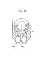
- Angular movement about the axis C-C of the bushing 89 is imparted by a pair of piston-cylinder actuators 108A, 108B parallel to each other, visible in particular in the section in Figure 10.
- the cylinders of these actuators are integral with the supporting sleeve 93, while the rods extend inside the sleeve and their ends rest on a leveled surface 110 produced on the bushing 89.
Landscapes
- Engineering & Computer Science (AREA)
- Mechanical Engineering (AREA)
- Life Sciences & Earth Sciences (AREA)
- Forests & Forestry (AREA)
- Finish Polishing, Edge Sharpening, And Grinding By Specific Grinding Devices (AREA)
- Polishing Bodies And Polishing Tools (AREA)
Claims (34)
- Schärfeinheit zum Schärfen eines scheibenförmigen Schneidmessers (19), welches eine Abschrägung (205) und eine zusammenhängende, kreisförmige Schneidkante (203) aufweist, mit einem ersten Schleifrad (81) und einem zweiten Schleifrad (83), welche auf eine erste Seite (207) und auf eine zweite Seite (209) der Abschrägung (205) einwirken, dadurch gekennzeichnet, dass das erste Schleifrad (81) ein feineres Korn hat als das zweite Schleifrad (83); dass die Neigung des ersten Schleifrades derart ist, dass dann, wenn die Einheit im Betrieb ist, das erste Schleifrad gegen die erste Seite (207) des Messers mit einer geringfügig größeren Neigung als die Neigung der ersten Seite bezüglich einer Kantenebene (PG) der Schneidkante des Messers zugestellt ist, während die Neigung des zweiten Schleifrades (83) im Wesentlichen parallel sich zu der zweiten Seite (209) der Abschrägung befindet und das zweite Schleifrad derart angeordnet und ausgeführt ist, dass es die Schneidschräge des Messers schärft, während das erste Schleifrad derart angeordnet und ausgeführt ist, dass es eine Gegenkraft auf das Messer ausübt, um eine Biegung des Messers im Schärfbereich zu verhindern oder zu reduzieren und jeden Grad, der von dem zweiten Schneidrad von der Schrieidkante erzeugt wird, zu eliminieren.
- Schärfeinheit nach Anspruch 1, dadurch gekennzeichnet, dass das erste und das zweite Schleifrad mit einer Bewegungsmöglichkeit zur Bewegung auf das Messer zu und von ihm weg versehen sind, und zwar entsprechend einer Richtung, die im Wesentlichen parallel zu ihren Rotationsachsen weist.
- Schärfeinheit nach Anspruch 2, dadurch gekennzeichnet, dass die Bewegungsmöglichkeit zum Bewegen des ersten und zweiten Schleifrades zum Messer hin derart gesteuert ist, dass das erste Schleifrad mit der ersten Seite des Messers in Kontakt kommt, ehe das zweite Schleifrad mit der zweiten Seite des Messers in Kontakt kommt, und sich aus dem Kontakt der ersten Seite des Messers entfernt, nachdem das zweite Schleifmesser sich aus dem Kontakt mit der zweiten Seite des Messers entfernt hat.
- Schärfeinheit nach Anspruch 3, dadurch gekennzeichnet, dass die Bewegungsmöglichkeit zur Bewegung der Schleifräder auf das Messer zu und von ihm weg derart gesteuert ist, dass das erste Schleifrad sich aus dem Kontakt mit der ersten Seite des Messers weg bewegt, nachdem das Messer wenigstens eine Umdrehung um seine Achse nach dem Wegbewegen des zweiten Schleifrades von der zweiten Seite ausgeführt hat.
- Schärfeinheit nach einem der Ansprüche 1 bis 4, dadurch gekennzeichnet, dass das erste und das zweite Schleifrad motorgetrieben sind.
- Schärfeinheit nach einem der Ansprüche 1 bis 5, dadurch gekennzeichnet, dass die Neigungen des ersten oder des zweiten Schleifrades entgegengesetzt gleich bezüglich einer Kantenebene der Schneidkante des Messers sind, wobei die Kanteebene im Wesentlichen orthogonal zur Drehachse des Messers ist.
- Schärfeinheit nach einem der Ansprüche 1 bis 6, dadurch gekennzeichnet, dass das erste Schleifrad eine extrem feine Körnung von 7 bis 46 der ISO-Norm, vorzugsweise etwa 7, besitzt.
- Schärfeinheit nach einem der Ansprüche 1 bis 7, dadurch gekennzeichnet, dass das zweite Schärfrad eine feine Körnung zwischen 45 und 91 gemäß ISO-Norm, vorzugsweise zwischen 70 und 80, besitzt.
- Schneidmaschine zum Schneiden von Rollen aufgewickelten Bahnmaterials mit wenigstens einem scheibenförmigen Messer (19), das um eine Drehachse (B-B) rotiert und eine Schneidabschrägung (205) und eine zusammenhängende Schneidkante (203) besitzt, die durch eine erste Seite (207) und durch eine zweite Seite (209) definiert ist, wobei die erste Seite eine größere radiale Ausdehnung hat als die zweite Seite, und wenigstens die erste Seite eine Oberflächenhärtbehandlung besitzt; mit wenigstens einer Schärfeinheit (80) für das Messer mit wenigstens einem ersten Schleifrad (81), welches auf die erste Seite (207) einwirkt, und einem zweiten Schleifrad (83), das auf die zweite Seite (209) einwirkt, dadurch gekennzeichnet, dass die Schärfeinheit nach einem oder mehreren der Ansprüche 1 bis 8 hergestellt ist.
- Schneidmaschine nach Anspruch 9, dadurch gekennzeichnet, dass die Neigung des ersten Schleifrades (81) bezüglich der ersten Seite (207) der Abschrägung und die Dicke (T) der Härtebehandlung es der Schneidkante (203) des Messers erlauben, innerhalb der Dicke zu bleiben, die der Härtebehandlung unterworfen worden ist.
- Schneidmaschine nach Anspruch 9 oder 10, dadurch gekennzeichnet, dass das erste und das zweite Schleifrad mit einer Bewegungsmöglichkeit ausgerüstet ist, um sie auf das Messer zu und von dem Messer weg entsprechend einer Richtung zu bewegen, die sich im Wesentlichen parallel zu ihren jeweiligen Rotationsachsen erstreckt, wobei die Bewegung auch die Abnutzung auf dem Messer durch aufeinander folgende Schärfvorgänge beseitigt.
- Schneidmaschine nach einem der Ansprüche 9 bis 11, dadurch gekennzeichnet, dass die Neigungen des ersten und des zweiten Schleifrades entgegengesetzt parallel bezüglich einer Kantenebene (PG) der Schneidkante (203) des Messers (19) sind, wobei die Ebene im Wesentlichen orthogonal zur Drehachse (B-B) des Messers sich erstreckt, und dass die Neigungen der beiden Seiten (207, 209) der Abschrägung (205) des Messers bezüglich der Kantenebene (PG) der Schneidkante des Messers unterschiedlich sind, wobei die erste Seite (207) bezüglich der Kantenebene eine kleinere Neigung als die zweite Seite (209) hat
- Schneidmaschine nach einem der Ansprüche 9 bis 12, dadurch gekennzeichnet, dass die erste Seite (207) sich im Wesentlichen parallel zur Kantenebene (PG) der Schneidkante des Messers erstreckt.
- Schneidmaschine nach Anspruch 12, dadurch gekennzeichnet, dass der Neigungsunterschied zwischen der ersten und der zweiten Seite wenigstens 1 Grad beträgt und vorzugsweise zwischen etwa 1,5 Grad und etwa 2,5 Grad beträgt.
- Schneidmaschine nach einem der Ansprüche 10 bis 14, dadurch gekennzeichnet, dass die Dicke der Härtebehandlung der ersten Seite gleich oder größer als 30 Mikrometer und vorzugsweise gleich oder größer als 80 Mikrometer ist, und zwar weiter bevorzugt gleich oder größer als 90 Mikrometer und noch weiter bevorzugt gleich oder größer als 100 Mikrometer ist.
- Schneidmaschine nach einem der Ansprüche 9 bis 15, dadurch gekennzeichnet, dass wenigstens die erste Seite des Messers eine Oberflächenhärte hat, die größer als 70 HRC und vorzugsweise gleich oder größer als etwa 72 HRC ist.
- Schneidmaschine nach einem der Ansprüche 9 bis 15, dadurch gekennzeichnet, dass das Messer aus Legierungsstahl besteht.
- Schneidmaschine nach einem der Ansprüche 9 bis 17, dadurch gekennzeichnet, dass wenigstens die erste Seite eine Oberflächenbehandlung aufweist, die durch Penetration von Molekülen oder Atomen in die Struktur des Basismaterials zur Bildung des Messers erhalten worden ist.
- Schneidmaschine nach Anspruch 18, in welcher die Oberflächenbehandlung eine gesteuerte Nitrit-Behandlung ist.
- Schneidmaschine nach einem der Ansprüche 9 bis 17, dadurch gekennzeichnet, dass wenigstens die erste Seite eine Oberflächenbehandlung erhalten hat, die aus einer Ablagerung eines Materials besteht, das härter ist als das Basismaterial, das das Messer bildet.
- Schneidmaschine wenigstens nach Anspruch 17, dadurch gekennzeichnet, dass das Messer aus Chromstahl mit einem Gehalt an Molybdän besteht.
- Schneidmaschine nach einem der Ansprüche 9 bis 21, dadurch gekennzeichnet, dass die Neigung der ersten Seite gleich oder kleiner als 9 Grad, vorzugsweise etwa gleich 8 Grad, bezüglich der Kantenebene (PG) ist.
- Schneidmaschine nach einem der Ansprüche 9 bis 22, dadurch gekennzeichnet, dass das Messer (19) einen von zwei Ebenen (201A, 201 B) begrenzten Korpus hat, die im Wesentlichen parallel zueinander und im Wesentlichen sich orthogonal zur Rotationsachse (B-B) des Messers erstrecken.
- Verfahren zum Schärfen eines scheibenförmigen Messers (19), um Rollen aus Bahnmaterial zu schneiden, welches um eine Rotationsachse (B-B) dreht und eine Schneidabschrägung (205) aufweist sowie eine zusammenhängende Schneidkante (203) besitzt, die von einer ersten Seite (207) und einer zweiten Seite (209) definiert ist, wobei die erste Seite in radiale Richtung eine größere Ausdehnung hat als die zweite Seite und wobei wenigstens die erste Seite eine Oberflächenhärtbehandlung erfahren hat, und wobei ein erstes Schleifrad (82) auf die erste Seite und ein zweites Schleifrad (83) auf die zweite Seite einwirken, dadurch gekennzeichnet, dass das erste Schleifrad (81) eine feinere Körnung hat als das zweite Schleifrad (83); dass das erste Schleifrad (81) gegen die erste Seite (207) des Messers mit einer geringfügig größeren Neigung als die Neigung der ersten Seite bezüglich einer Kantenebene (PG) der Schneidkante des Messers zugestellt ist, dass das zweite Schleifrad (83) gegen die zweite Seite des Messers mit einer Neigung zugestellt ist, die im Wesentlichen der Neigung der zweiten Seite bezüglich der Kantenebene entspricht; und dass das zweite Schleifrad die Schleifabschrägung schärft, während das erste Schleifrad eine Reaktionskraft auf das Messer ausübt, um ein Biegen des Messers im Schärfbereich zu verhindern oder zu reduzieren und um Grate zu eliminieren, die durch das zweite Schleifrad von der Schneidkante erzeugt werden.
- Verfahren nach Anspruch 24, dadurch gekennzeichnet, dass ein Messer benutzt wird, dessen Oberflächenhärtebehandlung eine Dicke von wenigstens 30 Mikrometern und vorzugsweise gleich oder größer als 80 Mikrometer und weiter bevorzugt gleich oder größer als 90 Mikrometer und noch weiter bevorzugt gleich oder größer als 100 Mikrometer aufweist.
- Verfahren nach Anspruch 24 oder 25, dadurch gekennzeichnet, dass die Neigung des ersten Schleifrades (81) bezüglich der ersten Seite (207) der Abschrägung und die Stärke der Härtebehandlung so gewählt sind, dass die Schneidkante (203) des Messers (19) innerhalb des Dickenbereiches durch die Härtebehandlung verbleibt.
- Verfahren nach einem der Ansprüche 24 bis 26, dadurch gekennzeichnet, dass das erste und das zweite Schleifrad motorisiert sind.
- Verfahren nach einem der Ansprüche 24 bis 27, dadurch gekennzeichnet, dass das erste Schleifrad und das zweite Schleifrad gegen das Messer mit einer Bewegung bewegt werden, die im Wesentlichen parallel zu den jeweiligen Rotationsachsen sich erstreckt, wobei die Bewegung auch die Abnutzung des Messers beseitigt, die durch aufeinanderfolgende Schärfungen erzeugt worden ist.
- Verfahren nach Anspruch 28, dadurch gekennzeichnet, dass das erste Schleifrad mit der ersten Seite des Messers in Kontakt kommt, ehe das zweite Schleifrad mit der zweiten Seite (209) des Messers in Kontakt kommt, und dass das erste Schleifrad sich aus dem Kontakt mit der ersten Seite des Messers heraus bewegt, nachdem das zweite Schleifrad sich aus dem Kontakt mit der zweiten Seite des Messers weg bewegt hat.
- Verfahren nach Anspruch 29, dadurch gekennzeichnet, dass die Bewegungsmöglichkeit, die Schleifräder auf das Messer zu und von ihm weg zu bewegen derart gesteuert ist, dass das erste Schleifrad sich aus dem Kontakt mit der ersten Seite des Messers heraus bewegt, nachdem das Messer wenigstens eine Umdrehung um seine Achse nach der Wegbewegung des zweiten Schleifrades von der zweiten Seite ausgeführt hat.
- Verfahren nach einem der Ansprüche 24 bis 30, dadurch gekennzeichnet, dass die Neigungen des ersten und des zweiten Schleifrades (83) entgegengesetzt gleich bezüglich einer Kantenebene der Schneidkante (203) des Messers (19) und im Wesentlichen orthogonal zur Rotationsachse (B-B) des Messers sind und dass die Neigungen der beiden Seiten (207, 209) der Abschrägung (205) des Messers bezüglich der Kantenebene (PG) der Schneidkante des Messers unterschiedlich sind, wobei die erste Seite bezüglich der Kantenebene weniger geneigt ist als die zweite Seite und dass die Schleifräder eine symmetrische Schleifkante bezüglich der Kantenebene der Schneidkante erfolgen.
- Verfahren nach Anspruch 31, dadurch gekennzeichnet, dass der Neigungsunterschied zwischen der ersten und der zweiten Seite wenigstens 1 Grad und vorzugsweise zwischen etwa 1,5 und etwa 2,5 Grad beträgt.
- Verfahren nach einem der Ansprüche 24 bis 32, dadurch gekennzeichnet, dass ein erstes Schleifrad mit einer extrem feinen Körnung von 7 bis 46 ISO-Norm, vorzugsweise etwa 7, benutzt wird.
- Verfahren nach einem der Ansprüche 24 bis 33, dadurch gekennzeichnet, dass ein zweites Schleifrad mit einer feinen Körnung von 45 bis 91 gemäß ISO-Norm und vorzugsweise von 70 bis 80 benutzt wird.
Applications Claiming Priority (3)
| Application Number | Priority Date | Filing Date | Title |
|---|---|---|---|
| IT000197A ITFI20020197A1 (it) | 2002-10-18 | 2002-10-18 | Una macchina troncatrice con un gruppo di affilatura per una lama, metodo di affilatura e lama per detta macchina |
| ITFI20020197 | 2002-10-18 | ||
| PCT/IT2003/000631 WO2004035273A1 (en) | 2002-10-18 | 2003-10-15 | Cutting machine with a sharpening unit for a blade, sharpening method and blade for said machine |
Publications (2)
| Publication Number | Publication Date |
|---|---|
| EP1551604A1 EP1551604A1 (de) | 2005-07-13 |
| EP1551604B1 true EP1551604B1 (de) | 2006-05-31 |
Family
ID=32104759
Family Applications (1)
| Application Number | Title | Priority Date | Filing Date |
|---|---|---|---|
| EP03772664A Expired - Lifetime EP1551604B1 (de) | 2002-10-18 | 2003-10-15 | Schärfeinheit für scheibenförmige messer, schneidmaschine mit einer schärfeinheit und schärfverfahren |
Country Status (10)
| Country | Link |
|---|---|
| US (1) | US20060000312A1 (de) |
| EP (1) | EP1551604B1 (de) |
| AT (1) | ATE327869T1 (de) |
| AU (1) | AU2003279556A1 (de) |
| BR (1) | BR0315497A (de) |
| CA (1) | CA2501183C (de) |
| DE (1) | DE60305720T2 (de) |
| ES (1) | ES2264537T3 (de) |
| IT (1) | ITFI20020197A1 (de) |
| WO (1) | WO2004035273A1 (de) |
Families Citing this family (18)
| Publication number | Priority date | Publication date | Assignee | Title |
|---|---|---|---|---|
| ITRM20070498A1 (it) * | 2007-09-26 | 2009-03-27 | Franco Pavoni | Dispositivo di rinvio angolare con supporto basculante porta-mole a due o quattro mole accessorio per pantografi a controllo numerico per la fresatura e l incisione sulla superficie di lastre di vetro specchio marmo granito metalli e simili |
| DE102010002279A1 (de) * | 2010-02-24 | 2011-08-25 | Reifenhäuser, Uwe, 57632 | Maschine zum Schneiden eines strangförmigen Lebensmittels |
| ITPI20120059A1 (it) * | 2012-05-15 | 2013-11-16 | Idea Pcm S R L | "un dispositivo di affilatura con regolazione angolare automatica per l'affilatura di una lama per il taglio di log in carta" |
| WO2014183091A1 (en) * | 2013-05-09 | 2014-11-13 | Lawrence Baker | Blade sharpening system for a log saw machine |
| CN103640045B (zh) | 2013-09-09 | 2016-08-10 | 宇宙纸巾技术有限公司 | 磨刀装置及切割机 |
| ITFI20130292A1 (it) * | 2013-11-30 | 2015-05-31 | Futura Spa | Dispositivo per il controllo dell'affilatura di lame a nastro. |
| CN106068183A (zh) | 2014-02-12 | 2016-11-02 | 能源科学公司 | 在柔性包装应用中的最终白用作层压粘合剂的方法 |
| PL2921256T3 (pl) | 2014-03-19 | 2019-07-31 | MTorres Tissue S.r.l. | Krajarka z urządzeniem do szlifowania |
| EP3194128B1 (de) * | 2014-08-29 | 2018-09-12 | Fabio Perini S.p.A. | Maschinen zum schneiden von klötzen mit schleifscheiben und verfahren |
| ITUA20162916A1 (it) | 2016-04-27 | 2017-10-27 | Perini Fabio Spa | Macchina troncatrice di rotoli con mole di affilatura e metodo di affilatura |
| IT201700081306A1 (it) | 2017-07-18 | 2019-01-18 | Perini Fabio Spa | Gruppo di affilatura per una lama di taglio, macchina comprendente detto gruppo e metodo |
| IT201700081298A1 (it) * | 2017-07-18 | 2019-01-18 | Perini Fabio Spa | Macchina troncatrice per tagliare prodotti allungati e relativo metodo |
| IT201800004970A1 (it) * | 2018-04-27 | 2019-10-27 | Metodo, impianto e struttura di lama per il taglio di log di carta e simili materiali | |
| CN109500666A (zh) * | 2018-11-12 | 2019-03-22 | 上海交通大学 | 砂轮架可旋转的精密圆刀数控磨床及磨削方法 |
| CN114728429A (zh) * | 2019-10-03 | 2022-07-08 | 科尔伯纸巾股份公司 | 用于由纤维素材料制成的产品的切削机及其相关方法 |
| EP4121262A1 (de) * | 2020-03-17 | 2023-01-25 | Leitz GmbH & Co. KG | Kreismesser für eine angetriebene schneidvorrichtung und schneidvorrichtung |
| US11752591B2 (en) | 2020-03-17 | 2023-09-12 | Kimberly-Clark Worldwide, Inc. | Closed loop control system for blade sharpening |
| JP2022127201A (ja) * | 2021-02-19 | 2022-08-31 | ナシモト工業株式会社 | 切断用板、打撃用板、撹拌用板、耕うん用板などの作業用板の製造方法 |
Family Cites Families (20)
| Publication number | Priority date | Publication date | Assignee | Title |
|---|---|---|---|---|
| US665983A (en) * | 1900-06-18 | 1901-01-15 | John Strother Thurman | Carpet-renovator. |
| US1968662A (en) * | 1929-04-03 | 1934-07-31 | Us Slicing Machine Co | Sharpening apparatus |
| GB665983A (en) * | 1947-08-07 | 1952-02-06 | Berkel & Parnall Mach Mfg Co | Improvements relating to slicing machines |
| US3213731A (en) * | 1964-08-04 | 1965-10-26 | John J Renard | Paper log cutting apparatus |
| US3507633A (en) * | 1967-04-17 | 1970-04-21 | Fernand J Dewez Jr | Circular saw blade of chromium nickel steel with an oxide coat |
| USRE30598E (en) * | 1979-02-14 | 1981-05-05 | Paper Converting Machine Company | Method for transverse cutting |
| PL132768B3 (en) * | 1980-07-04 | 1985-04-30 | Inst Mech Precyz | Method of thermochemical treatment of cutting tools and tools for plastic working |
| US4611437A (en) * | 1984-08-06 | 1986-09-16 | Morton Cohen | Sharpening system and related method |
| CA2016843A1 (en) * | 1990-05-15 | 1991-11-15 | Michel J. Korwin | Thermochemical treatment of machinery components for improved corrosion resistance |
| IT1247330B (it) * | 1991-04-03 | 1994-12-12 | Perini Fabio Spa | Macchina troncatrice per il taglio di rotoli di materiale nastriforme. |
| DE4200147A1 (de) * | 1992-01-07 | 1993-07-08 | Jagenberg Ag | Obermesser fuer ein kreismesserpaar zum laengsschneiden von materialbahnen, insbesondere papier- oder kartonbahnen |
| US5484327A (en) * | 1993-06-21 | 1996-01-16 | Eaton Corporation | Method and apparatus for simultaneously grinding a workpiece with first and second grinding wheels |
| US5462476A (en) * | 1994-09-08 | 1995-10-31 | Bohn; Roy W. | Blade sharpening device |
| US5941763A (en) * | 1997-04-08 | 1999-08-24 | Kaye; Roger | Fixture and device for controlled scissor sharpening |
| IT1302763B1 (it) * | 1998-09-07 | 2000-09-29 | Tristano Ciani | Utensile circolare per il taglio di rotoli di carta e simili |
| IT1305031B1 (it) * | 1998-10-15 | 2001-04-10 | Perini Fabio Spa | Utensile discoidale di taglio, suo metodo di affilatura e macchinatroncatrice utilizzante detto utensile |
| US6257967B1 (en) * | 2000-03-08 | 2001-07-10 | Jim Schultz | Sharpener for veneer knife |
| IT1318260B1 (it) * | 2000-07-27 | 2003-07-28 | Giovanni Gambini | Gruppo di affilatura con recupero usura disco per macchina troncatrice di bastoni o log |
| US6450864B1 (en) * | 2000-10-13 | 2002-09-17 | Raphael W. Smith | End mill grinder with two independently adjustable grinding wheels |
| US20020104587A1 (en) * | 2001-02-02 | 2002-08-08 | Leo Medeiros | Method for nitriding suspension components |
-
2002
- 2002-10-18 IT IT000197A patent/ITFI20020197A1/it unknown
-
2003
- 2003-10-15 EP EP03772664A patent/EP1551604B1/de not_active Expired - Lifetime
- 2003-10-15 WO PCT/IT2003/000631 patent/WO2004035273A1/en not_active Ceased
- 2003-10-15 US US10/531,053 patent/US20060000312A1/en not_active Abandoned
- 2003-10-15 BR BR0315497-1A patent/BR0315497A/pt not_active IP Right Cessation
- 2003-10-15 AT AT03772664T patent/ATE327869T1/de not_active IP Right Cessation
- 2003-10-15 CA CA2501183A patent/CA2501183C/en not_active Expired - Fee Related
- 2003-10-15 AU AU2003279556A patent/AU2003279556A1/en not_active Abandoned
- 2003-10-15 DE DE60305720T patent/DE60305720T2/de not_active Expired - Lifetime
- 2003-10-15 ES ES03772664T patent/ES2264537T3/es not_active Expired - Lifetime
Also Published As
| Publication number | Publication date |
|---|---|
| AU2003279556A1 (en) | 2004-05-04 |
| ATE327869T1 (de) | 2006-06-15 |
| WO2004035273A1 (en) | 2004-04-29 |
| EP1551604A1 (de) | 2005-07-13 |
| BR0315497A (pt) | 2005-08-23 |
| US20060000312A1 (en) | 2006-01-05 |
| DE60305720T2 (de) | 2006-11-23 |
| CA2501183C (en) | 2011-04-05 |
| ITFI20020197A1 (it) | 2004-04-19 |
| ES2264537T3 (es) | 2007-01-01 |
| DE60305720D1 (de) | 2006-07-06 |
| CA2501183A1 (en) | 2004-04-29 |
Similar Documents
| Publication | Publication Date | Title |
|---|---|---|
| EP1551604B1 (de) | Schärfeinheit für scheibenförmige messer, schneidmaschine mit einer schärfeinheit und schärfverfahren | |
| US8037794B2 (en) | Cutting machine to cut rolls or logs of web material and relative method | |
| US8905821B2 (en) | Methods and apparatuses for anvil reconditioning | |
| US20060011015A1 (en) | Sharpening unit and cutting machine comprising at least one blade and said sharpening unit | |
| GB2169827A (en) | Automatic blade diameter compensation for paper log cutters | |
| US5484327A (en) | Method and apparatus for simultaneously grinding a workpiece with first and second grinding wheels | |
| JP5323427B2 (ja) | ホーニング加工方法およびホーニング盤 | |
| US20060162522A1 (en) | Cutting machine for cutting elongated products | |
| DE3227271A1 (de) | Vorrichtung zum schaerfen einer scheibe | |
| JP2010076032A (ja) | テーパホーニング加工方法およびテーパホーニング盤 | |
| DE102014211937C5 (de) | Verfahren und Vorrichtung zur Finish-Bearbeitung von Umfangsflächen rotationssymmetrischer Werkstückabschnitte | |
| KR20020093008A (ko) | 절단영역과 분리된 날의 뾰족깎기 영역을 지닌,웨브형상재료로 이루어진 물품용의 절단기 | |
| RU2120368C1 (ru) | Способ комбинированной квазипрерывистой чистовой обработки | |
| US5505108A (en) | Cutting knife and sharpener for automatic machines for cutting cloth and similar sheet materials | |
| DK2507110T3 (en) | FOAM MATERIALS CUTTING MACHINE | |
| EP1729937A1 (de) | Trennmaschine mit zentralem schärfungssystem | |
| WO2000021722A1 (en) | Disk-shape cutting tool, method of sharpening it and cutting machine using said tool | |
| CN115279562A (zh) | 一种圆形刀片和切削装置 | |
| RU2270747C1 (ru) | Способ хонингования конических отверстий | |
| EP1032487B1 (de) | Diamantumfangfräser mit abgeschrägten schleifenden | |
| RU2267394C1 (ru) | Хонинговальная головка для обработки конических поверхностей | |
| RU2199419C2 (ru) | Устройство для лезвийно-абразивной обработки | |
| EP1761373B1 (de) | Kalibriermaschine für grosse natursteinplatten wie granit oder harten stein | |
| AT380195B (de) | Vorrichtung zum schaerfen des umfanges einer schneidscheibe | |
| WO2016108836A1 (en) | Tool for sharpening a pulpstone with a pattern providing improved wear characteristics |
Legal Events
| Date | Code | Title | Description |
|---|---|---|---|
| PUAI | Public reference made under article 153(3) epc to a published international application that has entered the european phase |
Free format text: ORIGINAL CODE: 0009012 |
|
| 17P | Request for examination filed |
Effective date: 20050402 |
|
| AK | Designated contracting states |
Kind code of ref document: A1 Designated state(s): AT BE BG CH CY CZ DE DK EE ES FI FR GB GR HU IE IT LI LU MC NL PT RO SE SI SK TR |
|
| AX | Request for extension of the european patent |
Extension state: AL LT LV MK |
|
| GRAP | Despatch of communication of intention to grant a patent |
Free format text: ORIGINAL CODE: EPIDOSNIGR1 |
|
| RTI1 | Title (correction) |
Free format text: SHARPENING UNIT FOR DISK-SHAPED BLADES, CUTTING MACHINE WITH A SHARPENING UNIT AND SHARPENING METHOD |
|
| DAX | Request for extension of the european patent (deleted) | ||
| GRAS | Grant fee paid |
Free format text: ORIGINAL CODE: EPIDOSNIGR3 |
|
| GRAA | (expected) grant |
Free format text: ORIGINAL CODE: 0009210 |
|
| AK | Designated contracting states |
Kind code of ref document: B1 Designated state(s): AT BE BG CH CY CZ DE DK EE ES FI FR GB GR HU IE IT LI LU MC NL PT RO SE SI SK TR |
|
| PG25 | Lapsed in a contracting state [announced via postgrant information from national office to epo] |
Ref country code: IT Free format text: LAPSE BECAUSE OF FAILURE TO SUBMIT A TRANSLATION OF THE DESCRIPTION OR TO PAY THE FEE WITHIN THE PRESCRIBED TIME-LIMIT;WARNING: LAPSES OF ITALIAN PATENTS WITH EFFECTIVE DATE BEFORE 2007 MAY HAVE OCCURRED AT ANY TIME BEFORE 2007. THE CORRECT EFFECTIVE DATE MAY BE DIFFERENT FROM THE ONE RECORDED. Effective date: 20060531 Ref country code: CH Free format text: LAPSE BECAUSE OF FAILURE TO SUBMIT A TRANSLATION OF THE DESCRIPTION OR TO PAY THE FEE WITHIN THE PRESCRIBED TIME-LIMIT Effective date: 20060531 Ref country code: FI Free format text: LAPSE BECAUSE OF FAILURE TO SUBMIT A TRANSLATION OF THE DESCRIPTION OR TO PAY THE FEE WITHIN THE PRESCRIBED TIME-LIMIT Effective date: 20060531 Ref country code: LI Free format text: LAPSE BECAUSE OF FAILURE TO SUBMIT A TRANSLATION OF THE DESCRIPTION OR TO PAY THE FEE WITHIN THE PRESCRIBED TIME-LIMIT Effective date: 20060531 Ref country code: SK Free format text: LAPSE BECAUSE OF FAILURE TO SUBMIT A TRANSLATION OF THE DESCRIPTION OR TO PAY THE FEE WITHIN THE PRESCRIBED TIME-LIMIT Effective date: 20060531 Ref country code: SI Free format text: LAPSE BECAUSE OF FAILURE TO SUBMIT A TRANSLATION OF THE DESCRIPTION OR TO PAY THE FEE WITHIN THE PRESCRIBED TIME-LIMIT Effective date: 20060531 Ref country code: BE Free format text: LAPSE BECAUSE OF FAILURE TO SUBMIT A TRANSLATION OF THE DESCRIPTION OR TO PAY THE FEE WITHIN THE PRESCRIBED TIME-LIMIT Effective date: 20060531 Ref country code: CZ Free format text: LAPSE BECAUSE OF FAILURE TO SUBMIT A TRANSLATION OF THE DESCRIPTION OR TO PAY THE FEE WITHIN THE PRESCRIBED TIME-LIMIT Effective date: 20060531 Ref country code: RO Free format text: LAPSE BECAUSE OF FAILURE TO SUBMIT A TRANSLATION OF THE DESCRIPTION OR TO PAY THE FEE WITHIN THE PRESCRIBED TIME-LIMIT Effective date: 20060531 Ref country code: NL Free format text: LAPSE BECAUSE OF FAILURE TO SUBMIT A TRANSLATION OF THE DESCRIPTION OR TO PAY THE FEE WITHIN THE PRESCRIBED TIME-LIMIT Effective date: 20060531 |
|
| REG | Reference to a national code |
Ref country code: GB Ref legal event code: FG4D Ref country code: CH Ref legal event code: EP |
|
| REG | Reference to a national code |
Ref country code: IE Ref legal event code: FG4D |
|
| REF | Corresponds to: |
Ref document number: 60305720 Country of ref document: DE Date of ref document: 20060706 Kind code of ref document: P |
|
| PG25 | Lapsed in a contracting state [announced via postgrant information from national office to epo] |
Ref country code: DK Free format text: LAPSE BECAUSE OF FAILURE TO SUBMIT A TRANSLATION OF THE DESCRIPTION OR TO PAY THE FEE WITHIN THE PRESCRIBED TIME-LIMIT Effective date: 20060831 Ref country code: SE Free format text: LAPSE BECAUSE OF FAILURE TO SUBMIT A TRANSLATION OF THE DESCRIPTION OR TO PAY THE FEE WITHIN THE PRESCRIBED TIME-LIMIT Effective date: 20060831 |
|
| PG25 | Lapsed in a contracting state [announced via postgrant information from national office to epo] |
Ref country code: IE Free format text: LAPSE BECAUSE OF NON-PAYMENT OF DUE FEES Effective date: 20061016 |
|
| PG25 | Lapsed in a contracting state [announced via postgrant information from national office to epo] |
Ref country code: PT Free format text: LAPSE BECAUSE OF FAILURE TO SUBMIT A TRANSLATION OF THE DESCRIPTION OR TO PAY THE FEE WITHIN THE PRESCRIBED TIME-LIMIT Effective date: 20061031 Ref country code: MC Free format text: LAPSE BECAUSE OF NON-PAYMENT OF DUE FEES Effective date: 20061031 |
|
| NLV1 | Nl: lapsed or annulled due to failure to fulfill the requirements of art. 29p and 29m of the patents act | ||
| REG | Reference to a national code |
Ref country code: CH Ref legal event code: PL |
|
| ET | Fr: translation filed | ||
| REG | Reference to a national code |
Ref country code: ES Ref legal event code: FG2A Ref document number: 2264537 Country of ref document: ES Kind code of ref document: T3 |
|
| PLBE | No opposition filed within time limit |
Free format text: ORIGINAL CODE: 0009261 |
|
| STAA | Information on the status of an ep patent application or granted ep patent |
Free format text: STATUS: NO OPPOSITION FILED WITHIN TIME LIMIT |
|
| 26N | No opposition filed |
Effective date: 20070301 |
|
| PG25 | Lapsed in a contracting state [announced via postgrant information from national office to epo] |
Ref country code: GR Free format text: LAPSE BECAUSE OF FAILURE TO SUBMIT A TRANSLATION OF THE DESCRIPTION OR TO PAY THE FEE WITHIN THE PRESCRIBED TIME-LIMIT Effective date: 20060901 |
|
| PG25 | Lapsed in a contracting state [announced via postgrant information from national office to epo] |
Ref country code: EE Free format text: LAPSE BECAUSE OF FAILURE TO SUBMIT A TRANSLATION OF THE DESCRIPTION OR TO PAY THE FEE WITHIN THE PRESCRIBED TIME-LIMIT Effective date: 20060531 Ref country code: BG Free format text: LAPSE BECAUSE OF FAILURE TO SUBMIT A TRANSLATION OF THE DESCRIPTION OR TO PAY THE FEE WITHIN THE PRESCRIBED TIME-LIMIT Effective date: 20060831 |
|
| PG25 | Lapsed in a contracting state [announced via postgrant information from national office to epo] |
Ref country code: HU Free format text: LAPSE BECAUSE OF FAILURE TO SUBMIT A TRANSLATION OF THE DESCRIPTION OR TO PAY THE FEE WITHIN THE PRESCRIBED TIME-LIMIT Effective date: 20061201 Ref country code: TR Free format text: LAPSE BECAUSE OF FAILURE TO SUBMIT A TRANSLATION OF THE DESCRIPTION OR TO PAY THE FEE WITHIN THE PRESCRIBED TIME-LIMIT Effective date: 20060531 Ref country code: LU Free format text: LAPSE BECAUSE OF NON-PAYMENT OF DUE FEES Effective date: 20061015 |
|
| PG25 | Lapsed in a contracting state [announced via postgrant information from national office to epo] |
Ref country code: CY Free format text: LAPSE BECAUSE OF FAILURE TO SUBMIT A TRANSLATION OF THE DESCRIPTION OR TO PAY THE FEE WITHIN THE PRESCRIBED TIME-LIMIT Effective date: 20060531 |
|
| PGFP | Annual fee paid to national office [announced via postgrant information from national office to epo] |
Ref country code: AT Payment date: 20091022 Year of fee payment: 7 |
|
| PG25 | Lapsed in a contracting state [announced via postgrant information from national office to epo] |
Ref country code: AT Free format text: LAPSE BECAUSE OF NON-PAYMENT OF DUE FEES Effective date: 20101015 |
|
| PGFP | Annual fee paid to national office [announced via postgrant information from national office to epo] |
Ref country code: DE Payment date: 20131026 Year of fee payment: 11 Ref country code: GB Payment date: 20131009 Year of fee payment: 11 Ref country code: FR Payment date: 20131024 Year of fee payment: 11 |
|
| PGFP | Annual fee paid to national office [announced via postgrant information from national office to epo] |
Ref country code: IT Payment date: 20131023 Year of fee payment: 11 Ref country code: ES Payment date: 20130930 Year of fee payment: 11 |
|
| REG | Reference to a national code |
Ref country code: DE Ref legal event code: R119 Ref document number: 60305720 Country of ref document: DE |
|
| GBPC | Gb: european patent ceased through non-payment of renewal fee |
Effective date: 20141015 |
|
| PG25 | Lapsed in a contracting state [announced via postgrant information from national office to epo] |
Ref country code: GB Free format text: LAPSE BECAUSE OF NON-PAYMENT OF DUE FEES Effective date: 20141015 Ref country code: DE Free format text: LAPSE BECAUSE OF NON-PAYMENT OF DUE FEES Effective date: 20150501 |
|
| REG | Reference to a national code |
Ref country code: FR Ref legal event code: ST Effective date: 20150630 |
|
| PG25 | Lapsed in a contracting state [announced via postgrant information from national office to epo] |
Ref country code: FR Free format text: LAPSE BECAUSE OF NON-PAYMENT OF DUE FEES Effective date: 20141031 Ref country code: IT Free format text: LAPSE BECAUSE OF NON-PAYMENT OF DUE FEES Effective date: 20141015 |
|
| REG | Reference to a national code |
Ref country code: ES Ref legal event code: FD2A Effective date: 20151126 |
|
| PG25 | Lapsed in a contracting state [announced via postgrant information from national office to epo] |
Ref country code: ES Free format text: LAPSE BECAUSE OF NON-PAYMENT OF DUE FEES Effective date: 20141016 |