EP1551688B1 - Pflasterfahrzeug - Google Patents
Pflasterfahrzeug Download PDFInfo
- Publication number
- EP1551688B1 EP1551688B1 EP03763402A EP03763402A EP1551688B1 EP 1551688 B1 EP1551688 B1 EP 1551688B1 EP 03763402 A EP03763402 A EP 03763402A EP 03763402 A EP03763402 A EP 03763402A EP 1551688 B1 EP1551688 B1 EP 1551688B1
- Authority
- EP
- European Patent Office
- Prior art keywords
- axle
- axis
- generally
- wheels
- vehicle
- Prior art date
- Legal status (The legal status is an assumption and is not a legal conclusion. Google has not performed a legal analysis and makes no representation as to the accuracy of the status listed.)
- Expired - Lifetime
Links
- 230000000712 assembly Effects 0.000 claims description 17
- 238000000429 assembly Methods 0.000 claims description 17
- 238000006073 displacement reaction Methods 0.000 claims description 9
- 239000007787 solid Substances 0.000 claims description 3
- 230000001483 mobilizing effect Effects 0.000 claims description 2
- 238000010276 construction Methods 0.000 description 3
- 239000000463 material Substances 0.000 description 3
- 230000008901 benefit Effects 0.000 description 2
- 230000007423 decrease Effects 0.000 description 2
- 230000000717 retained effect Effects 0.000 description 2
- 239000010426 asphalt Substances 0.000 description 1
- 238000011161 development Methods 0.000 description 1
- 230000018109 developmental process Effects 0.000 description 1
- 230000008676 import Effects 0.000 description 1
- 230000006872 improvement Effects 0.000 description 1
- 230000004048 modification Effects 0.000 description 1
- 238000012986 modification Methods 0.000 description 1
- 239000004575 stone Substances 0.000 description 1
- 230000007704 transition Effects 0.000 description 1
- 238000003466 welding Methods 0.000 description 1
Images



Classifications
-
- B—PERFORMING OPERATIONS; TRANSPORTING
- B62—LAND VEHICLES FOR TRAVELLING OTHERWISE THAN ON RAILS
- B62D—MOTOR VEHICLES; TRAILERS
- B62D55/00—Endless track vehicles
- B62D55/08—Endless track units; Parts thereof
- B62D55/104—Suspension devices for wheels, rollers, bogies or frames
-
- B—PERFORMING OPERATIONS; TRANSPORTING
- B62—LAND VEHICLES FOR TRAVELLING OTHERWISE THAN ON RAILS
- B62D—MOTOR VEHICLES; TRAILERS
- B62D55/00—Endless track vehicles
- B62D55/08—Endless track units; Parts thereof
- B62D55/14—Arrangement, location, or adaptation of rollers
Definitions
- the present invention relates to paving vehicles, and more particularly to wheel systems used to mobilize paving vehicles.
- Paving vehicles or pavers basically include a tractor and a screed towed from the rear of the tractor for leveling and compacting paving material, such as asphalt, deposited off the back of the tractor to form a mat of material (e.g., for a roadway).
- Certain tractors include a chassis, a pair of wheel trains each mounted to a separate lateral side of the chassis and two "crawlers" or endless tracks/belts each encircling one of the wheel trains.
- Each wheel train typically includes a drive wheel, several bogie wheels and an idler or take-up wheel (although a second drive wheel may alternatively be provided).
- the bogie wheels and the take-up wheels are arranged in laterally spaced-apart pairs that are mounted on common or collinear axles.
- These axles are usually mounted in pairs to a support body or frame that is pivotally attached to the tractor frame, such that each frame connects four wheels to the chassis.
- these "bogie wheel assemblies” enable the four wheels to pivot or oscillate in frontward and rearward directions.
- U.S. Patent No. 4,166,511 discloses a crawler vehicle having trunnion bearings that permit the wheels to laterally pivot with respect to the crawler vehicle.
- U.S. Patent No. 5,590,977 discloses a four track paver having turning cylinders that enable the respective tracks to be rotated about a vertical axis so as to transition the paver between a transport mode and a paving mode.
- GB 559,171 discloses a multi-wheel bogie for heavy trailers, in which wheel axles are supported by a flexible frame.
- the wheel axles are connected to side members of the flexible frame via trunnions so as to be disposed above the side frame members, whereby the wheel axles pivot with respect to the side members in the manner of a pendulum.
- the wheel axles connect wheels on opposite sides of the trailer and the wheel axles are pivotable about a longitudinal centerline that extends along the lateral mid-line of the trailer.
- the wheel assembly 10 basically comprises a connective member or frame 12 connected with the vehicle 1, at least one axle 14 connected with the frame 12 and at least one wheel 16 (and preferably a plurality of wheels 16 as discussed below) connected with the axle 14.
- the frame 12 is configured to be pivotable about a first axis 18 so as to angularly displace with respect to the vehicle 1.
- the axle 14 is configured to be pivotable about a second axis 20 so as to angularly displace with respect to the frame 12, the second axis 20 extending generally perpendicularly with respect to the first axis 18. Also, the axle 14 has a longitudinal centerline 22 extending generally perpendicularly with respect to and intersecting the second axis 20. Further, the one or more wheels 16 are each configured to rotate generally about the axle centerline 22 and are disposeable generally upon the base surface S. As such, when each wheel 16 is disposed generally upon the base surface S, the wheel 16 rolls with respect to the base surface S so as to at least partially mobilize the vehicle 1. In other words, each wheel 16 functions, alone (not preferred) or in combination with other wheels 16 and/or endless track(s) 42, to cause the vehicle to traverse the surface S, as in detail below.
- each of the wheels 16 is displaceable generally within a first vertical plane P 1 (represented by phantom boundary lines in Fig. 9) by pivotal displacement of the frame 12 about the first axis 18.
- the wheel(s) 16 are also displaceable within a second vertical plane P 2 (represented by phantom boundary lines in Fig. 10) by pivotal displacement of the axle 14 about the second axis 20, the second plane P 2 being generally perpendicular to the first plane P 1 .
- the pivotal movement of the frame 12 about the first axis 18 displaces the wheel 16 within the first plane P 1 , which extends generally vertically and longitudinally through the wheel 16 and perpendicularly to the first axis 18 and centerline 22, as shown in Fig. 9.
- the frame 12 is connected with the vehicle 1 such that the first plane P 1 extends generally parallel to the two sides 6A, 6B (discussed below) of the vehicle 1 and generally perpendicularly with respect to the vehicle front and rear ends 2, 3, respectively (discussed below).
- movement of the wheel(s) 16 within the first plane P 1 displaces the wheel(s) 16 longitudinally with respect to the vehicle 1 in generally frontward or rearward directions F, A, respectively.
- the pivotal movement of the axle 14 about the second axis 20 displaces the wheel 16 within the second plane P 2 , which extends generally vertically and laterally through the wheel 16 and the centerline 22 and perpendicularly to the second axis 20, as shown in Fig. 10.
- the second plane P 2 extends generally parallel with two vehicle ends 3, 4 and generally perpendicularly with respect to the two vehicle sides 6A, 6B.
- movement of the wheel(s) 16 within the second plane P 1 displaces the wheel(s) 16 laterally with respect to the vehicle 1 in generally rightward or leftward directions R, L, respectively.
- the wheel assembly 10 is configured such that the displacement(s) of the wheel 16 within each of the two planes P 1 , P 2 may occur separately, simultaneously, or sequentially.
- the wheel assembly 10 is used with a paving vehicle 1 that includes a tractor 8 having a chassis 2 including the front end 3, the rear end 4 and preferably a longitudinal centerline 5 extending generally between the front and rear ends 3, 4, respectively, and generally parallel with respect to the second axis 20.
- the chassis 2 also has the two spaced-apart sides 6A, 6B, each side 6A, 6B extending generally between the front and rear ends 3 and 4, respectively, and a lateral centerline 7 extending generally between the two sides 6A, 6B and generally parallel with respect to the first axis 18.
- the vehicle 1 has at least one and preferably a plurality of wheel assemblies 10 connected with each side 6A and 6B of the chassis 2, as discussed in further detail below.
- the paving vehicle 1 also preferably includes a screed 9 towed from the rear end 4 of the tractor 8.
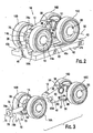
- the wheel assembly 10 further comprises at least another wheel 16 connected with the axle 14. More specifically, as indicated in Figs. 2 and 12, the axle 14 has first and second opposing ends 14a, 14b, the axle centerline 22 extends generally between the ends 14a, 14b, and the first wheel 16, hereinafter 16A, is connected with the axle 14 proximal to the first end 14a.
- the other or "second” wheel 16B is connected with the axle 14 proximal to the second axle end 14b and is configured to rotate generally about the axle centerline 22 such that when the second wheel 16B is disposed generally upon the base surface S, the second wheel 16B also rolls with respect to the base surface S so as to at least partially mobilize the vehicle 1, i.e., in conjunction with at least the "first" wheel 16A.
- the second wheel 16B is displaceable laterally within the same second plane P 2 (i.e., about second axis 20) as the first wheel 16A, as depicted in Fig. 10.
- the second wheel 16B is displaceable longitudinally within a third vertical plane (not shown) that is spaced from and extends substantially parallel with respect to the first plane P 1 .
- the axle 14 pivots about the second axis 20 so that both wheels 16A, 16B remain generally disposed upon the base surface S, as discussed in detail below.
- a base surface S having two laterally-extending, angled surface sections S 1 , S 2 that converge in inwardly-upward directions (i.e., sloped upwardly towards the surface center), such as with a "crowned" road bed or surface
- the axle 14 of each wheel assembly 10 connected with one side, e.g., side 6B, of the vehicle 1 angularly displaces outwardly in a first angular direction A 1 about the associated second axis 20.
- axle(s) 14 of the wheel assemblies 10 connected with the other side, i.e., side 6A, of the vehicle 1 each angularly displace outwardly in a second, opposing angular direction A 2 about the associated second axis 20, such that all the wheels 16A, 16B on the vehicle 1 remain generally disposed upon the base surface S, through contact with the belt 42 as discussed below.
- axle 14 of each wheel assembly 10 located on one side, e.g., side 6B, of the vehicle 1 each angularly displace inwardly in the second direction A 2 about the associated second axis 20.
- the axle(s) 14 of the assembl(ies) 10 located on the other side, i.e., side 6A, of the vehicle 1 each angularly displace inwardly in the first direction A 1 about the associated second axis 20 to maintain the wheels 16A, 16B disposed generally upon the base surface S.
- the chassis 2 will displace in a first angular direction about the longitudinal centerline 5 and generally toward the inclined surface section.
- the axle 14 of each wheel assembly 10 located on the horizontal surface section angularly displaces in a second, opposing angular direction about the associated second axis 20 in order to maintain the wheels 16A, 16B of each such wheel assembly 10 generally disposed upon the base surface S.
- the described movement of the chassis 2 and wheel assemblies 10 may be depicted by rotating either Fig. 13 or Fig. 14 so that one of the surface sections S 1 , S 2 or S 3 , S 4 shown in Fig. 13 or Fig. 14, respectively, is generally horizontal.
- each axle 14 on either or both sides 6A, 6B of the vehicle 1 pivot as required about the associated second axes 20 in the angular directions A 1 or A 2 and by the angular displacement(s) necessary to ensure that all wheels 16 connected with the vehicle 1 remain in contact with the ground/base surface S (i.e., through contact of the belt 42).
- each axle 14 pivots separately and independently of all the other axles 14 so that any particular axle 14 angularly displaces about the associated second axis 20 as necessary to ensure that the associated wheel assembly 10 is able to negotiate the specific section of the base surface S over which the assembly 10 travels.
- angular displacement of the axle 14 about the second axis 20 permits one of the two wheels, e.g., wheel 16A, to roll upon the offset section So as the other one of the two wheels, e.g., wheel 16B, rolls upon the remaining surface section S R .
- the wheel assembly 10 preferably further comprises another axle 26 connected with the frame 12 and at least one and preferably two other wheels 16C and 16D connected with the other axle 26.
- the other or "second" axle 26 is connected with the frame 12 so as to be spaced from the "first" axle 14 and is configured to be pivotable about a third axis 30 extending generally perpendicularly with respect to the first axis 18.
- the third axis 30 is at least parallel to, and is preferably collinear with, the second axis 20.
- the second axle 26 has a longitudinal centerline 32 extending generally perpendicularly with respect to the third axis 30.
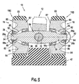
- the other or "third" and “fourth” wheels 16C, 16D are each connected with the second axle 26, preferably to each opposing axle end 26a, 26b (see Fig. 5), and are configured to rotate generally about the second axle centerline 32.
- the third and fourth wheels 16C, 16D are disposed upon the base surface S
- the two wheels 16C, 16D are rollable with respect to the base surface S so as to at least partially mobilize the vehicle 1, i.e., in combination with the first and second wheels 16A, 16B, respectively.
- the third wheel 16C is displaceable longitudinally within the same first vertical plane P 1 (i.e., about first axis 18) as the first wheel 16A, as depicted in Fig. 9, while the fourth wheel 16D is displaceable within the same third plane (not shown) as the second wheel 16C, which extends parallel to the first plane P 1 .
- the third and fourth wheels 16C, 16D are displaceable laterally within a fourth vertical plane (not shown) spaced from and extending substantially parallel with respect to the second plane P 2 shown in Fig. 10.
- the wheel assemblies 10 are able to maintain all four of the wheels 16A, 16B, 16C and 16D generally disposed upon the base surface S whenever the vehicle 1 travels over obstacles O or the chassis 2 pivots about the lateral centerline 7. Referring specifically to Fig.
- each wheel assembly 10 pivots as required about the associated first axis 18 to maintain all the wheels 16 of the particular assembly 10 in contact with the surface S.
- the vehicle 1 preferably has two wheel trains 36A, 36B each connected or mounted to a separate one of the sides 6A, 6B, respectively, of the tractor chassis 2.
- the two wheel trains 36A, 36B are generally identically constructed, but are arranged on the chassis 2 so as to be oppositely oriented with respect to the longitudinal centerline 5.
- each wheel train 36A, 36B preferably includes at least one and preferably three of the wheel assemblies 10, a drive wheel 28 and an idler wheel 34 (or a second drive wheel (not shown)).
- each wheel train 36A, 36B preferably includes a generally rectangular frame 29 extending longitudinally along and attached to each side 6A, 6B of the chassis 2, preferably by means of a plurality of laterally extending connective plates 33 (only one shown on each side 6A, 6B).
- the wheel assemblies 10 (and the other wheels 28, 34) of each wheel train 36A, 36B are attached to each frame 29, preferably by means of pin shafts 35 (as discussed below) so as to be pivotally connected with the vehicle 1.
- the vehicle 1 may be provided with a plurality of stub shafts 37 configured to rotatably connect each one of the wheel assemblies 10 directly to the vehicle chassis 2, as shown in Fig. 12.
- the pin shafts 35 or stub shafts 37 each establish the preferred locations of the second and third axes 20, 30, respectively, and the axle centerlines 22, 32 with respect to the vehicle 1, as discussed above.
- a separate endless belt 42 is disposed about all the wheels 16A, 16B, 16C, 16D, and preferably around wheels 28 and 34, of each wheel train 36A or 36B.
- Each belt 42 has an inner circumferential surface 43 and an opposing, outer circumferential surface 44, the four preferred wheels 16A, 16B, 16C and 16D of the wheel assembly 10 being contactable with the belt inner surface 43.
- the wheels 16A, 16B, 16C and 16D are generally disposed upon the base surface S when the belt outer surface 44 contacts the base surface S.
- the wheels 16A, 16B, 16C, 16D roll upon the inner surface 43 of the associated belt 42 as the belt 42 circulates about the wheel train 36A or 36B to mobilize the vehicle 1. More specifically, the first wheel 16A and the third wheel 16C roll upon an outer section 43a of the belt inner surface and the second wheel 16B and the fourth wheel 16D roll' upon a belt inner surface portion 43b, the two belt sections 43a, 43b being separated by an annular projection or ridge 41.
- the ridge 41 is disposeable between the each wheel in the pair of wheels 16A, 16B and 16C, 16D mounted to each axle 14, 26, respectively so as to retain the belt 42 disposed upon the associated wheel train 36A or 36B.
- each frame 12 of each wheel assembly 10 essentially functions to connect at least one and preferably the four wheels 16A, 16B, 16C and 16D with the vehicle 1 and as such may be considered to be a "connective member" 12, as discussed in further detail below.
- each frame 12 primarily includes a complex-shaped solid block 46 configured to be connected with the vehicle 1 and to connect the two preferred axles 14 and 26 to the frame 12.
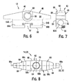
- the block 46 is preferably formed having an upper, crowned or angled surface 48, front and rear generally flat, parallel surfaces 50, 52, respectively, two inwardly stepped side surfaces 54A, 54B and a generally flat lower surface 56 with a central channel 57 extending between the front and rear surfaces 50 and 52, respectively.
- the frame block 46 preferably has a central bearing opening 58 configured to receive one of the vehicle shafts 35 or 37 so as to pivotally connect the frame 12 with the vehicle 1.
- the central opening 58 is provided by a journal bearing sleeve or bushing 59 disposed in a through hole extending between the front and rear surfaces 50, 52 of the block 46.
- the frame 12 may include a mounting shaft (not shown) fixedly or rotatably attached to the block 46 and configured to connect with an appropriate component on the vehicle 1, such as a bearing assembly or a socket (neither shown).
- the frame block 46 also preferably includes two generally circular, side bearing openings 60A, 60B extending into the block 46 from each side surface 54A, 54B and to the central channel 57. As such, each side opening 60A, 60B extends generally perpendicularly with respect to the central bearing opening 58.
- Each side bearing opening 60A, 60B is sized to receive a separate pivot shaft 72 preferably used to pivotally connect each one of the axles 14, 26 to the frame block 46, as described below.
- the frame 12 may be formed in any desired manner that enables the frame 12 to be pivotally connected to the vehicle 1 and at least one axle 14 to be pivotally connected to the frame 12.
- the block 46 may be formed in another appropriate shape, such as substantially square or rectangular and/or may be comprised as an assembly of separate blocks, as opposed to a single solid block.
- the frame 12 may be formed as an assembly of connected plates and/or bars with suitable openings, such as provided by insert bushings, configured to connect with the shaft 35 or 37 and the axle(s) 14 (and 26), as discussed above and in further detail below.
- the frame 12 may be provided by a block, a truss or a plate/bar assembly having shafts or a combination of shaft(s) and opening(s) for rotatable connection with the vehicle 1 and the wheels 16A, 16B, 16C, 16D (alternative structures not shown).
- the present invention encompasses these and all other appropriate alternative constructions of the frame 12 that enable the wheel assembly 10 to function generally as described herein.
- each wheel assembly 10 is preferably generally identically constructed and each has a central portion 62 and an opening 64 extending into, and preferably through, the central portion 62.
- the axle opening 64 is configured to receive a portion of a pivot shaft 72 (as described below) to pivotally connect the axle 14 or 26 with the frame 12, as discussed in further detail below.
- each axle 14, 26 is formed of an elongated body 65 including a generally rectangular block 66 providing the central portion 62 and two wheel shafts 68 each extending from an opposing side of the central block 66.
- a tubular sleeve or bushing 70 is preferably disposed within the central opening 64 and functions as a journal bearing to facilitate pivotal movement of the axle 14 or 26 upon a particular pivot shaft 72, as discussed below.
- each wheel shaft 68 is preferably formed as a generally circular bar 69 having an outer, free end 68a and an inner end 68b integrally formed with the central block 66.
- the centerline 22 or 32 of each axle 14, 26, respectively, preferably extends longitudinally through the body 65 between the outer ends 68a of the two wheel shafts 68.
- each bar 69 is stepped or tapered so as to be form several circular shaft sections with outside diameters (none indicated) that progressively decrease from the inner end 68b to the outer end 68a.
- each shaft portion 68 is configured to extend through the central opening 85 of a separate one of the bogie wheels 16A, 16B, 16C or 16D to rotatably mount the wheels 16A, 16B, 16C and 16D to the axles 14 or 26, as described in further detail below.
- the central block 66 and the two wheel shafts 68 are all integrally formed or connected together, such that the axles 14, 16 are each of one piece construction.
- the axles 14, 26 may be formed of multiple separate pieces attached together by appropriate means, such as by welding or threadably attaching two separate shaft 68 to the central block 66.
- wheel shafts 68 may alternatively be rotatably connected with the central block 66, for example by bearing assemblies, such as if the bogie wheels 16A, 16B, 16C and 16D are fixedly attached to the shafts 68 (structure not shown).
- the wheel assembly 10 further comprises at least one and preferably two pivot shafts 72.
- Each pivot shaft 72 has a first portion 74 connected with the frame 12 and a second portion 76 spaced from the first portion 74 and disposeable within the opening 64 of one of the axles 14 or 26.
- the pivot shafts 72 each pivotally connect a separate one of the axles 14 or 26, with the frame 12, as discussed above and in further detail below.
- each shaft 72 has a longitudinal centerline 75 extending generally between the first and second portions 74, 76, which each provide a separate one of the second and third axes 20, 30, respectively.
- each pivot shaft 72 is formed as a generally cylindrical bar 77 that includes the first and second shaft portions 74, 76, respectively, and having substantially circular cross-sections in directions perpendicular to the centerline 75.
- the bars 77 are each sized to fit within one of the frame side openings 60A or 60B with a clearance or interference fit to connect the shaft 72 respectively, with the frame 12.
- each bar 77 has a threaded hole 79 disposed proximal to the end of the first shaft portion 74.
- the threaded holes 79 are each engageable by a separate bolt 81 extending into the frame block 46 from the front surface 50.
- the bolts 81 releasably secure the pivot shafts 72 to the frame 12, but the shafts 72 may be alternatively non-releasably or fixedly attached to the frame block 46, such as for example, by rivets or weldment material (neither shown).
- the pivot shafts 72 each include a generally square or rectangular retainer plate 78 disposed about the bar 77 proximal to the outer end of the second shaft portion 76.
- the retainer plates 78 each function to retain the preferred axles 14, 26 slidably disposed upon the second portion 76 of the associated pivot shaft 72, as described below.
- each plate 78 has an upper edge 78a configured to abut a downward-facing section of the proximal stepped side surface 54A or 54B when the pivot shaft 72 is disposed within the associated side opening 60A or 60B.
- the plate upper edges 78a thereby function to prevent the pivot shafts 72 from rotating within the frame opening 60A or 60B so as to reduce the stress potentially applied to the bolts 80.
- each axle 14 or 26 is connected with the frame 12 by inserting the associated pivot shaft 72 through the axle central opening 64 until the axle block 66 is disposed about the shaft second portion 76 and against the inner surface 78b of the retainer plate 78.
- each shaft first portion 74 may then be inserted into the associated frame side opening 60A or 60B, and then secured therein as discussed above, so as to rotatably connect the respective axles 14, 26 to the frame 12.
- the axle bearing sleeves 70 are rotatably slidable about the outer circumferential surface of the pivot shaft second portion 76, to enable each axle 14, 26 to pivot about the second axis 20 or third axis 30, respectively, which extends through the associated shaft 72.
- the retainer plates 78 each loosely "sandwich" the axle central block 66 between the plate inner surface 78b and the portion of the frame block outer side surface 54A or 54B about the proximal side opening 60A, 60B, respectively. Thereby, the retainer plates 78 maintain the two axles 14 and 26 slidably retained upon the associated pivot shafts 72.
- each axle 14, 26 may be connected with the frame 12 by means of a bearing assembly or a U-joint (neither shown) pivotally attached to the frame 12.
- the axles 14, 26 may each be disposed within or fixedly attached to a block, frame or other structure/component (none shown) pivotally attached to the frame 12.
- the scope of the present invention encompasses these and all other appropriate structures or means for pivotally connecting the axles 14 and 26 with the frame 12 and is in no means limited by such connection means.
- each of the bogie wheels 16A, 16A, 16B, 16C and 16D are preferably substantially identically constructed and each is formed as a generally conventional bogie wheel 80 used with a wheeled paver 1.
- each wheel 80 includes wheel body 87 and a tire 83 disposed circumferentially about the body 87.
- the body 87 is preferably formed of a hub portion or hub 82, a circumferential rim portion or rim 84 and a radial flange portion 86 extending between and integrally connecting the hub 82 and rim 84.
- the hub 82 includes the central opening 85 configured to receive one wheel shaft 68 of an axle 14 or 26 so as to rotatably attach the wheel 80 to the particular axle 14, 26.
- each wheel 80 includes two roller bearings 90, 92 disposed within the central opening 85 on opposing sides of the hub 82. The bearings 90, 92 facilitate rotation of the wheel 80 when mounted upon the axle 14 or 26, in the following manner.
- the wheels 80 are mounted to an axle 14 or 26, by inserting one of the axle wheel shafts 68 through the wheel hub opening 85 until the inner bearing 90 abuts a shoulder section 68c of the shaft 68.
- the outer bearing 92 is inserted over the shaft 68 until the bearing 92 abuts a radial shoulder 82a of the hub 82, and then an end cap 94 is attached to the shaft outer end 68a so as to secure the wheel 80 upon the shaft 68.
- the wheel 80 is rotatable about the centerline 22 or 32 of the particular axle 14, 26, respectively, so as to be rollable upon a surface to mobilize the vehicle 1.
- the wheels 15A, 16B, 16C and 16D may be constructed in any appropriate manner and the scope of the present invention is not in any manner limited by the structure of the wheels 16.
- each wheel assembly 10 is constructed or assembled by mounting the four wheels 16A, 16B, 16C, 16D to the two axles 14, 26, and then connecting each of the two axles 14, 26 to the frame block 46 to form the complete wheel assembly 10, each of these steps being described in detail above.
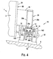
- the wheel assembly 10 is preferably mounted to the vehicle 1 by inserting a pin shaft 35 through the central frame opening 58 and then fixedly attaching the pin shaft 35 to one of the wheel train frames 29, such that the upper portion of the frame 12 is disposed between opposing frame walls 29a, 29b, as best shown in Fig. 4.
- each free end 35a of the pin shaft 35 is secured to one of a pair of aligned attachment plates 31 extending from each frame wall 29a, 29b, preferably by threaded fasteners 96.
- the frame 12 may be slidably mounted onto a vehicle stub shaft 37, as discussed above, and retained thereon by appropriate means such as a retainer plate or end cap (neither shown) secured to the shaft 37.
- the frame bushing 59 is rotatably slidable about the shaft outer circumferential surface 35a (Fig. 4) or 37a (Fig. 12), thereby enabling the frame 12 and the connected wheels 16A, 16B, 16C, and 16D to pivot about the first axis 18.
- each wheel assembly 10 when each wheel assembly 10 is connected with the vehicle 1, the second axis 20 of each assembly 10 is spaced a substantial distance D s from, and extends generally parallel with respect to, the longitudinal centerline 5 (each axis 5 and 20 extending perpendicularly through Figs. 12 and 13).
- the wheel assembly 10 of the present invention is clearly distinguishable from a wheel assembly having one or more axles mounted generally at or near the longitudinal centerline of a vehicle so as to be pivotable about the centerline or an axis proximal to the centerline (structure not shown).
- a paver vehicle 1 is provided with the following advantages over pavers having previous known wheel assemblies, as described in the Background Section above.
- the axles 14 and 26 each pivot about the second and third axes 20, 30, respectively, as necessary to ensure that the wheels 16A, 16B, 16C and 16D remain in contact with the base surface S.
- the weight of the vehicle 1 is distributed generally evenly between the four wheels 16A, 16B, 16C and 16D of each wheel assembly 10, as opposed to being concentrated on the two inner wheels 16B, 16D when traversing a positive slope (Fig.
- axles 14, 26 each pivot respectively about the second axis 20 and the third axis 30.
- Such axle movement enables one wheel (e.g., 16A) to vertically displace upwardly or downwardly as necessary to negotiate or travel over the obstacle or depression, while the other wheel (e.g., 16B) mounted on the same axle 14 or 26 remains in contact with the surface S (i.e., through the belt 42), as shown for example in Fig. 12.
Landscapes
- Engineering & Computer Science (AREA)
- Chemical & Material Sciences (AREA)
- Combustion & Propulsion (AREA)
- Transportation (AREA)
- Mechanical Engineering (AREA)
- Handcart (AREA)
- Road Paving Machines (AREA)
- Automatic Cycles, And Cycles In General (AREA)
Claims (16)
- Pflasterfahrzeug (1) enthaltend:eine Zugmaschine (8), die ein Fahrgestell (2) mit einem vorderen Ende (3), einem hinteren Ende (4) und zwei beabstandeten Seiten (6A, 6B) hat, die sich zwischen dem vorderen und dem hinteren Ende erstrecken;einen Abstreicher (9), der vom hinteren Ende der Zugmaschine gezogen wird;mindestens eine Radgruppe (10), die mit jeder Seite (6A, 6B) des Fahrgestells verbunden ist; undeinen Endlosriemen (42), der um jede Radgruppe geführt ist, wobei jeder Riemen eine innere Umfangsoberfläche (43) und eine entgegen gesetzte, äußere Umfangsoberfläche (44) hat,wobei jede Radgruppe (10) zum Bewegen des Pflasterfahrzeugs (1) auf einem Untergrund (S) angepasst ist und enthält:einen Achsschenkel (14, 26), der mit dem Fahrgestell verbunden ist und eine Längsmittellinie (22, 32) besitzt, wobei der Achsenschenkel so gestaltet ist, dass er um eine erste Achse (18) schwenkt; underste und zweite Räder (16, 16A-D), die mit dem Achsenschenkel nahe ihrer ersten und zweiten entgegen gesetzten Enden (14a, 14b) verbunden sind, wobei jedes Rad, in Berührung mit der inneren Riemenoberfläche bringbar ist und gestaltet ist zum Rotieren im Wesentlichen um die Längsmittellinie des Achsenschenkels so, dass die Räder auf der inneren Riemenoberfläche rollen, wenn der Riemen um die Radgruppe zum Bewegen des Fahrzeugs umläuft;wobei der Achsenschenkel (14, 26; 14' 14") darüber hinaus so gestaltet ist, dass er um eine zweite Achse (20) schwenkt, wobei sich die zweite Achse im Wesentlichen senkrecht bezüglich der ersten Achse (18) erstreckt und sich im Wesentlichen auch senkrecht bezüglich der Längsmittellinie des Achsenschenkels erstreckt und diese so schneidet, dass die Räder (16, 16A-D) vertikal versetzbar um die erste Achse (18) sind und/oder vertikal versetzbar um die zweite Achse (20) sind.
- Pflasterfahrzeug (1) nach Anspruch 1, weiter enthaltend einen Rahmen oder ein Bindeglied (12), das schwenkbar mit dem Fahrzeug (1) verbunden ist, dass es winkelförmig schwenkbar um die erste Achse (18) ist, wobei der Achsenschenkel (14, 26) schwenkbar mit dem Rahmen verbunden ist, dass er winkelförmig um die zweite Achse (20) schwenkbar ist.
- Pflasterfahrzeug (1) nach Anspruch 1 oder 2, wobei die erste und die zweite Achse (18, 20) im Wesentlichen horizontal sind.
- Pflasterfahrzeug (1) nach Anspruch 2 oder 3, wobei jede Radgruppe (10) so gestaltet ist, dass winkelförmiges Schwenken des Rahmens oder des Bindeglieds (12) um die erste Achse (18) die Räder (16, 16A-D) bezüglich des Fahrzeugs (1) im Wesentlichen innerhalb einer ersten Ebene (P1) versetzt und ein winkelförmiges Schwenken des Achsschenkels (14, 26) um die zweite Achse (20) die Räder bezüglich des Fahrzeugs im Wesentlichen innerhalb einer zweiten Ebene (P2) versetzt, wobei die zweite Ebene im Wesentlichen senkrecht zu der ersten Ebene ist.
- Pflasterfahrzeug (1), nach einem der vorhergehenden Ansprüche, wobei:sich die zweite Achse (20) im Wesentlichen horizontal und senkrecht zur Wagenachse erstreckt; undjede Radgruppe (10) angepasst ist, dass ein winkelförmiges Schwenken des Achsschenkels (14, 26) um die zweite Achse die Räder (16, 16A-D) vertikal gegeneinander versetzt.
- Pflasterfahrzeug (1) nach einem der vorhergehenden Ansprüche, wobei, wenn der Untergrund (S) einen abweichenden Teil (O) hat, der vertikal beabstandet vom übrigen Teil des Untergrundes ist, der Achsschenkel (14, 26) angepasst ist, winkelförmig um die zweite Achse (20) zu schwenken, so dass eines der zwei Räder (16, 16A-D) der Radgruppe (10) auf den abweichenden Teil des Untergrunds bringbar ist, wohingegen das andere der zwei Räder im Wesentlichen auf dem übrigen Teil des Untergrunds angebracht ist.
- Pflasterfahrzeug (1) nach einem der Ansprüche 2 bis 6, weiter enthaltend:einen weiteren Achsschenkel (14, 26), der mit dem Rahmen (12) so verbunden ist, dass er beabstandet zum Achsschenkel (14, 26) ist, wobei der andere Achsschenkel so gestaltet ist, dass er schwenkbar um eine dritte Achse (30) ist und sich im Wesentlichen senkrecht bezüglich der ersten Achse (18) erstreckt, wobei der andere Achsschenkel eine Längsmittellinie (22, 32) hat, sich im Wesentlichen senkrecht bezüglich der dritten Achse erstreckt; undzwei Räder (16, 16A-D), die mit dem anderen Achsschenkel verbunden sind und zum Rotieren im Wesentlichen um die Längsmittellinie des anderen Achsschenkels gestaltet sind und im Wesentlichen auf dem Untergrund (S) verteilbar sind.
- Pflasterfahrzeug (1) nach einem der Ansprüche 2 bis 7 weiter enthaltend eine drehbare Welle (72), die mit dem Rahmen (12) verbunden ist und eine Längsmittellinie (75) besitzt, welche die zweite Achse (20) darstellt, wobei der Achsschenkel (14, 26), mit der Welle so verbunden ist, dass er im Wesentlichen um die Längsmittellinie der Welle schwenkbar ist.
- Pflasterfahrzeug (1) nach einem der Ansprüche 2 bis 9, wobei der Rahmen (12) im Wesentlichen als fester Block (46) gestaltet ist, wobei der Block eine Öffnung (58) hat, die gestaltet ist, eine Fahrzeugwelle (35) aufzunehmen, die angepasst ist, den Rahmen mit dem Fahrzeug (1) schwenkbar zu verbinden.
- Pflasterfahrzeug (1) nach Anspruch 8 oder 9, wobei:der Achsschenkel (14, 26) einen mittleren Bereich (62) und eine Öffnung (64) hat, die sich in den mittleren Bereich erstreckt; unddie drehbare Welle (72) einen ersten Bereich (74) hat, der mit dem Rahmen (12) verbunden ist, einen zweiten Bereich (76), der beabstandet zum ersten Bereich und innerhalb der Achsschenkelöffnung angelegt ist, um den Achsschenkel schwenkbar mit dem Rahmen zu verbinden, und sich die Längsmittellinie im Wesentlichen zwischen dem ersten und dem zweiten Bereich erstreckt.
- Pflasterfahrzeug (1) nach einem der vorhergehenden Ansprüche, wobei jeder Achsschenkel (14, 26) angepasst ist, um die zweite Achse (18) separat und unabhängig von allen anderen Achsschenkeln (14, 26) zu schwenken und sich winkelförmig zu versetzen.
- Pflasterfahrzeug (1) nach einem der vorhergehenden Ansprüche, wobei, wenn das Fahrgestell (2) um eine seitliche Mittellinie (7) schwenkt, jede Radgruppe (10) angepasst ist, so weit wie nötig um seine erste Achse (18) zu schwenken, um alle Räder (16, 16A-D) der Radgruppe in Berührung mit dem Untergrund (S) zu lassen.
- Pflasterfahrzeug (1) nach einem der Ansprüche 1 bis 12, wobei:die ersten und zweiten Achsen (18, 20) jeweils im Wesentlichen horizontal gegenüber dem Untergrund (S) sind, die erste Ebene (P1) im Wesentlichen vertikal gegenüber dem Untergrund ist und sich im Wesentlichen parallel zu den beiden Seiten und im Wesentlichen senkrecht bezüglich des vorderen und hinteren Endes erstreckt, und die zweite Ebene (P2) im Wesentlichen vertikal gegenüber dem Untergrund ist und sich im Wesentlichen parallel zum vorderen und hinteren Ende und im Wesentlichen senkrecht bezüglich der beiden Seiten erstreckt.
- Pflasterfahrzeug (1) nach einem der vorhergehenden Ansprüche, wobei jede Radgruppe (10) innerhalb einer Radreihe (36A, 36B) angebracht ist, die ein Antriebsrad (28) und ein Leerlaufrad (34) oder ein zweites Antriebsrad enthält, wobei der Endlosriemen (42) um alle Räder (16, 16A-D, 28, 34) der Radreihe geführt ist.
- Pflasterfahrzeug (1) enthaltend:ein Fahrgestell (2), das ein vorderes Ende (3), ein hinteres Ende (4), erste und zweite gegenüberliegende Seiten (6A, 6B) und eine Längsmittellinie (5) hat, die sich zwischen dem vorderen und dem hinteren Ende erstreckt;eine erste Radgruppe (10), die mit der ersten Seite des Fahrgestells (6A) verbunden ist und einen Achsschenkel (14, 26) enthält, wobei der Achsschenkel einen mittleren Bereich (62), zwei gegenüberliegende Enden (14a, 14b, 68a) und eine Mittellinie (22, 32) hat, die sich zwischen den beiden Enden erstreckt, zwei Räder (16, 16A-D), die jeweils beweglich mit einem separaten Ende des Achsschenkels so verbunden sind, dass sie schwenkbar um die Mittellinie des Achsschenkels sind, und einen Endlosriemen (42), der um die Räder geführt ist; undeine zweite Radgruppe (10), die mit der zweiten Seite des Fahrgestells (6B) verbunden ist, so dass die ersten und zweiten Gruppen auf den gegenüberliegenden Seiten der Fahrgestellmittellinie angeordnet sind, wobei die zweite Radgruppe einen Achsschenkel (14, 26) enthält, wobei der Achsschenkel einen mittleren Bereich (68), zwei gegenüberliegende Enden (14a, 14b, 68a) und eine Mittellinie (22, 32) hat, die sich zwischen den beiden Enden erstreckt, zwei Räder (16, 16A-D) die jeweils beweglich mit einem separaten Ende des Achsschenkels so verbunden sind, dass sie um die Mittellinie des Achsschenkels schwenkbar sind, und einen Endlosriemen (42), der um die Räder geführt ist;wobei jedes der zwei Räder (16, 16A-D) gegeneinander vertikal schwenkbar um die erste Achse (18) ist, und
beide Achsschenkel (14, 26) gestaltet sind, seitlich um eine zweite Achse (20) zu schwenken, die sich durch den mittleren Bereich (62) und die Mittellinie (22, 32) jedes Achsschenkels erstreckt, dessen horizontale Achse im Wesentlichen parallel zur Längsmittellinie des Fahrgestells (5) ist, so dass jedes der Räder (16, 16A-D) vertikal schwenkbar um die erste Achse (18) und/oder vertikal schwenkbar um die zweite Achse (20) ist. - Pflasterfahrzeug (1) nach Anspruch 15 wobei, wenn das Fahrzeug einen Untergrund (S) überquert, der zwei zusammenlaufende, verwinkelte Flächenteile (S1, S2; S3, S4) hat, so dass die erste Radgruppe (10) auf einem der zwei Flächenteile (S1, S3) verteilt ist und die zweite Radgruppe im Wesentlichen auf dem anderen der zwei Flächenteile (S2; S4) verteilt ist, der Achsschenkel (14, 26) der ersten Radgruppe angepasst ist, sich winkelförmig in eine erste Winkelrichtung (A1) um die zweite Achse (20) der ersten Radgruppe zu schwenken, während der Achsschenkel (14, 26) der zweiten Radgruppe winkelförmig um eine zweite, entgegengesetzte Winkelrichtung (A2) um die zweite Achse (20) der zweiten Radgruppe schwenkt, so dass die ersten zwei Räder der ersten Radgruppe im Wesentlichen auf dem einen Flächenteil (S1, S3) verteilt sind und die zwei Räder der zweiten Radgruppe im Wesentlichen auf dem anderen Flächenteil (S2; S4) verteilt sind.
Applications Claiming Priority (3)
| Application Number | Priority Date | Filing Date | Title |
|---|---|---|---|
| US10/192,127 US6712549B2 (en) | 2002-07-09 | 2002-07-09 | Double-axis oscillating bogie wheels |
| US192127 | 2002-07-09 | ||
| PCT/US2003/021470 WO2004005118A1 (en) | 2002-07-09 | 2003-07-09 | Double-axis oscillating bogie wheels |
Publications (2)
| Publication Number | Publication Date |
|---|---|
| EP1551688A1 EP1551688A1 (de) | 2005-07-13 |
| EP1551688B1 true EP1551688B1 (de) | 2006-09-20 |
Family
ID=30114278
Family Applications (1)
| Application Number | Title | Priority Date | Filing Date |
|---|---|---|---|
| EP03763402A Expired - Lifetime EP1551688B1 (de) | 2002-07-09 | 2003-07-09 | Pflasterfahrzeug |
Country Status (7)
| Country | Link |
|---|---|
| US (1) | US6712549B2 (de) |
| EP (1) | EP1551688B1 (de) |
| CN (1) | CN1681701A (de) |
| AU (1) | AU2003248897A1 (de) |
| DE (1) | DE60308540T2 (de) |
| RU (1) | RU2005103238A (de) |
| WO (1) | WO2004005118A1 (de) |
Families Citing this family (46)
| Publication number | Priority date | Publication date | Assignee | Title |
|---|---|---|---|---|
| US7740084B2 (en) | 2000-05-02 | 2010-06-22 | Lyn Rosenboom | Agricultural implement frame, track assembly and cart |
| US7380892B2 (en) * | 2001-05-02 | 2008-06-03 | Lyn Rosenboom | Track assembly with idler wheels and cart incorporating same |
| US20050058507A1 (en) * | 2003-09-17 | 2005-03-17 | Cedarapids, Inc. | Multi-use paving tractor with tool attachments |
| US20070065230A1 (en) * | 2003-09-17 | 2007-03-22 | Cedarapids, Inc. | Self Propelled Remix Machine with Conveyor |
| US7458747B2 (en) * | 2003-09-17 | 2008-12-02 | Cedarapids, Inc. | Frame raising multi-use paving tractor with blind mateable quick connecting tool attachments |
| DE602004009208T2 (de) * | 2003-11-11 | 2008-06-26 | Fargo Products, Llc | Gleiskettensystem für ein bodeneingriffsfahrzeug |
| DE602005011608D1 (de) | 2004-06-15 | 2009-01-22 | Terex Demag Gmbh | Laufrollenkonstruktion für die laufkette eines raupenfahrwerks |
| CA2582210A1 (en) * | 2006-03-22 | 2007-09-22 | Cedarapids, Inc. | Multi-stage modular road paving equipment and method of manufacture and sales |
| US8967737B2 (en) | 2010-06-30 | 2015-03-03 | Camoplast Solideal Inc. | Wheel of a track assembly of a tracked vehicle |
| US9505454B1 (en) | 2011-06-13 | 2016-11-29 | Camso Inc. | Track assembly for traction of an off-road vehicle |
| JP5818615B2 (ja) * | 2011-09-29 | 2015-11-18 | 住友建機株式会社 | 道路舗装機械の敷き均し装置 |
| BE1021152B1 (nl) * | 2013-06-05 | 2016-01-13 | Cnh Industrial Belgium Nv | Rubber rupsbandeenheid voor voertuig |
| US9457850B2 (en) | 2013-06-14 | 2016-10-04 | Unverferth Manufacturing Co., Inc. | Dual track |
| US9457854B2 (en) * | 2014-04-02 | 2016-10-04 | Unverferth Manufacturing Co., Inc. | Track assembly for farm implement |
| CA2916631C (en) * | 2015-01-02 | 2023-01-24 | Camso Inc. | Track system for traction of an off-road vehicle |
| US10065690B2 (en) * | 2015-04-03 | 2018-09-04 | Harris Corporation | Conformal suspension for unmanned ground vehicle |
| US10710652B2 (en) | 2015-05-29 | 2020-07-14 | Cnh Industrial America Llc | Rounded track idlers |
| US10875591B2 (en) * | 2015-08-04 | 2020-12-29 | Camso Inc. | Track system for traction of an agricultural vehicle travelling on fields and roads |
| US12123152B2 (en) | 2015-10-23 | 2024-10-22 | Ligchine International Corporation | Side-step concrete screeding apparatus |
| US11173971B2 (en) * | 2016-02-08 | 2021-11-16 | Camso Inc. | Tracked vehicle with adjustable track spacing |
| CN109080718A (zh) * | 2017-06-13 | 2018-12-25 | 天津乐农机械有限公司 | 一种农业用移动装置 |
| US11299220B2 (en) | 2017-07-11 | 2022-04-12 | Soucy International Inc. | Track assembly for a towed vehicle |
| GB201803700D0 (en) | 2018-03-08 | 2018-04-25 | Jotun As | Device |
| CN108674504B (zh) * | 2018-07-25 | 2023-12-08 | 江苏徐工工程机械研究院有限公司 | 车辆用模块化履带装置 |
| CN110758582A (zh) * | 2018-07-25 | 2020-02-07 | 韩伟发 | 仿形支重台车 |
| CN108674506A (zh) * | 2018-07-25 | 2018-10-19 | 徐工集团工程机械有限公司 | 车辆履带行走装置 |
| CA3054513A1 (en) | 2018-09-07 | 2020-03-07 | Soucy International Inc. | Vehicle and track system with pressure-adjustable wheels |
| US11162232B2 (en) | 2018-10-08 | 2021-11-02 | Ligchine International Corporation | Drive system for screeding concrete |
| US11560727B2 (en) | 2018-10-08 | 2023-01-24 | Ligchine International Corporation | Apparatus for screeding concrete |
| US11585049B2 (en) * | 2019-08-28 | 2023-02-21 | Caterpillar Paving Products Inc. | Overload support system for a paving machine screed assembly |
| CA3163884A1 (en) * | 2019-12-06 | 2021-06-10 | Camso Inc. | Track system for traction of a vehicle |
| US12269543B2 (en) | 2020-01-23 | 2025-04-08 | Soucy International Inc. | Suspended undercarriage assembly for a track system |
| WO2021149008A1 (en) | 2020-01-23 | 2021-07-29 | Soucy International Inc. | Suspended undercarriage assembly for a track system |
| EP4093656A4 (de) | 2020-01-23 | 2024-03-06 | Soucy International Inc. | Mehrteilige rahmenanordnung für ein schienensystem |
| CN111422270A (zh) * | 2020-04-17 | 2020-07-17 | 中国十七冶集团有限公司 | 一种履带型吊车支承轮结构 |
| CN111661183B (zh) * | 2020-04-29 | 2021-10-12 | 徐工集团工程机械有限公司 | 三角履带轮和工程车辆 |
| US12091110B2 (en) | 2020-09-18 | 2024-09-17 | Soucy International Inc. | Support structure for connecting at least one support wheel assembly to a frame member of a track system and track system having the same |
| CA3131066A1 (en) | 2020-09-18 | 2022-03-18 | Soucy International Inc. | Support structure for connecting at least one support wheel assembly to a frame of a track system and track system having the same |
| WO2022182755A1 (en) | 2021-02-23 | 2022-09-01 | Ligchine International Corporation | Swing boom concrete screeding apparatus |
| US12384475B2 (en) | 2021-06-29 | 2025-08-12 | Soucy International Inc. | Wheel assembly for track system, wheel assembly for track system of light-heavy duty vehicle and track system for light-heavy duty vehicle |
| US12378082B2 (en) | 2021-10-25 | 2025-08-05 | Ligchine International Corporation | Portable telescopic conveyor belt |
| CN114228852B (zh) * | 2022-01-07 | 2023-07-04 | 江苏徐工工程机械研究院有限公司 | 楼梯行走装置和机器人 |
| US12391321B2 (en) | 2022-01-17 | 2025-08-19 | Unverferth Manufacturing Co., Inc. | Track configuration for a farm implement |
| US12612124B1 (en) * | 2023-05-25 | 2026-04-28 | Lyn A. Rosenboom | Track assembly |
| US20250136204A1 (en) * | 2023-10-25 | 2025-05-01 | Soucy International Inc. | Articulation assembly for a vehicle with a track system |
| SE2451243A1 (en) * | 2024-12-05 | 2026-06-06 | Komatsu Forest Ab | Track assembly for a work machine and a work machine comprising said track assembly |
Family Cites Families (14)
| Publication number | Priority date | Publication date | Assignee | Title |
|---|---|---|---|---|
| DE550145C (de) | 1932-05-09 | Adolf Bleichert & Co Akt Ges | Gleiskettenfahrzeug, bei dem zwei Gleisketten durch einen zur UEbernahme der Last dienenden Quertraeger zu einem Fahrwerkspaar vereinigt sind | |
| DE604009C (de) | 1934-10-12 | Buckau R Wolf Akt Ges Maschf | Abstuetzung des Fahrgestellrahmens auf zwei Gleisketten | |
| US3275386A (en) * | 1964-08-04 | 1966-09-27 | Int Harvester Co | Crawler tractor suspension |
| US3343889A (en) * | 1964-08-04 | 1967-09-26 | Int Harvester Co | Crawler tractor suspension |
| US3455405A (en) | 1968-01-02 | 1969-07-15 | Pierre Parent | Multitrack snow vehicle |
| US3776326A (en) * | 1969-12-31 | 1973-12-04 | Blaw Knox Const Equipment | Paving machine |
| US3901616A (en) * | 1974-07-22 | 1975-08-26 | Kenneth J Greening | Self-propelled paver |
| US4166511A (en) | 1977-06-27 | 1979-09-04 | Caterpillar Tractor Co. | Four-track low ground pressure crawler vehicle |
| CA1120977A (en) * | 1978-10-03 | 1982-03-30 | Edwin W. Sankey | Frame structure for track-type vehicle |
| US4647116A (en) * | 1979-06-22 | 1987-03-03 | Riggers Manufacturing Co. | Crawler suspension system |
| US5409305A (en) * | 1992-08-17 | 1995-04-25 | Deere & Company | Undercarriage for a track laying vehicle |
| US5590977A (en) | 1995-05-25 | 1997-01-07 | Guntert & Zimmerman Constr. Div. Inc. | Four track paving machine and process of transport |
| US5639148A (en) * | 1996-04-17 | 1997-06-17 | Deere & Company | Undercarriage adjustment mechanism for a tracked vehicle |
| DE19857891A1 (de) * | 1998-12-15 | 2000-06-21 | Macmoter Spa | Raupenfahrzeug |
-
2002
- 2002-07-09 US US10/192,127 patent/US6712549B2/en not_active Expired - Fee Related
-
2003
- 2003-07-09 RU RU2005103238/11A patent/RU2005103238A/ru not_active Application Discontinuation
- 2003-07-09 EP EP03763402A patent/EP1551688B1/de not_active Expired - Lifetime
- 2003-07-09 AU AU2003248897A patent/AU2003248897A1/en not_active Abandoned
- 2003-07-09 WO PCT/US2003/021470 patent/WO2004005118A1/en not_active Ceased
- 2003-07-09 CN CNA038212080A patent/CN1681701A/zh active Pending
- 2003-07-09 DE DE60308540T patent/DE60308540T2/de not_active Expired - Fee Related
Also Published As
| Publication number | Publication date |
|---|---|
| EP1551688A1 (de) | 2005-07-13 |
| US6712549B2 (en) | 2004-03-30 |
| CN1681701A (zh) | 2005-10-12 |
| AU2003248897A1 (en) | 2004-01-23 |
| DE60308540D1 (de) | 2006-11-02 |
| US20040009038A1 (en) | 2004-01-15 |
| WO2004005118A1 (en) | 2004-01-15 |
| DE60308540T2 (de) | 2007-06-21 |
| RU2005103238A (ru) | 2005-08-10 |
Similar Documents
| Publication | Publication Date | Title |
|---|---|---|
| US6712549B2 (en) | Double-axis oscillating bogie wheels | |
| US7497642B2 (en) | Zero end clearance roller for a drum type compactor | |
| CA2337766C (en) | Modular track-laying system | |
| US12479523B2 (en) | Suspended undercarriage assembly for a track system | |
| CN206494021U (zh) | 非公路车辆 | |
| WO1995011816A1 (en) | Tracked vehicles and power drive apparatus for motivating tracked vehicles | |
| US7762372B2 (en) | Wheel unit for automotive vehicles | |
| RU2347707C2 (ru) | Приводимая ходовая часть с рулевым управлением | |
| US7108086B2 (en) | All wheel drive utility vehicle with bogey beam suspension | |
| US6520717B1 (en) | Walking beam roller apparatus | |
| US20060237251A1 (en) | Wheel unit for automotive vehicles | |
| JPH05286460A (ja) | 操舵式クローラ車 | |
| CA3219806A1 (en) | Wheel assembly, track system, and light-heavy duty vehicle | |
| CN113428214A (zh) | 一种臂式高空作业平台底盘 | |
| WO2025250113A1 (en) | New design for tractors and trailers | |
| JPS6143664Y2 (de) | ||
| US7121636B2 (en) | Endless track for paving vehicles | |
| JP2898542B2 (ja) | トレーラ | |
| RU2288106C1 (ru) | Колесо повышенной проходимости | |
| RU2164987C2 (ru) | Пневмоколесное ходовое устройство экскаватора | |
| JP2002173059A (ja) | クローラ足回り構造 | |
| RU171244U1 (ru) | ВЕЗДЕХОДНОЕ ТРАНСПОРТНОЕ СРЕДСТВО 8х8 | |
| JPH0744482Y2 (ja) | クローラベルト | |
| JPH0478086U (de) | ||
| AU2004202993A1 (en) | Wide based suspension |
Legal Events
| Date | Code | Title | Description |
|---|---|---|---|
| PUAI | Public reference made under article 153(3) epc to a published international application that has entered the european phase |
Free format text: ORIGINAL CODE: 0009012 |
|
| 17P | Request for examination filed |
Effective date: 20050209 |
|
| AK | Designated contracting states |
Kind code of ref document: A1 Designated state(s): AT BE BG CH CY CZ DE DK EE ES FI FR GB GR HU IE IT LI LU MC NL PT RO SE SI SK TR |
|
| AX | Request for extension of the european patent |
Extension state: AL LT LV MK |
|
| DAX | Request for extension of the european patent (deleted) | ||
| RBV | Designated contracting states (corrected) |
Designated state(s): DE FR GB SE |
|
| GRAP | Despatch of communication of intention to grant a patent |
Free format text: ORIGINAL CODE: EPIDOSNIGR1 |
|
| GRAS | Grant fee paid |
Free format text: ORIGINAL CODE: EPIDOSNIGR3 |
|
| RTI1 | Title (correction) |
Free format text: PAVING VEHICLE |
|
| GRAA | (expected) grant |
Free format text: ORIGINAL CODE: 0009210 |
|
| AK | Designated contracting states |
Kind code of ref document: B1 Designated state(s): DE FR GB SE |
|
| REG | Reference to a national code |
Ref country code: GB Ref legal event code: FG4D |
|
| REF | Corresponds to: |
Ref document number: 60308540 Country of ref document: DE Date of ref document: 20061102 Kind code of ref document: P |
|
| REG | Reference to a national code |
Ref country code: SE Ref legal event code: TRGR |
|
| ET | Fr: translation filed | ||
| PLBE | No opposition filed within time limit |
Free format text: ORIGINAL CODE: 0009261 |
|
| STAA | Information on the status of an ep patent application or granted ep patent |
Free format text: STATUS: NO OPPOSITION FILED WITHIN TIME LIMIT |
|
| 26N | No opposition filed |
Effective date: 20070621 |
|
| EUG | Se: european patent has lapsed | ||
| GBPC | Gb: european patent ceased through non-payment of renewal fee |
Effective date: 20070709 |
|
| PG25 | Lapsed in a contracting state [announced via postgrant information from national office to epo] |
Ref country code: SE Free format text: LAPSE BECAUSE OF NON-PAYMENT OF DUE FEES Effective date: 20070710 Ref country code: DE Free format text: LAPSE BECAUSE OF NON-PAYMENT OF DUE FEES Effective date: 20080201 |
|
| PG25 | Lapsed in a contracting state [announced via postgrant information from national office to epo] |
Ref country code: GB Free format text: LAPSE BECAUSE OF NON-PAYMENT OF DUE FEES Effective date: 20070709 |
|
| REG | Reference to a national code |
Ref country code: FR Ref legal event code: ST Effective date: 20080331 |
|
| PG25 | Lapsed in a contracting state [announced via postgrant information from national office to epo] |
Ref country code: FR Free format text: LAPSE BECAUSE OF NON-PAYMENT OF DUE FEES Effective date: 20070731 |