EP1552040B1 - Dichtungsystem für elektrolysezelle - Google Patents
Dichtungsystem für elektrolysezelle Download PDFInfo
- Publication number
- EP1552040B1 EP1552040B1 EP02795315A EP02795315A EP1552040B1 EP 1552040 B1 EP1552040 B1 EP 1552040B1 EP 02795315 A EP02795315 A EP 02795315A EP 02795315 A EP02795315 A EP 02795315A EP 1552040 B1 EP1552040 B1 EP 1552040B1
- Authority
- EP
- European Patent Office
- Prior art keywords
- limiter
- support
- leak limiter
- leak
- electrolytic cell
- Prior art date
- Legal status (The legal status is an assumption and is not a legal conclusion. Google has not performed a legal analysis and makes no representation as to the accuracy of the status listed.)
- Expired - Lifetime
Links
Images


Classifications
-
- C—CHEMISTRY; METALLURGY
- C25—ELECTROLYTIC OR ELECTROPHORETIC PROCESSES; APPARATUS THEREFOR
- C25C—PROCESSES FOR THE ELECTROLYTIC PRODUCTION, RECOVERY OR REFINING OF METALS; APPARATUS THEREFOR
- C25C3/00—Electrolytic production, recovery or refining of metals by electrolysis of melts
- C25C3/06—Electrolytic production, recovery or refining of metals by electrolysis of melts of aluminium
- C25C3/08—Cell construction, e.g. bottoms, walls, cathodes
- C25C3/10—External supporting frames or structures
-
- C—CHEMISTRY; METALLURGY
- C25—ELECTROLYTIC OR ELECTROPHORETIC PROCESSES; APPARATUS THEREFOR
- C25C—PROCESSES FOR THE ELECTROLYTIC PRODUCTION, RECOVERY OR REFINING OF METALS; APPARATUS THEREFOR
- C25C3/00—Electrolytic production, recovery or refining of metals by electrolysis of melts
- C25C3/06—Electrolytic production, recovery or refining of metals by electrolysis of melts of aluminium
- C25C3/22—Collecting emitted gases
Definitions
- the invention relates to the production of aluminum by igneous electrolysis. It relates more particularly to the means for confining gaseous effluents produced during electrolysis.
- Aluminum metal is produced industrially by igneous electrolysis, namely by electrolysis of alumina in solution in a bath of molten cryolite, called electrolyte bath, according to the well-known Hall-Héroult process.
- the electrolyte bath is contained in tanks, called “electrolysis cells", comprising a steel box, which is coated internally with refractory and / or insulating materials, and a cathode assembly located at the bottom of the tank.
- Anodes made of carbonaceous material are partially immersed in the electrolyte bath.
- the assembly formed by an electrolytic cell, its anodes and the electrolyte bath is called an electrolysis cell.
- a widely used solution consists in providing the electrolysis cells with an effluent collection device.
- This device covers the electrolysis tanks and comprises means of containment, which include in particular a rollover device, and means for suctioning and chemical treatment of the effluents.
- the known effluent treatment processes include the recovery of fluorinated gases by reaction with alumina.
- the cowling device comprises access means, such as covers, generally removable, and a casting door, which allow to intervene on the tank.
- the rollover device delimits a confined suction zone and in depression with respect to the ambient atmosphere, which makes it possible to effectively recover the effluents. This results in steady-state capture efficiencies of over 97% in the most modern industrial facilities, so that the rates of atmospheric emissions of gaseous fluorinated products are well below regulatory thresholds.
- the anodes are connected to an electrical power supply bar, located outside the collection device, via metal rods which pass through the device through openings in the device.
- the free space (or "clearance") left by the rods in these openings is not sealed to allow vertical and horizontal movements of the metal rods.
- Vertical displacements are frequent and allow, in particular, to compensate for the wear of anodes during electrolysis.
- Horizontal displacements generally come from the replacement of spent anodes.
- the free spaces between the anode rods and the inner edge of the passage openings constitute a rupture of confinement which is of small importance for each anode rod, but which becomes significant for all the anodes of a cell, and a fortiori for a series of several hundred cells.
- the present invention relates to a leak limiter adapted to reduce the confinement breakage from the passage openings of the anode rods. More specifically, the leakage limiter according to the invention is intended to limit the air and gas passages between the inside and the outside of the capture device of an aluminum production cell by igneous electrolysis through passage openings of the anode rods.
- the leakage limiter of an electrolysis cell according to the invention is characterized in that it comprises at least one support, able to surround all or part of an anode rod, and at least one sealing body.
- flexible device arranged on all or part of the periphery and intended to close all or part of the free space between the inner edge of the passage openings and the anode rod.
- the flexible body provides a certain seal around the anode rod and allows the maintenance of this seal, thanks to the flexibility of the body, despite inevitable variations in the position of the rod.
- the invention makes it possible to substantially limit gaseous exchanges by said free space.
- the support is advantageously in the form of notch in order to simplify the construction of the leak limiter and to allow lateral insertion of an anode rod through the opening of the notch.
- the subject of the invention is also an electrolysis cell comprising at least one leakage limiter according to the invention.
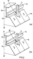
- an electrolysis cell (1) for the production of aluminum by the Hall-Héroult method typically comprises a tank (10), anodes (2) supported by the fixing means typically comprising a rod (3) and a multipode (4) and mechanically and electrically connected to an anode frame (5) by means of connection means (6).
- the anode rod (3) is typically of substantially rectangular or square section.
- the tank (10) comprises a steel box (7), lining elements (8) and a cathode assembly (9).
- the coating elements (8) and the cathode assembly (9) form, inside the tank (10), a crucible adapted to contain the electrolyte bath (11) and a sheet of liquid metal (12) .
- the electrolysis cell (1) also comprises a metal framework (13), which supports, in particular, the anode frame (5) in a mobile manner, and an effluent collection device comprising containment means (14, 15) and delimiting a confined interior space (16).
- the confinement means typically comprise removable hoods (14) and a fixed hood (15).
- the sensing device comprises openings (17) able to freely pass an anode rod (3).
- This opening usually takes the form of a slot to allow the insertion of an anode rod.
- the anodes (2) are generally introduced or removed from a lateral insertion electrolysis cell after removal of one or more covers (14). Therefore, the opening (17) is such that it allows a lateral insertion of the rod (3) of the anode (2), with or without longitudinal displacement thereof, that is to say with or without displacement thereof along the main axis of the cell.
- Figure 2 (b) schematically illustrates the positioning of the leakage limiter (20) according to the invention in the passage opening of an anode (17).
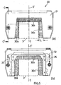
- the leakage limiter (20) of an electrolysis cell (1) for the production of aluminum provided with containment means (14, 15) having passage openings (17) for the insertion of anode rods (3) is characterized in that it comprises at least one support (21), able to surround all or part of an anode rod, and at least one flexible sealing body (30, 30a, 30b, 30c) disposed on all or part of the periphery (23) of the support (21) and intended to close all or part of the free space between the inner edge (18) of an opening (17) and an anode rod ( 3).
- the support (21) can take various forms, such as substantially rectilinear, curved or other shapes. In addition, the support (21) may be formed of different elements.
- the one or more supports (21) form an opening, or "indentation”, (26) capable of allowing lateral insertion.
- an anode rod (3) typically takes the form of a U or a three-sided frame.
- the sealing body or bodies (30, 30a, 30b, 30c) are disposed on the inner periphery (23) of the opening (26).
- the leakage limiter (20) surrounds at least three sides of the anode rod (3).
- the sealing body (30) can be of such shape that it also covers the fourth side of the rod.
- the leakage limiter (20) may optionally comprise a complementary closure element (20 '), movable or removable, adapted to limit leakage by the fourth side after insertion of the rod.
- This complementary closure element (20 ') may comprise a support (21') provided with a flexible sealing body (30 ').
- This complementary element may optionally be fixed to the fixed cover (15) or the movable cover (14) located near the anode rod.
- Figure 3 illustrates the case where the seal body is formed of a single member (30).
- Figure 4 illustrates the case where the sealing body is formed of three separate elements (30a, 30b, 30c) juxtaposed.
- the seal body abuts the anode rod, but is not necessarily in contact therewith. It can be separated by a few millimeters, typically 2 or 3 mm, without significantly reducing the sealing gain obtained with the device of the invention.
- the flexible sealing body may be formed of any flexible element able to effectively seal all or part of said free space. It may, for example, be formed of son, lamellae, spongy body or flexible tubes, or any combination thereof. It can be metallic or non-metallic.
- the flexible sealing body (30) is preferably adapted to withstand the atmosphere of the interior space (16) of the electrolysis cell and to maintain their mechanical properties at the temperatures reached in this environment.
- the flexible sealing body (30) is advantageously formed of a bundle of metal and / or non-metallic wires.
- the Applicant has noted that the wire bundle allows the maintenance of a certain seal around the anode rod, thanks to the density of the wires, and that this seal is maintained, thanks to the flexibility of the wires, despite variations inevitable from the position of the rod.
- the wires also make it possible to maintain a good seal despite the surface defects of the anode rod.
- the wires of the bundle (30) are sufficiently tight to produce a significant pressure drop between the outside and the inside of the pickup device. It has been found sufficient to use a linear density of 100 to 1000 threads per centimeter along the periphery.
- the thickness of the beam is typically greater than 0.5 cm.
- the diameter of the wires is typically between 0.1 and 1 mm.
- the angle ⁇ of opening of the wire bundle is typically between 0 and 45 °, and more typically between 0 and 30 °.
- the length L of the metal wires leaving the support is typically between 1 and 10 cm.
- At least one flexible sealing body (30, 30a, 30b, 30c) is fixed to a second support, or "mount”, (32) movable relative to the support (21), that is to say able to move relative to the support (21).
- the support (21) typically has an elongate opening (22) on its inner periphery (23), and the mount (32) is movably inserted in this opening.
- the mount (32) and flexible sealing body (30, 30a, 30b, 30c) then form a moving assembly, or "drawer", (31) which improves the self-positioning of the sealing means during the movements of the anode rod.
- the movement of the mount / seal body assembly (31) is typically substantially perpendicular to the anode rod (3).
- the flexible sealing body (30, 30a, 30b, 30c) and the mount (32) are preferably of non-magnetic materials, so as not to develop magnetic force in the presence of the field intense magnetic reign in the environment of the cell, which avoids a blockage of movement by this magnetic field.
- the mount (32) is preferably aluminum or aluminum alloy, and non-magnetic stainless steel son.
- the mobility of the elements (31) in the support (21) can facilitate maintenance or replacement thereof in case of wear or damage.
- the leakage limiter (20) further comprises at least one connecting element (25) between the support (21) and the or each mount (32), for controlling the displacement of the sealing body or bodies (30). , 30a, 30b, 30c) relative to the support (21).
- the connecting element is typically attached to the mount (32).
- At least one connecting element is advantageously an elastic element, such as a spring or an elastic blade, in order to promote the self-positioning of the brush or brushes with respect to the anode rod (3). It may be possible to use rods and / or guide means, possibly combined with one or more elastic elements.
- FIGS. 5 to 8 illustrate a preferred embodiment of the invention, in which the sealing body (30, 30a, 30b, 30c) is formed of wires fixed to a single movable frame (32) able to move by report to the framework (21).
- FIG. 5 (b) corresponds to a longitudinal sectional view of the limiter of FIG. 5 (a) which reveals the mount / wire assembly (31), called a "brush", located partly inside the support (21). ).
- the profile of the anode rod (3) is seen in dotted lines.
- the Figure 6 shows the brush (31) alone, seen in its main plane (a) and view on the edge (b).
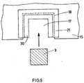
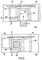
- FIGS. 9 and 10 illustrate two modes of insertion of an anode rod .
- Figure 9 corresponds to the case of a unidirectional insertion.
- Figure 10 corresponds to the case of bidirectional insertion with displacement of the leak limiter relative to the electrolysis cell.
- the support (21) and the mount (32) are typically made of metal to ensure sufficient mechanical strength. Aluminum and aluminum alloys, which are non-magnetic, can advantageously be used.
- the rigidity of the support (21) further allows the leak limiter to support, without deteriorating, the possible support of the foot of an operator.
- the leakage limiter (20) can be fixed rigidly or movably to the electrolysis cell, and more specifically to a structural element thereof or to the sensing device.
- the support (21) advantageously comprises means (24) for securing it, preferably removably, to the electrolysis cell.
- a removable attachment such as can be obtained for example by means of bolts and nuts (29), allows easy removal of the leak limiter without removing the anode.
- a movable attachment gives an additional degree of freedom to the leak limiter which allows an easier adaptation of its position relative to the anode rod.
- This additional degree of freedom is particularly useful when the passage opening (17) of the anode rod is of large size relative to the section of the rod and allows a large deflection thereof during its establishment. and / or its use.
- the leakage limiter typically has an open position ( Figure 10 (a)) and a closed position ( Figure 10 (b)).
- the leakage limiter (20) then advantageously comprises one or more complementary closure elements (33, 34), such as a plate, intended to maintain the tightness of the limiter during its movements.
- complementary elements can be fixed or mobile.
- the leakage limiter (20) movable may optionally cooperate with one or more fixed shutter element (20 ') to maintain the tightness of the device during its movements.
- the movements of the leak limiter may be guided by a guide member (35), such as a rail.
- the leakage limiter (20) contains metallic elements, especially in the vicinity of the anode rod, such as a metal support or wires, it is preferable to electrically isolate the leakage limiter of the cell from the cell. electrolysis to avoid short circuits when handling the anode. This insulation can be obtained by interposing an electrical insulator (27, 28, 28 ') between the leakage limiter and the electrolysis cell.
- an electrical insulator 27, 28, 28 '
- the leakage limiter (20) is isolated from the cell (1) by means of an insulating plate (27) interposed between the support (21) and the control means. containment (15) and using a tube (28) and a washer (28 ') interposed between the fastening means (29) and the confinement means (15).
- the simplicity of the sealing mechanism of the leak limiter according to the invention gives it a satisfactory resistance to ambient conditions, and in particular the presence of alumina dust or ground bath which could block or stop mechanisms comprising axes. pivoting or rotating.
- the leak limiter according to the invention also has the advantage of easily having a small volume.
- the total thickness of the limiter according to the invention is typically only 3 to 4 cm, which allows to easily position it between the anode frame (5) and the cover (15).
- the invention also has the advantage of not requiring manual intervention or specific actuator, which simplifies its use and increases its reliability.
Landscapes
- Chemical & Material Sciences (AREA)
- Engineering & Computer Science (AREA)
- Chemical Kinetics & Catalysis (AREA)
- Electrochemistry (AREA)
- Materials Engineering (AREA)
- Metallurgy (AREA)
- Organic Chemistry (AREA)
- Electrolytic Production Of Metals (AREA)
- Electrolytic Production Of Non-Metals, Compounds, Apparatuses Therefor (AREA)
- Inert Electrodes (AREA)
Claims (14)
- Dichtungssystem (20) für eine Elektrolysezelle (1) zur Erzeugung von Aluminium, welche mit Umschließungsmitteln (14, 15) beinhaltend Durchgangsöffnungen (17) zur Einführung von Anodenstäben (3) versehen ist, dadurch gekennzeichnet, dass es mindestens einen Träger (21), der einen Anodenstab ganz oder teilweise zu umgeben vermag, und mindestens einen flexiblen Dichtkörper (30, 30a, 30b, 30c) umfasst, der auf dem ganzen oder einem Teil des Außenumfangs (23) des Trägers (21) angeordnet und dazu bestimmt ist, den ganzen oder einen Teil des Freiraums zwischen der Innenkante (18) einer Öffnung (17) und einem Anodenstab (3) abzudichten, und dass der oder die Träger (21) eine Öffnung oder einen "Ausschnitt" (26) bilden, der geeignet ist, die seitliche Einführung eines Anodenstabs (3) zu ermöglichen.
- Dichtungssystem (20) nach Anspruch 1, dadurch gekennzeichnet, dass der oder jeder flexible Dichtkörper (30, 30a, 30b, 30c) aus mindestens einem Element gebildet ist, das unter Drähten, Lamellen, Schwammkörpern, Schläuchen oder einer Kombination daraus ausgewählt wird.
- Dichtungssystem (20) nach Anspruch 1, dadurch gekennzeichnet, dass der oder jeder flexible Dichtkörper (30, 30a, 30b, 30c) aus einem Bündel metallischer und/oder nicht metallischer Drähte gebildet ist.
- Dichtungssystem (20) nach Anspruch 3, dadurch gekennzeichnet, dass das Drahtbündel aus rostfreiem Stahl ist.
- Dichtungssystem (20) nach irgendeinem der Ansprüche 1 bis 4, dadurch gekennzeichnet, dass mindestens ein flexibler Dichtkörper (30, 30a, 30b, 30c) an einem zweiten Träger oder "Gestell" (32) befestigt ist, das in Bezug auf den Träger (21) beweglich ist.
- Dichtungssystem (20) nach Anspruch 5, dadurch gekennzeichnet, dass der flexible Dichtkörper (30, 30a, 30b, 30c) und das Gestell (32) aus unmagnetischen Werkstoffen gefertigt sind.
- Dichtungssystem (20) nach irgendeinem der Ansprüche 5 oder 6, dadurch gekennzeichnet, dass es zusätzlich mindestens ein Verbindungselement (25) zwischen dem Träger (21) und dem oder jedem Gestell (32) umfasst, um die Verschiebung des oder der Dichtkörper (30, 30a, 30b, 30c) in Bezug auf den Träger (21) zu kontrollieren.
- Dichtungssystem (20) nach Anspruch 7, dadurch gekennzeichnet, dass mindestens ein Verbindungselement (25) elastisch ist.
- Elektrolysezelle (1), dadurch gekennzeichnet, dass sie mindestens ein Dichtungssystem (20) nach irgendeinem der Ansprüche 1 bis 8 umfasst.
- Elektrolysezelle (1) nach Anspruch 9, dadurch gekennzeichnet, dass das oder jedes Dichtungssystem (20) an der Zelle starr befestigt ist.
- Elektrolysezelle (1) nach Anspruch 9, dadurch gekennzeichnet, dass das oder jedes Dichtungssystem (20) an der Zelle beweglich befestigt ist.
- Elektrolysezelle (1) nach Anspruch 11, dadurch gekennzeichnet, dass das oder jedes Dichtungssystem (20) mindestens ein zusätzliches Abdichtungselement (33, 34) umfasst, das dazu bestimmt ist, die Dichtigkeit jedes Dichtungssystems (20) bei seinen Verschiebungen aufrechtzuerhalten.
- Elektrolysezelle (1) nach irgendeinem der Ansprüche 9 bis 12, dadurch gekennzeichnet, dass das oder jedes Dichtungssystem (20) an der Zelle abnehmbar befestigt ist.
- Elektrolysezelle (1) nach irgendeinem der Ansprüche 9 bis 13, dadurch gekennzeichnet, dass mindestens eine elektrische Isolierung (27, 28, 28') zwischen der Zelle (1) und mindestens einem Dichtungssystem (20) montiert ist.
Applications Claiming Priority (1)
| Application Number | Priority Date | Filing Date | Title |
|---|---|---|---|
| PCT/FR2002/003513 WO2004035872A1 (fr) | 2002-10-14 | 2002-10-14 | Limiteur de fuite d'une cellule d'electrolyse |
Publications (3)
| Publication Number | Publication Date |
|---|---|
| EP1552040A1 EP1552040A1 (de) | 2005-07-13 |
| EP1552040B1 true EP1552040B1 (de) | 2006-02-08 |
| EP1552040B9 EP1552040B9 (de) | 2006-07-19 |
Family
ID=32104289
Family Applications (1)
| Application Number | Title | Priority Date | Filing Date |
|---|---|---|---|
| EP02795315A Expired - Lifetime EP1552040B9 (de) | 2002-10-14 | 2002-10-14 | Dichtungsystem für elektrolysezelle |
Country Status (18)
| Country | Link |
|---|---|
| US (1) | US7678244B2 (de) |
| EP (1) | EP1552040B9 (de) |
| CN (1) | CN100540751C (de) |
| AR (1) | AR041385A1 (de) |
| AT (1) | ATE317461T1 (de) |
| AU (1) | AU2002360120B2 (de) |
| BR (1) | BR0215868B1 (de) |
| CA (1) | CA2502080C (de) |
| DE (1) | DE60209150T2 (de) |
| EG (1) | EG24809A (de) |
| ES (1) | ES2258170T3 (de) |
| IS (1) | IS2283B (de) |
| NO (1) | NO339151B1 (de) |
| NZ (1) | NZ538750A (de) |
| RS (1) | RS20050283A (de) |
| SI (1) | SI1552040T1 (de) |
| UA (1) | UA78390C2 (de) |
| WO (1) | WO2004035872A1 (de) |
Families Citing this family (19)
| Publication number | Priority date | Publication date | Assignee | Title |
|---|---|---|---|---|
| WO2004035872A1 (fr) | 2002-10-14 | 2004-04-29 | Aluminium Pechiney | Limiteur de fuite d'une cellule d'electrolyse |
| FR2854906B1 (fr) | 2003-05-12 | 2006-06-16 | Ecl | Organe de manutention de connecteurs de cellules d'electrolyse destinees a la production d'aluminium |
| WO2005009685A1 (en) * | 2003-07-23 | 2005-02-03 | Pintab Services Pty Ltd | Smelting device |
| RU2269610C1 (ru) * | 2004-07-23 | 2006-02-10 | Общество с ограниченной ответственностью "Инженерно-технологический центр" | Устройство для сжигания анодных газов алюминиевого электролизера |
| RU2303661C2 (ru) * | 2005-10-07 | 2007-07-27 | Общество с ограниченной ответственностью "Русская инжиниринговая компания" | Уплотнитель анодной штанги электролизера для производства алюминия |
| US8252156B2 (en) * | 2006-10-18 | 2012-08-28 | Alcoa Inc. | Electrode containers and associated methods |
| AU2007350649A1 (en) * | 2007-04-03 | 2008-10-09 | Pedonese Services Pty Ltd | Sealing apparatus for an aluminium smelter |
| CN101709485B (zh) * | 2009-12-18 | 2012-07-04 | 中国铝业股份有限公司 | 一种采用惰性阳极生产原铝的铝电解槽 |
| FR3012473A1 (fr) * | 2013-10-30 | 2015-05-01 | Rio Tinto Alcan Int Ltd | Dispositif d'etancheite pour capot de cellule d'electrolyse |
| FR3016894B1 (fr) | 2014-01-27 | 2017-09-01 | Rio Tinto Alcan Int Ltd | Cuve d'electrolyse comportant un ensemble anodique contenu dans une enceinte de confinement |
| FR3016901B1 (fr) * | 2014-01-27 | 2016-01-15 | Rio Tinto Alcan Int Ltd | Cuve d'electrolyse pour la production d'aluminium comprenant un dispositif de collecte de gaz. |
| FR3016896B1 (fr) * | 2014-01-27 | 2016-01-15 | Rio Tinto Alcan Int Ltd | Caisson de cuve d'electrolyse. |
| GB2525156B (en) * | 2014-02-14 | 2016-10-12 | Dubai Aluminium Pjsc | Start-up fuse for aluminium reduction electrolysis cell |
| CN105350021B (zh) * | 2015-11-19 | 2017-12-22 | 江苏大学 | 一种用于提高铝电解槽气密性的槽顶结构 |
| NO349526B1 (en) * | 2016-07-13 | 2026-02-09 | Norsk Hydro As | Electrolysis cell and a method for repairing same |
| RU2667144C2 (ru) * | 2016-08-15 | 2018-09-17 | Гуйян Алюминум Магнизиум Дизайн Энд Рисерч Инститьют Ко., Лтд | Новые способ и устройство для укрывания анода в алюминиевом электролизере |
| CN107099821B (zh) * | 2017-06-23 | 2023-07-25 | 重庆科技学院 | 一种预焙阳极铝电解槽上部全密封装置 |
| FR3109781A1 (fr) * | 2020-04-29 | 2021-11-05 | Rio Tinto Alcan International Limited | Capot avec joint résilient pour cuve d’électrolyse |
| CN116555842B (zh) * | 2023-02-27 | 2025-08-05 | 中国科学院广州能源研究所 | 一种框架可拆式电解槽烟气收集罩结构 |
Family Cites Families (20)
| Publication number | Priority date | Publication date | Assignee | Title |
|---|---|---|---|---|
| US3093369A (en) * | 1959-06-24 | 1963-06-11 | Pechiney Prod Chimiques Sa | Clamping device for electric connections |
| FR1437465A (fr) | 1965-02-17 | 1966-05-06 | Pechiney Prod Chimiques Sa | Procédé pour la suspension du système anodique des cuves d'électrolyse à anode continue et appareillage pour la mise en oeuvre de ce procédé |
| FR2039543A5 (de) * | 1969-04-14 | 1971-01-15 | Duclaux Daniel | |
| US3888757A (en) * | 1973-06-07 | 1975-06-10 | Nl Kraanbouw Mij B V | Anode rod clamping assembly |
| IN142921B (de) * | 1973-08-09 | 1977-09-10 | Uhde Gmbh Friedrich | |
| EP0045148B1 (de) * | 1980-07-30 | 1985-05-08 | Imperial Chemical Industries Plc | Elektrode zur Verwendung in einer Elektrolysezelle |
| CH647007A5 (de) * | 1981-05-20 | 1984-12-28 | Alusuisse | Anode fuer eine schmelzflusselektrolysezelle. |
| CA1263948A (en) | 1984-10-18 | 1989-12-19 | Wayne R. Hale | Anode clamp |
| NO172250C (no) * | 1990-05-07 | 1993-06-23 | Elkem Aluminium | Anordning for lukking av anodetoppen paa en soederberganodei en elektrolysecelle for fremstilling av aluminium |
| FR2694945B1 (fr) * | 1992-08-20 | 1994-10-07 | Pechiney Aluminium | Superstructure de cuve d'électrolyse de très haute intensité pour la production d'aluminium. |
| WO1994012696A1 (en) | 1992-11-20 | 1994-06-09 | Bechtel Group, Inc. | Electrode cap with integral tank cover for acid mist collection |
| NO179415C (no) | 1994-02-21 | 1996-10-02 | Elkem Aluminium | Fremgangsmåte og anordning for lukking og kjöling av toppen av anodemantelen på en Söderberganode i en elektrolysecelle for fremstilling av aluminium |
| US5876585A (en) * | 1996-05-29 | 1999-03-02 | Schenk; Rodney J. | Anode clamp |
| CN1082101C (zh) * | 1999-04-09 | 2002-04-03 | 党建平 | 铝电解槽阳极下料排气缝制作工艺 |
| AUPQ218899A0 (en) | 1999-08-13 | 1999-09-02 | Jakovac, Vjekoslav | Anode assembly comprising separation of electrical and mechanical functions of the assembly |
| RU2186883C2 (ru) | 2000-07-28 | 2002-08-10 | Открытое акционерное общество "Красноярский алюминиевый завод" | Газосборный узел анодного устройства алюминиевого электролизера |
| DE10117116A1 (de) | 2001-04-06 | 2002-10-17 | Willi Lyrmann | Zentrisch spannender Schraubstock |
| WO2004035872A1 (fr) | 2002-10-14 | 2004-04-29 | Aluminium Pechiney | Limiteur de fuite d'une cellule d'electrolyse |
| FR2854906B1 (fr) | 2003-05-12 | 2006-06-16 | Ecl | Organe de manutention de connecteurs de cellules d'electrolyse destinees a la production d'aluminium |
| WO2005009685A1 (en) | 2003-07-23 | 2005-02-03 | Pintab Services Pty Ltd | Smelting device |
-
2002
- 2002-10-14 WO PCT/FR2002/003513 patent/WO2004035872A1/fr not_active Ceased
- 2002-10-14 ES ES02795315T patent/ES2258170T3/es not_active Expired - Lifetime
- 2002-10-14 AT AT02795315T patent/ATE317461T1/de not_active IP Right Cessation
- 2002-10-14 EP EP02795315A patent/EP1552040B9/de not_active Expired - Lifetime
- 2002-10-14 UA UAA200504491A patent/UA78390C2/uk unknown
- 2002-10-14 AU AU2002360120A patent/AU2002360120B2/en not_active Ceased
- 2002-10-14 CN CNB028297520A patent/CN100540751C/zh not_active Expired - Lifetime
- 2002-10-14 NZ NZ538750A patent/NZ538750A/en not_active IP Right Cessation
- 2002-10-14 SI SI200230312T patent/SI1552040T1/sl unknown
- 2002-10-14 DE DE60209150T patent/DE60209150T2/de not_active Expired - Lifetime
- 2002-10-14 CA CA2502080A patent/CA2502080C/fr not_active Expired - Lifetime
- 2002-10-14 BR BRPI0215868-0A patent/BR0215868B1/pt not_active IP Right Cessation
- 2002-10-14 RS YUP-2005/0283A patent/RS20050283A/sr unknown
-
2003
- 2003-09-24 AR ARP030103483A patent/AR041385A1/es active IP Right Grant
- 2003-10-14 EG EG2003100978A patent/EG24809A/xx active
-
2005
- 2005-02-09 US US11/052,755 patent/US7678244B2/en not_active Expired - Fee Related
- 2005-04-27 IS IS7826A patent/IS2283B/is unknown
- 2005-05-12 NO NO20052340A patent/NO339151B1/no not_active IP Right Cessation
Also Published As
| Publication number | Publication date |
|---|---|
| CN1685085A (zh) | 2005-10-19 |
| EP1552040B9 (de) | 2006-07-19 |
| NO339151B1 (no) | 2016-11-14 |
| CN100540751C (zh) | 2009-09-16 |
| DE60209150D1 (de) | 2006-04-20 |
| AU2002360120A1 (en) | 2004-05-04 |
| IS7826A (is) | 2005-04-27 |
| US7678244B2 (en) | 2010-03-16 |
| RS20050283A (sr) | 2007-06-04 |
| ES2258170T3 (es) | 2006-08-16 |
| DE60209150T2 (de) | 2006-11-02 |
| CA2502080C (fr) | 2011-03-29 |
| SI1552040T1 (sl) | 2006-08-31 |
| AR041385A1 (es) | 2005-05-18 |
| IS2283B (is) | 2007-09-15 |
| US20050194249A1 (en) | 2005-09-08 |
| BR0215868A (pt) | 2005-07-05 |
| EG24809A (en) | 2010-09-20 |
| NO20052340L (no) | 2005-05-12 |
| UA78390C2 (en) | 2007-03-15 |
| AU2002360120B2 (en) | 2008-08-14 |
| BR0215868B1 (pt) | 2012-09-04 |
| EP1552040A1 (de) | 2005-07-13 |
| ATE317461T1 (de) | 2006-02-15 |
| WO2004035872A1 (fr) | 2004-04-29 |
| NZ538750A (en) | 2007-05-31 |
| CA2502080A1 (fr) | 2004-04-29 |
Similar Documents
| Publication | Publication Date | Title |
|---|---|---|
| EP1552040B1 (de) | Dichtungsystem für elektrolysezelle | |
| EP2614178B1 (de) | Handhabungswerkzeug zur sicheren handhabung von verbindern für elektrolysezellen zur herstellung von aluminium | |
| EP3030696B1 (de) | Elektrolytische vorrichtung und anodenanordnung zur herstellung von aluminium, elektrolytische zelle und maschine mit solch einer vorrichtung | |
| EP3099844B1 (de) | Elektrolysetank mit einer in einem rückhaltebehälter enthaltenen anodenanordnung | |
| CA2935439A1 (fr) | Cuve d'electrolyse comportant un dispositif de levage d'ensembles anodiques | |
| OA12942A (fr) | Limiteur de fuite d'une cellule d'électrolyse. | |
| CA2935478C (fr) | Systeme de capotage pour cuve d'electrolyse | |
| FR3012473A1 (fr) | Dispositif d'etancheite pour capot de cellule d'electrolyse | |
| ZA200501882B (en) | Electrolytic cell leak limiter | |
| RU2294986C2 (ru) | Ограничитель утечки для электролизера | |
| FR3032457A1 (fr) | Module de service pour l'exploitation d'une installation de production d'aluminium | |
| CA2935484C (fr) | Caisson de cuve d'electrolyse | |
| FR3032456B1 (fr) | Machine de service pour l'exploitation d'une installation de production d'aluminium | |
| EP3164530B1 (de) | Anodenanordnung | |
| WO1989001061A1 (fr) | Four a electrolyse | |
| FR3109781A1 (fr) | Capot avec joint résilient pour cuve d’électrolyse | |
| OA17791A (fr) | Dispositif d'électrolyse et ensemble anodique destinés à la production d'aluminium, cellule d'électrolyse et installation comportant un tel dispositif |
Legal Events
| Date | Code | Title | Description |
|---|---|---|---|
| PUAI | Public reference made under article 153(3) epc to a published international application that has entered the european phase |
Free format text: ORIGINAL CODE: 0009012 |
|
| 17P | Request for examination filed |
Effective date: 20050413 |
|
| AK | Designated contracting states |
Kind code of ref document: A1 Designated state(s): AT BE BG CH CY CZ DE DK EE ES FI FR GB GR IE IT LI LU MC NL PT SE SK TR |
|
| AX | Request for extension of the european patent |
Extension state: AL LT LV MK RO SI |
|
| GRAP | Despatch of communication of intention to grant a patent |
Free format text: ORIGINAL CODE: EPIDOSNIGR1 |
|
| RAX | Requested extension states of the european patent have changed |
Extension state: RO Payment date: 20050413 Extension state: SI Payment date: 20050413 |
|
| GRAS | Grant fee paid |
Free format text: ORIGINAL CODE: EPIDOSNIGR3 |
|
| GRAA | (expected) grant |
Free format text: ORIGINAL CODE: 0009210 |
|
| AK | Designated contracting states |
Kind code of ref document: B1 Designated state(s): AT BE BG CH CY CZ DE DK EE ES FI FR GB GR IE IT LI LU MC NL PT SE SK TR |
|
| AX | Request for extension of the european patent |
Extension state: RO SI |
|
| PG25 | Lapsed in a contracting state [announced via postgrant information from national office to epo] |
Ref country code: IT Free format text: LAPSE BECAUSE OF FAILURE TO SUBMIT A TRANSLATION OF THE DESCRIPTION OR TO PAY THE FEE WITHIN THE PRESCRIBED TIME-LIMIT;WARNING: LAPSES OF ITALIAN PATENTS WITH EFFECTIVE DATE BEFORE 2007 MAY HAVE OCCURRED AT ANY TIME BEFORE 2007. THE CORRECT EFFECTIVE DATE MAY BE DIFFERENT FROM THE ONE RECORDED. Effective date: 20060208 Ref country code: AT Free format text: LAPSE BECAUSE OF FAILURE TO SUBMIT A TRANSLATION OF THE DESCRIPTION OR TO PAY THE FEE WITHIN THE PRESCRIBED TIME-LIMIT Effective date: 20060208 Ref country code: IE Free format text: LAPSE BECAUSE OF FAILURE TO SUBMIT A TRANSLATION OF THE DESCRIPTION OR TO PAY THE FEE WITHIN THE PRESCRIBED TIME-LIMIT Effective date: 20060208 |
|
| REG | Reference to a national code |
Ref country code: GB Ref legal event code: FG4D Free format text: NOT ENGLISH |
|
| REG | Reference to a national code |
Ref country code: CH Ref legal event code: EP |
|
| REG | Reference to a national code |
Ref country code: IE Ref legal event code: FG4D Free format text: LANGUAGE OF EP DOCUMENT: FRENCH |
|
| GBT | Gb: translation of ep patent filed (gb section 77(6)(a)/1977) |
Effective date: 20060329 |
|
| REF | Corresponds to: |
Ref document number: 60209150 Country of ref document: DE Date of ref document: 20060420 Kind code of ref document: P |
|
| PG25 | Lapsed in a contracting state [announced via postgrant information from national office to epo] |
Ref country code: DK Free format text: LAPSE BECAUSE OF FAILURE TO SUBMIT A TRANSLATION OF THE DESCRIPTION OR TO PAY THE FEE WITHIN THE PRESCRIBED TIME-LIMIT Effective date: 20060508 Ref country code: BG Free format text: LAPSE BECAUSE OF FAILURE TO SUBMIT A TRANSLATION OF THE DESCRIPTION OR TO PAY THE FEE WITHIN THE PRESCRIBED TIME-LIMIT Effective date: 20060508 |
|
| REG | Reference to a national code |
Ref country code: SE Ref legal event code: TRGR |
|
| REG | Reference to a national code |
Ref country code: GR Ref legal event code: EP Ref document number: 20060401170 Country of ref document: GR |
|
| PG25 | Lapsed in a contracting state [announced via postgrant information from national office to epo] |
Ref country code: PT Free format text: LAPSE BECAUSE OF FAILURE TO SUBMIT A TRANSLATION OF THE DESCRIPTION OR TO PAY THE FEE WITHIN THE PRESCRIBED TIME-LIMIT Effective date: 20060710 |
|
| REG | Reference to a national code |
Ref country code: ES Ref legal event code: FG2A Ref document number: 2258170 Country of ref document: ES Kind code of ref document: T3 |
|
| REG | Reference to a national code |
Ref country code: IE Ref legal event code: FD4D |
|
| PGFP | Annual fee paid to national office [announced via postgrant information from national office to epo] |
Ref country code: FI Payment date: 20060921 Year of fee payment: 5 |
|
| PGFP | Annual fee paid to national office [announced via postgrant information from national office to epo] |
Ref country code: TR Payment date: 20060925 Year of fee payment: 5 |
|
| PGFP | Annual fee paid to national office [announced via postgrant information from national office to epo] |
Ref country code: GR Payment date: 20060928 Year of fee payment: 5 |
|
| PG25 | Lapsed in a contracting state [announced via postgrant information from national office to epo] |
Ref country code: CH Free format text: LAPSE BECAUSE OF NON-PAYMENT OF DUE FEES Effective date: 20061031 Ref country code: LI Free format text: LAPSE BECAUSE OF NON-PAYMENT OF DUE FEES Effective date: 20061031 Ref country code: MC Free format text: LAPSE BECAUSE OF NON-PAYMENT OF DUE FEES Effective date: 20061031 |
|
| PGFP | Annual fee paid to national office [announced via postgrant information from national office to epo] |
Ref country code: IT Payment date: 20061031 Year of fee payment: 5 |
|
| PLBE | No opposition filed within time limit |
Free format text: ORIGINAL CODE: 0009261 |
|
| STAA | Information on the status of an ep patent application or granted ep patent |
Free format text: STATUS: NO OPPOSITION FILED WITHIN TIME LIMIT |
|
| 26N | No opposition filed |
Effective date: 20061109 |
|
| REG | Reference to a national code |
Ref country code: CH Ref legal event code: PL |
|
| BERE | Be: lapsed |
Owner name: ALUMINIUM PECHINEY Effective date: 20061031 Owner name: E.C.L. Effective date: 20061031 |
|
| PG25 | Lapsed in a contracting state [announced via postgrant information from national office to epo] |
Ref country code: CZ Free format text: LAPSE BECAUSE OF FAILURE TO SUBMIT A TRANSLATION OF THE DESCRIPTION OR TO PAY THE FEE WITHIN THE PRESCRIBED TIME-LIMIT Effective date: 20060208 |
|
| PG25 | Lapsed in a contracting state [announced via postgrant information from national office to epo] |
Ref country code: EE Free format text: LAPSE BECAUSE OF FAILURE TO SUBMIT A TRANSLATION OF THE DESCRIPTION OR TO PAY THE FEE WITHIN THE PRESCRIBED TIME-LIMIT Effective date: 20060208 |
|
| PG25 | Lapsed in a contracting state [announced via postgrant information from national office to epo] |
Ref country code: FI Free format text: LAPSE BECAUSE OF NON-PAYMENT OF DUE FEES Effective date: 20071014 Ref country code: LU Free format text: LAPSE BECAUSE OF NON-PAYMENT OF DUE FEES Effective date: 20061014 |
|
| PG25 | Lapsed in a contracting state [announced via postgrant information from national office to epo] |
Ref country code: GR Free format text: LAPSE BECAUSE OF NON-PAYMENT OF DUE FEES Effective date: 20060509 |
|
| PG25 | Lapsed in a contracting state [announced via postgrant information from national office to epo] |
Ref country code: CY Free format text: LAPSE BECAUSE OF FAILURE TO SUBMIT A TRANSLATION OF THE DESCRIPTION OR TO PAY THE FEE WITHIN THE PRESCRIBED TIME-LIMIT Effective date: 20060208 |
|
| PG25 | Lapsed in a contracting state [announced via postgrant information from national office to epo] |
Ref country code: IT Free format text: LAPSE BECAUSE OF NON-PAYMENT OF DUE FEES Effective date: 20071014 Ref country code: BE Free format text: LAPSE BECAUSE OF FAILURE TO SUBMIT A TRANSLATION OF THE DESCRIPTION OR TO PAY THE FEE WITHIN THE PRESCRIBED TIME-LIMIT Effective date: 20061031 |
|
| PG25 | Lapsed in a contracting state [announced via postgrant information from national office to epo] |
Ref country code: TR Free format text: LAPSE BECAUSE OF FAILURE TO SUBMIT A TRANSLATION OF THE DESCRIPTION OR TO PAY THE FEE WITHIN THE PRESCRIBED TIME-LIMIT Effective date: 20060208 |
|
| PGFP | Annual fee paid to national office [announced via postgrant information from national office to epo] |
Ref country code: SK Payment date: 20130919 Year of fee payment: 12 |
|
| PGFP | Annual fee paid to national office [announced via postgrant information from national office to epo] |
Ref country code: GB Payment date: 20131028 Year of fee payment: 12 Ref country code: SE Payment date: 20131029 Year of fee payment: 12 |
|
| PGFP | Annual fee paid to national office [announced via postgrant information from national office to epo] |
Ref country code: ES Payment date: 20131028 Year of fee payment: 12 Ref country code: NL Payment date: 20131026 Year of fee payment: 12 |
|
| REG | Reference to a national code |
Ref country code: NL Ref legal event code: V1 Effective date: 20150501 |
|
| REG | Reference to a national code |
Ref country code: SE Ref legal event code: EUG |
|
| GBPC | Gb: european patent ceased through non-payment of renewal fee |
Effective date: 20141014 |
|
| REG | Reference to a national code |
Ref country code: SK Ref legal event code: MM4A Ref document number: E 536 Country of ref document: SK Effective date: 20141014 |
|
| PG25 | Lapsed in a contracting state [announced via postgrant information from national office to epo] |
Ref country code: SK Free format text: LAPSE BECAUSE OF NON-PAYMENT OF DUE FEES Effective date: 20141014 Ref country code: SE Free format text: LAPSE BECAUSE OF NON-PAYMENT OF DUE FEES Effective date: 20141015 Ref country code: GB Free format text: LAPSE BECAUSE OF NON-PAYMENT OF DUE FEES Effective date: 20141014 |
|
| REG | Reference to a national code |
Ref country code: SI Ref legal event code: KO00 Effective date: 20150610 |
|
| PG25 | Lapsed in a contracting state [announced via postgrant information from national office to epo] |
Ref country code: NL Free format text: LAPSE BECAUSE OF NON-PAYMENT OF DUE FEES Effective date: 20150501 |
|
| REG | Reference to a national code |
Ref country code: FR Ref legal event code: PLFP Year of fee payment: 14 |
|
| REG | Reference to a national code |
Ref country code: ES Ref legal event code: FD2A Effective date: 20151126 |
|
| PGFP | Annual fee paid to national office [announced via postgrant information from national office to epo] |
Ref country code: DE Payment date: 20150922 Year of fee payment: 14 |
|
| PG25 | Lapsed in a contracting state [announced via postgrant information from national office to epo] |
Ref country code: ES Free format text: LAPSE BECAUSE OF NON-PAYMENT OF DUE FEES Effective date: 20141015 |
|
| REG | Reference to a national code |
Ref country code: FR Ref legal event code: PLFP Year of fee payment: 15 |
|
| REG | Reference to a national code |
Ref country code: DE Ref legal event code: R119 Ref document number: 60209150 Country of ref document: DE |
|
| PG25 | Lapsed in a contracting state [announced via postgrant information from national office to epo] |
Ref country code: DE Free format text: LAPSE BECAUSE OF NON-PAYMENT OF DUE FEES Effective date: 20170503 |
|
| REG | Reference to a national code |
Ref country code: FR Ref legal event code: PLFP Year of fee payment: 16 |
|
| REG | Reference to a national code |
Ref country code: FR Ref legal event code: PLFP Year of fee payment: 17 |
|
| PGFP | Annual fee paid to national office [announced via postgrant information from national office to epo] |
Ref country code: FR Payment date: 20180920 Year of fee payment: 17 |
|
| PG25 | Lapsed in a contracting state [announced via postgrant information from national office to epo] |
Ref country code: FR Free format text: LAPSE BECAUSE OF NON-PAYMENT OF DUE FEES Effective date: 20191031 |