EP1552054B1 - Verfahren und trockenpartie einer papiermaschine zur herstellung von tissuepapier - Google Patents
Verfahren und trockenpartie einer papiermaschine zur herstellung von tissuepapier Download PDFInfo
- Publication number
- EP1552054B1 EP1552054B1 EP03738820A EP03738820A EP1552054B1 EP 1552054 B1 EP1552054 B1 EP 1552054B1 EP 03738820 A EP03738820 A EP 03738820A EP 03738820 A EP03738820 A EP 03738820A EP 1552054 B1 EP1552054 B1 EP 1552054B1
- Authority
- EP
- European Patent Office
- Prior art keywords
- web
- fabric
- tissue
- reel
- roll
- Prior art date
- Legal status (The legal status is an assumption and is not a legal conclusion. Google has not performed a legal analysis and makes no representation as to the accuracy of the status listed.)
- Expired - Lifetime
Links
- 238000000034 method Methods 0.000 title claims abstract description 32
- 239000004744 fabric Substances 0.000 claims abstract description 156
- 238000007605 air drying Methods 0.000 claims abstract description 32
- 238000001035 drying Methods 0.000 claims description 14
- 238000004804 winding Methods 0.000 claims description 13
- 238000007906 compression Methods 0.000 claims description 7
- 238000000926 separation method Methods 0.000 claims description 6
- 239000007787 solid Substances 0.000 claims description 2
- 238000012546 transfer Methods 0.000 description 19
- 230000032258 transport Effects 0.000 description 11
- 230000006835 compression Effects 0.000 description 4
- 238000012545 processing Methods 0.000 description 4
- 238000004519 manufacturing process Methods 0.000 description 3
- 238000000465 moulding Methods 0.000 description 3
- 230000008901 benefit Effects 0.000 description 2
- 239000000835 fiber Substances 0.000 description 2
- 238000012986 modification Methods 0.000 description 2
- 230000004048 modification Effects 0.000 description 2
- 238000007664 blowing Methods 0.000 description 1
- 239000012141 concentrate Substances 0.000 description 1
- 230000001627 detrimental effect Effects 0.000 description 1
- 230000000694 effects Effects 0.000 description 1
- -1 for example Substances 0.000 description 1
- 238000012423 maintenance Methods 0.000 description 1
- 238000005259 measurement Methods 0.000 description 1
- 239000012858 resilient material Substances 0.000 description 1
- 238000011144 upstream manufacturing Methods 0.000 description 1
Images



Classifications
-
- D—TEXTILES; PAPER
- D21—PAPER-MAKING; PRODUCTION OF CELLULOSE
- D21F—PAPER-MAKING MACHINES; METHODS OF PRODUCING PAPER THEREON
- D21F11/00—Processes for making continuous lengths of paper, or of cardboard, or of wet web for fibre board production, on paper-making machines
- D21F11/14—Making cellulose wadding, filter or blotting paper
- D21F11/145—Making cellulose wadding, filter or blotting paper including a through-drying process
-
- B—PERFORMING OPERATIONS; TRANSPORTING
- B65—CONVEYING; PACKING; STORING; HANDLING THIN OR FILAMENTARY MATERIAL
- B65H—HANDLING THIN OR FILAMENTARY MATERIAL, e.g. SHEETS, WEBS, CABLES
- B65H19/00—Changing the web roll
- B65H19/22—Changing the web roll in winding mechanisms or in connection with winding operations
- B65H19/28—Attaching the leading end of the web to the replacement web-roll core or spindle
-
- D—TEXTILES; PAPER
- D21—PAPER-MAKING; PRODUCTION OF CELLULOSE
- D21F—PAPER-MAKING MACHINES; METHODS OF PRODUCING PAPER THEREON
- D21F11/00—Processes for making continuous lengths of paper, or of cardboard, or of wet web for fibre board production, on paper-making machines
- D21F11/006—Making patterned paper
-
- D—TEXTILES; PAPER
- D21—PAPER-MAKING; PRODUCTION OF CELLULOSE
- D21F—PAPER-MAKING MACHINES; METHODS OF PRODUCING PAPER THEREON
- D21F11/00—Processes for making continuous lengths of paper, or of cardboard, or of wet web for fibre board production, on paper-making machines
- D21F11/14—Making cellulose wadding, filter or blotting paper
-
- D—TEXTILES; PAPER
- D21—PAPER-MAKING; PRODUCTION OF CELLULOSE
- D21F—PAPER-MAKING MACHINES; METHODS OF PRODUCING PAPER THEREON
- D21F5/00—Dryer section of machines for making continuous webs of paper
- D21F5/18—Drying webs by hot air
- D21F5/182—Drying webs by hot air through perforated cylinders
-
- D—TEXTILES; PAPER
- D21—PAPER-MAKING; PRODUCTION OF CELLULOSE
- D21G—CALENDERS; ACCESSORIES FOR PAPER-MAKING MACHINES
- D21G9/00—Other accessories for paper-making machines
- D21G9/0063—Devices for threading a web tail through a paper-making machine
-
- B—PERFORMING OPERATIONS; TRANSPORTING
- B65—CONVEYING; PACKING; STORING; HANDLING THIN OR FILAMENTARY MATERIAL
- B65H—HANDLING THIN OR FILAMENTARY MATERIAL, e.g. SHEETS, WEBS, CABLES
- B65H2301/00—Handling processes for sheets or webs
- B65H2301/40—Type of handling process
- B65H2301/41—Winding, unwinding
- B65H2301/414—Winding
- B65H2301/41419—Starting winding process
- B65H2301/41425—Starting winding process involving blowing means, e.g. air blast
-
- B—PERFORMING OPERATIONS; TRANSPORTING
- B65—CONVEYING; PACKING; STORING; HANDLING THIN OR FILAMENTARY MATERIAL
- B65H—HANDLING THIN OR FILAMENTARY MATERIAL, e.g. SHEETS, WEBS, CABLES
- B65H2301/00—Handling processes for sheets or webs
- B65H2301/40—Type of handling process
- B65H2301/41—Winding, unwinding
- B65H2301/414—Winding
- B65H2301/41419—Starting winding process
- B65H2301/41426—Starting winding process involving suction means, e.g. core with vacuum supply
-
- B—PERFORMING OPERATIONS; TRANSPORTING
- B65—CONVEYING; PACKING; STORING; HANDLING THIN OR FILAMENTARY MATERIAL
- B65H—HANDLING THIN OR FILAMENTARY MATERIAL, e.g. SHEETS, WEBS, CABLES
- B65H2301/00—Handling processes for sheets or webs
- B65H2301/50—Auxiliary process performed during handling process
- B65H2301/52—Auxiliary process performed during handling process for starting
- B65H2301/522—Threading web into machine
-
- B—PERFORMING OPERATIONS; TRANSPORTING
- B65—CONVEYING; PACKING; STORING; HANDLING THIN OR FILAMENTARY MATERIAL
- B65H—HANDLING THIN OR FILAMENTARY MATERIAL, e.g. SHEETS, WEBS, CABLES
- B65H2801/00—Application field
- B65H2801/84—Paper-making machines
Definitions
- the present invention relates to paper-making machinery and, more particularly, to a paper-making machine and associated method for making a tissue paper with improved tactile qualities while improving the reel-up process.
- tissue for use in personal hygiene products and the like, it is desired to produce a tissue with good tactile qualities (i.e., silky and soft to the touch) while also achieving a high machine speed and efficiency.
- the speed and efficiency are often limited by the performance of the dry end of the machine between the final dryer and the winding station or reel-up.
- Tissue is extremely delicate and difficult to handle, especially at high machine speeds.
- the tissue web is dried by a through air dryer (“TAD"), wherein a through air drying fabric (“TAD fabric”) is used to transport the web through the TAD.
- TAD through air dryer
- TAD machine Such a TAD machine is described in WO 9624718 , which discloses a method for making through air dried tissue in which the dried tissue sheet is fully supported by a fabric up to the reel. This method eliminates the open draw between the through air dryer and the reel and thereby eliminates sheet breaks normally associated with such open draws.
- TAD-produced tissue paper may be embossed, as is described in US 3432936 , which discloses a method of producing tissue paper having a basis weight of about 10-50 g/mm2.
- tissue web due to the generally delicate nature of the tissue web, excessive transfers and handling of the web in the dry end of the machine may result in damage to the web. Such detrimental results may also occur if the web is unsupported between components within the dry end. Further, if a bulky tissue web is produced in the paper-making process, the capacity of the roll on which the web is wound may be undesirably low since the web cannot be tightly wound onto the roll. A loosely wound roll is relatively more difficult to handle and may be undesirably prone to, for example, telescoping with respect to the roll.
- Such an apparatus and method should desirably be capable of addressing the issue of separating the tissue web from a TAD fabric efficiently and at high speed, but without damage. Further, such an apparatus and method should provide for minimal transfers and other handling of the tissue web while providing support for the tissue web throughout the dry end. In addition, the apparatus and method should be directed to reducing the bulk of the tissue web, again with minimal handling and while providing the desired improved tactile quality, in order to increase roll capacity and facilitate handling of the rolls.
- a dry end section for a paper-making machine for producing a high-bulk tissue Such a machine includes a through-air dryer adapted to finally dry a paper web and a through-air drying fabric configured to transport the web through the through-air dryer.
- a separating device is also included for facilitating separation of the web from the through-air drying fabric, and the machine comprises a reel configured to receive the web.
- a single permeable fabric is wrapped about the separating device and extends to the reel, wherein the single permeable fabric is configured to receive the web directly thereon from the through-air drying fabric and to transport the web directly to the reel without free draw of the web.
- Another advantageous aspect of the present invention comprises a dry end section for a paper-making machine for producing a high-bulk tissue.
- a paper-making machine for producing a high-bulk tissue.
- Such a machine includes a through-air dryer adapted to finally dry a paper web and a through-air drying fabric configured to transport the web through the through-air dryer.
- a separating device is further included for separating the web from the through-air drying fabric such that the web is received directly on the separating device.
- a roll is disposed adjacent to the separating device so as to define a nip therebetween and to form a web-compressing device.
- a single fabric is wrapped about the roll, passes through the nip, and extends to a reel configured to receive the web, wherein the single fabric is configured to receive the web thereon at the nip and to transport the web from the nip to the reel, at which point the web is transferred directly from the single fabric to a reel without free draw of the web.
- Yet other advantageous aspects of the present invention comprise methods for making a tissue with enhanced tactile quality and facilitating reel-up of the tissue in a dry end of a tissue paper-making machine, each method corresponding to the processing of a tissue web with the respective dry end section for a paper-making machine for producing a high bulk tissue as described herein, as will be appreciated by one skilled in the art.
- embodiments of the present invention provide a method and apparatus directed to a dry end of a tissue paper-making machine for making a tissue web providing improved tactile qualities while improving the handling of the tissue web in the dry end.
- Embodiments of the present invention further address the issue of separating the tissue web from a TAD fabric efficiently and at high speed, but without damage and while minimizing transfers and other handling of the tissue web, by using a suction roll for separating the web from the TAD fabric, wherein the suction roll is disposed adjacent to an additional roll to also form a web-compressing device. The web is then wound directly onto the roll or transported directly thereto by a single fabric passing through the web-compressing device.
- embodiments of the present invention reduce the number of fabrics, and components associated therewith, used in the dry end, thereby simplifying the paper-making machine, reducing the handling of the web, and reducing the cost and maintenance requirements of the machine. Therefore, the present invention provides distinct advantages as further detailed herein.
- the web 30 may be pre-dried by another type of dryer such as, for example, an impingement dryer (not shown).
- an impingement dryer not shown
- embodiments of the present invention describing a dry end 10 are not intended to be restrictive with respect to the processing of the web 30 prior to the web 30 being finally dried by the through air dryer 20.
- a transfer device 50 maybe disposed adjacent to the TAD fabric 40 about where the web 30 is received in order to facilitate the transfer of the web 30 onto the TAD fabric 40.
- the TAD fabric 40 is generally an open structured drying fabric and the web 30 will tend to become drawn into the structure of the TAD fabric 40 as the web 30 is processed through the TAD 20 and other processing devices such as, for instance, a molding device 60 which, in one embodiment, is disposed before the TAD 20 and adjacent to the TAD fabric 40.
- a molding device 60 is configured to impart suction on the web 30 through the TAD fabric 40 so as to draw the web 30 into the fabric structure and form a structured three-dimensional fiber network.
- the finally-dried web 30 has a basis weight of between about 10 g/m 2 and about 50 g/m 2 and a dry caliper of between about 0.2 mm and about 0.5 mm, and thus a density of between about 20 kg/m 3 and about 250 kg/m 3 , after leaving the TAD 20.
- a tissue web 30 is extremely delicate and difficult to handle, especially at high machine speeds. As such, following the drying process, it is typically difficult to separate the tissue web 30 from a TAD fabric 40 into which the web 30 has become drawn. Further, a tissue web 30 is at less risk of damage if handled by fewer machine components and is supported (i.e., not subjected to free draw) during the drying process.
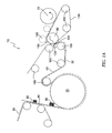
- the web 30 is separated from the TAD fabric 40, following final drying of the web 30 by the TAD 20, by a separating device 90 having a permeable fabric 130 wrapped thereabout.
- the separating device 90 may comprise, for example, a suction-configured reel drum or a suction roll (referred to herein as "suction roll 90") for separating the web 30 from the TAD fabric 40. More particularly, the TAD fabric 40 is guided about the TAD 20 by a plurality of turning rolls 100. Following final drying of the web 30 by the TAD 20, the TAD fabric 40 is directed so as to run tangentially to the suction roll 90 so as to define a web transfer point 110 between the TAD fabric 40 and the permeable fabric 130. Thus, the suction roll 90 imparts suction through the permeable fabric 130, as discussed below, so as to facilitate the transfer of the web 30 thereto.
- suction roll 90 imparts suction through the permeable fabric 130, as discussed below, so as to facilitate the transfer of the web 30 thereto.
- an air-emitting device 120 such as, for example, an air knife or an air shower, may be disposed adjacent to the TAD fabric 40 about the web transfer point 110.
- the air-emitting device 120 is directed/configured to emit air through the TAD fabric 40 and against the web 30 so as to provide assistance in separating the web 30 from the TAD fabric 40 only as the web 30 is initially being threaded through the dry end 10.
- the leading edge of the web 30 is first separated from the TAD fabric 40 by the suction roll 90 in conjunction with the air-emitting device 120, wherein the permeable fabric 130 is configured to allow the suction roll 90 to apply the suction therethrough to the tissue web 30.
- the permeable fabric 130 is configured to allow the suction roll 90 to apply the suction therethrough to the tissue web 30.
- the web 30 is received directly on the permeable fabric 130 and the air-emitting device 120 is deactivated.
- the permeable fabric 130 then solely transports the web 30 from the suction roll 90 to the reel 70. That is, in advantageous embodiments of the present invention, only one permeable fabric 130 extends from the suction roll 90 to the reel 70 and only that permeable fabric 130 contacts and supports the web 30 therebetween.
- the web 30 is further transported from the TAD fabric 40 to the reel 70 without free draw. As such, once the web 30 is dried and separated from the TAD fabric 40, the web 30 is wound onto a reel 70 with minimal handling. More particularly, as shown in FIGS. 1A and 1B , the permeable fabric 130 wraps about the separating device 90 and about one or more turning rolls 100 such that the permeable fabric 130 runs adjacent to the reel 70 and tangentially thereto. In such a configuration, the permeable fabric 130 supports the reel 70 during the winding process, forming a "soft nip" therewith, wherein the pressure in the soft nip may be selectively controlled so as to control the tension in the web 30 as it is wound onto the reel 70.
- a high bulk tissue web 30 may lessen the capacity of a roll, may be more difficult to handle, and may be prone to telescoping on the roll. Accordingly, it may be advantageous to reduce the bulk of the web 30 prior to winding the web 30 onto the roll. Compressing the web 30 in order to reduce the bulk thereof is usually accomplished through the use of a compression device defining a compression nip between adjacent rolls.
- a compression device comprises, for example, a calender used in the manufacture of card stock.
- a calender used in the manufacture of card stock.
- a calender used in the production of card stock is typically configured to impart smoothness or gloss to the card stock surface, which is not necessarily desired with a tissue paper.
- a tissue paper For a tissue paper, a good tactile quality, softness, and silkiness are some of the more desirable characteristics.
- the separating device 90 may also be configured to facilitate running of the web 30.
- the suction roll 90 may comprise a perforated outer shell or mantle with one or more air devices disposed inside the mantle and in spaced apart relation with respect thereto.
- air devices may be configured according to the needs of the particular application and, for example, may be adjustable within the mantle or rotatable about the axis of the suction roll 90 to further facilitate adjustment of the suction roll 90 for different processes.
- the air devices may further be configured to provide suction or to emit air outwardly therefrom, as necessary.
- the mantle and the air devices may be arranged such that suction or emitted air can be selectively provided along the circumference of the mantle and/or laterally across the mantle while the mantle is rotating and transporting the web 30.
- suction or emitted air can be selectively provided along the circumference of the mantle and/or laterally across the mantle while the mantle is rotating and transporting the web 30.
- one or more air devices may be placed within the mantle of the suction roll 90 to provide suction along the circumference of the mantle from the web transfer point 110 to after the nip 150 so as to maintain the web 30 on the permeable fabric 130 therebetween.
- the necessary suction through the mantle of the suction roll 90, and the permeable fabric 130 may vary depending on the position of the web 30 with respect thereto. For example, suction is required about the web transfer point 110 to separate the web 30 from the TAD fabric 40 and to transfer the web 30 to the permeable fabric 130. However, a higher suction may be initially required when the leading edge of a new web 30 is to be separated from the TAD fabric 40, wherein the air-emitting device 120 may be simultaneously activated to facilitate the initial transfer of the web 30 to the permeable fabric 130. In one embodiment, such a higher suction may be on the order of, for example, 30 kPa.
- a lesser suction may be required to maintain the web 30 on the suction roll 90 and the permeable fabric 130, from the web transfer point 110 and through the reel nip 150.
- a lesser suction may be on the order of, for example, 5-10 kPa.
- the air devices may be configured with respect to the mantle so as to provide suction or air emission across the entire width, or at one or more selected zones across the width of the mantle, the selected zones thereby providing the necessary characteristic for the corresponding segment of the mantle while, for example, reducing the required volume capacity of the air devices. Accordingly, the air devices may be appropriately and selectively controlled to provide the necessary conditions for the web 30 about the mantle of the suction roll 90.
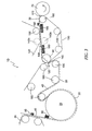
- the permeable fabric 130 then receives the web 30 directly thereon and supports and transports the web 30 through the nip 150 of the web-compressing device formed between the suction roll 90 and the adjacent roll 140.
- the suction roll 90 is further configured to provide suction along the mantle thereof from the web transfer point 110 to after the nip 150 for maintaining the web 30 on the permeable fabric 130 through the nip 150.
- one or more air devices 180 may be disposed adjacent to the permeable fabric 130 so as to facilitate runability. More particularly, the air device(s) 180 may be configured so as to retain the web 30 on the permeable fabric 130 as a new web 30 is being threaded into the dry end 10.
- FIG. 3 illustrates an alternative embodiment to the embodiment shown in FIG. 2 .
- a web-compressing arrangement may be provided instead of having a roll 140 disposed adjacent to the suction roll 90.
- the web-compressing arrangement includes a first roll 142a disposed within the loop of the permeable fabric 130 opposite to the web 30, wherein the first roll 142a is disposed between the suction roll 90 and the reel 70.
- a second roll 142b having a press fabric 145 wrapped thereabout is disposed in opposing relation to the first roll 142a so as to form a nip 148 therebetween.
- the nip 148 is further formed such that the web 30 and the permeable fabric 130 pass therethrough, whereby the web 30 is compressed between the permeable fabric 130 and the press fabric 145.
- Such a nip 148 may also be adjustable to provide the necessary pressure for compressing the web 30 to reduce the thickness thereof to the desired thickness.
- FIGS. 1A-B, 2, and 3 provide a compact dry end 10, wherein the separating device 90 serves to separate the web 30 from the TAD fabric 40 while also serving as one of the rolls in a web-compressing device.
- a dry end 10 further allows the web 30 to be transferred from the TAD fabric 40 to the reel 70 without free draw.
- Minimal components forming the dry end 10 further provides a paper-making machine with a smaller footprint and also minimizes the necessary handling of the web 30.
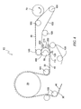
- FIGS. 4 and 5 illustrate further advantageous embodiments of the present invention.
- the suction roll 90 is configured to separate the web 30 from the TAD fabric 40 and to receive the web 30 directly thereon.
- the roll 140 is disposed adjacent to the suction roll 90 so as to form the web-compressing device, the rolls 90, 140 defining the nip 150 therebetween.
- a turning roll 100 about which the TAD fabric 40 is wrapped may be disposed adjacent to the suction roll 90 so as to form a second nip as part of a double nip web-compressing device (not shown), wherein that turning roll 100 may, in some situations, be configured as an air-emitting device so as to facilitate the transfer of the web 30 to the suction roll 90 following the second nip.
- the single fabric 130 is wrapped about the roll 140 and extends about one or more turning rolls 100 to support the reel 70 for winding the web 30 thereon.
- the suction roll 90 may be configured to provide suction about the portion of the mantle extending therebetween, as previously described.
- the roll 140 may be configured for suction as described herein and the single fabric 130 may thus be permeable or, in the alternative, the roll 140 may be a solid roll and the single fabric 130 may be smooth and impermeable.
- the suction from the suction roll 90 is intended to facilitate the transportation of the web 30 through the dry end 10
- separation of the web 30 from the TAD fabric 40 and transfer of the web 30 to the suction roll 90, as well as direction of the web 30 into the nip 150 may be further assisted by one or more blower devices 200 such as, for example, an air knife.
- one air knife 200 may be directed toward the web transfer point 110 on the downstream side thereof to facilitate transfer of the web 30 onto the suction roll 90, while another air knife 200 may be directed toward the nip 150 from the upstream side thereof in order to direct the web 30 into the nip 150.
- a suitably shaped screen 210 may be disposed between the portion of the suction roll 90 carrying the web 30 and the air knives 200.
Landscapes
- Paper (AREA)
- Winding Of Webs (AREA)
- Sanitary Thin Papers (AREA)
- Making Paper Articles (AREA)
Claims (25)
- Trockenpartie (10) für eine Papierherstellungsmaschine zum Produzieren eines voluminösen Tissues bzw. Hochbauschtissues, wobei die Maschine Folgendes aufweist:- einen Durchluftrockner (20), der dafür vorgesehen ist, eine Papierbahn (30) abschließend zu trocknen;- ein Durchluft-Trocknungsgewebe (40), welches dafür vorgesehen ist, die Bahn (30) durch den Durchlufttrockner (20) zu transportieren;- eine Trenneinrichtung (90) zum Erleichtern einer Trennung der Bahn (30) von dem Durchluft-Trocknungsgewebe (40); und- eine Rolle bzw. einen Tambour (70), welcher dafür vorgesehen ist, die Bahn (30) aufzunehmen;dadurch gekennzeichnet , dass die Maschine des Weiteren Folgendes aufweist:- ein einzelnes, durchlässiges Gewebe (130), welches um die Trenneinrichtung (90) umwickelt ist und sich bis zu der Rolle (70) erstreckt, wobei das einzelne, durchlässige Gewebe (130) dafür vorgesehen ist, die Bahn (30) direkt auf sich von dem Durchluft-Trocknungsgewebe (40) zu empfangen und die Bahn (30) direkt zu der Rolle (70) ohne einen freien Zug der Bahn (30) zu transportieren.
- Trockenpartie nach Anspruch 1, welche des Weiteren eine Walze (140) aufweist, die benachbart zu der Trenneinrichtung (90) angeordnet ist, um einen Nip (150) dazwischen festzulegen, wobei durch den Nip (150) das einzelne, durchlässige Gewebe (130) verläuft, und um eine die Bahn pressende Einrichtung zu bilden, welche dafür vorgesehen ist, die Bahn (30) vor dem Aufwickeln der Bahn (30) auf die Rolle (70) zu pressen.
- Trockenpartie nach Anspruch 1, wobei das einzelne, durchlässige Gewebe (130) dafür vorgesehen ist, die Rolle (70) zu unterstützen, um das Wickeln der Bahn (30) auf die Rolle (70) zu erleichtern.
- Trockenpartie nach Anspruch 1, welche des Weiteren eine Aufrolltrommel (160) aufweist, welche benachbart zu der Rolle (70) angeordnet ist, um einen Rollennip (170) dazwischen zu bilden, wobei das einzelne, durchlässige Gewebe (130) die Bahn (30)durch den Rollennip (170) transportiert, wobei die Aufrolltrommel (160) dafür vorgesehen ist, die Rolle (70) zu unterstützen, um das Wickeln der Bahn (30) auf die Rolle (70) zu erleichtern.
- Trockenpartie nach Anspruch 1, wobei die Trenneinrichtung eine Saugwalze (90) aufweist, wobei die Walze (90) einen perforierten Mantel und eine innerhalb des Mantels angeordnete Saugvorrichtung aufweist, die bezüglich desselben einen Abstand aufweist, wobei die Saugvorrichtung dafür vorgesehen ist, selektiv einen Saugbereich um den Mantel zu erzeugen.
- Trockenpartie nach Anspruch 5, wobei die Saugeinrichtung einstellbar innerhalb des Mantels angeordnet ist, wobei der Mantel eine Achse definiert und die Saugeinrichtung innerhalb des Mantels so angeordnet ist, dass sie um die Achse rotierbar ist.
- Trockenpartie nach Anspruch 1, wobei die Trenneinrichtung (90) dafür vorgesehen ist, eine einstellbare Absaugung zum Trennen der Bahn (30) von dem Durchluft-Trocknungsgewebe (40) zu erzeugen, wobei die Trockenpartie des Weiteren eine Luftausgabeeinrichtung (120,200) aufweist, die benachbart zu der Trenneinrichtung (90) angeordnet und dafür vorgesehen ist, die Trennung der Bahn (30) von dem Durchluft-Trocknungsgewebe (40) zu erleichtern.
- Trockenpartie nach Anspruch 1, welche des Weiteren eine die Bahn pressende Einrichtung aufweist, welche zwischen der Trenneinrichtung (90) und der Rolle (70) angeordnet ist, wobei die die Bahn pressende Einrichtung eine erste Walze (142a) aufweist, welche benachbart zu dem einzelnen, durchlässigen Gewebe (130) gegenüber der Bahn (30) angeordnet ist, wobei die die Bahn pressende Einrichtung des Weiteren eine zweite Walze (142b) aufweist, um welche ein Pressgewebe (145) umhüllend angeordnet ist, wobei die zweite Walze (142b) der ersten Walze (142a) so gegenüberliegt, dass sie einen Nip (148) derart dazwischen bildet, dass das Pressgewebe (145) sich durch den Nip (148) erstreckt, wobei das einzelne, durchlässige Gewebe (130) dafür vorgesehen ist, die Bahn (30) derart durch den Nip (148) zu transportieren, dass die Bahn (30) zwischen dem einzelnen, durchlässigen Gewebe (130) und dem Pressgewebe (145) gedrückt wird, bevor die Bahn (30) von der Rolle (70) aufgenommen wird.
- Trockenpartie (10) für eine Papierherstellungsmaschine zum Produzieren eines voluminösen Tissues bzw. Hochbauschtissues, wobei die Maschine Folgendes aufweist:- einen Durchluftrockner (20), der dafür vorgesehen ist, eine Papierbahn (30) abschließend zu trocknen;- ein Durchluft-Trocknungsgewebe (40), welches dafür vorgesehen ist, die Bahn (30) durch den Durchlufttrockner (20) zu transportieren;- eine Trenneinrichtung (90) zum Trennen der Bahn von dem Durchluft-Trocknungsgewebe (40), wobei die Trenneinrichtung (90) des Weiteren dafür vorgesehen ist, die Bahn (30) direkt auf sich aufzunehmen;- eine Walze (140), welche benachbart zu der Trenneinrichtung (90) angeordnet ist, um einen Nip (150) dazwischen festzulegen und eine die Bahn pressende Einrichtung zu bilden; und- eine Rolle bzw. einen Tambour (70), welcher dafür vorgesehen ist, die Bahn (30) aufzunehmen;dadurch gekennzeichnet , dass die Maschine des Weiteren Folgendes aufweist:- ein einzelnes Gewebe (130), welches dafür vorgesehen ist, um die Walze (140) umhüllend angeordnet zu sein, durch den Nip (150) zu verlaufen und sich bis zu der Rolle (70) zu erstrecken, wobei das einzelne Gewebe (130) dafür vorgesehen ist, die Bahn (30) auf sich an dem Nip (150) aufzunehmen und die Bahn (30) von dem Nip (150) zu der Rolle (70) zu transportieren, wobei die Bahn (30) direkt von dem einzelnen Gewebe (130) zu der Rolle (70) ohne einen freien Zug der Bahn (30) transportiert wird.
- Trockenpartie nach Anspruch 9, wobei die Trenneinrichtung eine Saugwalze (90) aufweist, wobei die Walze (90) einen perforierten Mantel und eine innerhalb des Mantels angeordnete Saugvorrichtung aufweist, die bezüglich desselben einen Abstand aufweist, wobei die Saugvorrichtung dafür vorgesehen ist, selektiv einen Saugbereich um den Mantel zu erzeugen.
- Trockenpartie nach Anspruch 10, wobei die Saugeinrichtung einstellbar innerhalb des Mantels angeordnet ist, wobei der Mantel eine Achse definiert und die Saugeinrichtung innerhalb des Mantels so angeordnet ist, dass sie um die Achse rotierbar ist.
- Trockenpartie nach Anspruch 10, wobei die Trenneinrichtung (90) dafür vorgesehen ist, eine einstellbare Absaugung zum Trennen der Bahn (30) von dem Durchluft-Trocknungsgewebe (40) zu erzeugen, wobei die Trockenpartie des Weiteren eine Luftausgabeeinrichtung (120,200) aufweist, die benachbart zu der Trenneinrichtung (90) angeordnet und dafür vorgesehen ist, die Trennung der Bahn (30) von dem Durchluft-Trocknungsgewebe (40) zu erleichtern.
- Trockenpartie nach Anspruch 10, wobei die benachbart zu der Trenneinrichtung (90) angeordnete Walze (140) eine Saugwalze und das einzelne Gewebe (130) ein durchlässiges Gewebe ist.
- Trockenpartie nach Anspruch 10, wobei die benachbart zu der Trenneinrichtung (90) angeordnete Walze (140) eine massive Walze ist und das einzelne Gewebe (130) entweder ein glattes Gewebe oder ein undurchlässiges Gewebe ist.
- Verfahren zum Herstellen eines Tissues mit verbesserter fühlbarer Qualität und zum Erleichtern des Aufrollens des Tissues in einer Trockenpartie (10) einer Tissue-Papierherstellungsmaschine, wobei das Verfahren Folgendes aufweist:- abschließendes Trocknen einer Tissuebahn (30) auf einem Durchluft-Trocknungsgewebe (40) mit einem Durchluftrockner (20);- Trennen der Tissuebahn (30) von dem Durchluft-Trocknungsgewebe (40) mittels einer Trenneinrichtung (90), um welche ein einzelnes, durchlässiges Gewebe (130) derart umhüllend angeordnet ist, dass die Tissuebahn (30) direkt auf dem einzelnen, durchlässigen Gewebe (130) aufgenommen wird;- Transportieren der Tissuebahn (30) zu einer Rolle bzw. einem Tambour (70) mit dem einzelnen, durchlässigen Gewebe (130); und- Wickeln der Tissuebahn (30) auf die Rolle (70), wobei die Tissuebahn (30) auf der Rolle (70) direkt von dem einzelnen, durchlässigen Gewebe (130) ohne einen freien Zug der Tissuebahn (30) aufgenommen wird.
- Verfahren nach Anspruch 15, wobei das Trennen der Tissuebahn (30) von dem Durchluft-Trocknungsgewebe (40) des Weiteren das Trennen der Tissuebahn (30) von dem Durchluft-Trocknungsgewebe (40) mit einer Trenneinrichtung umfasst, welche eine Saugwalze (90) aufweist, um welche das einzelne, durchlässige Gewebe (130) umhüllend angeordnet ist, wobei die Trenneinrichtung des Weiteren dafür vorgesehen ist, eine Absaugung auf die Tissuebahn (30) durch das einzelne, durchlässige Gewebe (130) aufzubringen.
- Verfahren nach Anspruch 15, welches des Weiteren das Leiten der Tissuebahn (30) und des einzelnen, durchlässigen Gewebes (130) durch eine die Bahn pressende Einrichtung aufweist, wobei die die Bahn pressende Einrichtung einen Nip (150) aufweist, der zwischen der Trenneinrichtung (90) und einer benachbart zu derselben angeordneten Walze (140) gebildet ist, und zwar vor dem Aufwickeln der Tissuebahn (30) auf die Rolle (70).
- Verfahren nach Anspruch 16, wobei das Trennen der Tissuebahn (30) von dem Durchluft-Trocknungsgewebe (40) mittels der Trenneinrichtung (90), die dafür vorgesehen ist, eine Absaugung auf die Tissuebahn (30) durch das einzelne, durchlässige Gewebe (130) aufzubringen, des Weiteren das anfängliche Aufbringen einer größeren Absaugung auf die Tissue-bahn (30) aufweist, wenn das Einführende der Tissuebahn (30) zuerst von dem Durchluft-Trocknungsgewebe (40) getrennt und dann eine geringere Absaugung auf die Tissuebahn (30) nach dem anfänglichen Aufführen der Bahn (30) aufgebracht wird.
- Verfahren zum Herstellen eines Tissues mit verbesserter fühlbarer Qualität und zum Erleichtern des Aufrollens des Tissues in einer Trockenpartie (10) einer Tissue-Papierherstellungsmaschine, wobei das Verfahren Folgendes aufweist:- abschließendes Trocknen einer Tissuebahn (30) auf einem Durchluft-Trocknungsgewebe (40) mit einem Durchluftrockner (20);- Trennen der Tissuebahn (30) von dem Durchluft-Trocknungsgewebe (40) mittels einer Trenneinrichtung (90) derart, dass die Tissuebahn (30) direkt auf der Trenneinrichtung (90) aufgenommen wird;- Leiten der Tissuebahn (30) durch eine die Bahn pressende Einrichtung, welche einen Nip (150) aufweist, der zwischen der Trenneinrichtung (90) und einer benachbart zu derselben angeordneten Walze (140) gebildet ist, wobei um die Walze (140) ein einzelnes Gewebe (130) derart umhüllend angeordnet ist, dass die Tissuebahn (30) auf dem einzelnen Gewebe (130) an dem Nip (150) aufgenommen wird;- Transportieren der Tissuebahn (30) zu einer Rolle bzw. einem Tambour (70) mit dem einzelnen Gewebe (130); und- Aufwickeln der Tissuebahn (30) auf die Rolle (70), wobei die Tissuebahn (30) auf der Rolle (70) direkt von dem einzelnen Gewebe (130) ohne einen freien Zug der Tissuebahn aufgenommen wird.
- Verfahren nach Anspruch 19, wobei das Trennen der Tissuebahn (30) von dem Durchluft-Trocknungsgewebe (40) des Weiteren das Trennen der Tissuebahn (30) von dem Durchluft-Trocknungsgewebe (40) mittels der Trenneinrichtung umfasst, welche eine Saugwalze (90) aufweist, die dafür vorgesehen ist, eine Absaugung auf die Tissuebahn (30) aufzubringen.
- Verfahren nach Anspruch 20, wobei das Trennen der Tissuebahn (30) von dem Durchluft-Trocknungsgewebe (40) mittels der Trenneinrichtung (90), die dafür vorgesehen ist, eine Absaugung auf die Tissuebahn (30) aufzubringen, des Weiteren das anfängliche Aufbringen einer größeren Absaugung auf die Tissue-bahn (30) aufweist, wenn das Einführende der Tissuebahn (30) zuerst von dem Durchluft-Trocknungsgewebe (40) getrennt und dann eine geringere Absaugung auf die Tissuebahn (30) nach dem anfänglichen Aufführen der Bahn (30) aufgebracht wird.
- Verfahren nach Anspruch 15, wobei das abschließende Trocknen der Tissuebahn (30) auf dem Durchluft-Trocknungsgewebe (40) mittels des Durchlufttrockners (20) des Weiteren das abschlie-βende Trocknen der Tissuebahn (30) aufweist, welche ein Riesgewicht von zwischen ungefähr 10 g/m2 und ungefähr 50 g/m2 aufweist, und zwar auf dem Durchluft-Trocknungsgewebe (40) mittels des Durchlufttrockners (20), wobei die Bahn eine Trockendicke von zwischen ungefähr 0,2 mm und ungefähr 0,5 mm und daher eine Dichte von zwischen ungefähr 20 kg/m3 und ungefähr 250 kg/m3 aufweist.
- Verfahren nach Anspruch 22, welches des Weiteren das Leiten der Tissuebahn (30) und des einzelnen, durchlässigen Gewebes (130) durch eine die Bahn pressende Einrichtung aufweist, wobei die die Bahn pressende Einrichtung einen Nip (150) aufweist, der zwischen der Trenneinrichtung (90) und einer benachbart zu derselben angeordneten Walze (140) gebildet ist, und dafür vorgesehen ist, die Trockendicke der Bahn (30) auf zwischen ungefähr 0,15 mm und ungefähr 0,4 mm zu verringern, um eine Nachkompressionsdichte von zwischen ungefähr 25 kg/m3 und ungefähr 333,3 kg/m3 zu erzeugen, und zwar vor dem Aufwickeln der Tissuebahn (30) auf die Rolle (70).
- Verfahren nach Anspruch 19, wobei das abschließende Trocknen der Tissuebahn (30) auf dem Durchluft-Trocknungsgewebe (40) mittels des Durchlufttrockners (20) des Weiteren das abschlie-βende Trocknen der Tissuebahn (30) aufweist, welche ein Riesgewicht von zwischen ungefähr 10 g/m2 und ungefähr 50 g/m2 aufweist, und zwar auf dem Durchluft-Trocknungsgewebe (40) mittels des Durchlufttrockners (20), wobei die Bahn eine Trockendicke von zwischen ungefähr 0,2 mm und ungefähr 0,5 mm und daher eine Dichte von zwischen ungefähr 20 kg/m3 und ungefähr 250 kg/m3 aufweist.
- Verfahren nach Anspruch 24, wobei das Leiten der Tissuebahn (30) durch die die Bahn pressende Einrichtung des Weiteren das Verringern der Trockendicke der Bahn (30) auf zwischen ungefähr 0,15 mm und ungefähr 0,4 mm aufweist, um eine Nachkompressionsdichte von zwischen ungefähr 25 kg/m3 und ungefähr 333,3 kg/m3 zu erzeugen, und zwar vor dem Aufwickeln der Tissuebahn (30) auf die Rolle (70).
Priority Applications (1)
| Application Number | Priority Date | Filing Date | Title |
|---|---|---|---|
| EP05000006A EP1538259B1 (de) | 2002-06-11 | 2003-06-10 | Verfahren und Trockenpartie einer Papiermaschine zum Herstellen von Tissue-Papier |
Applications Claiming Priority (3)
| Application Number | Priority Date | Filing Date | Title |
|---|---|---|---|
| US167336 | 2002-06-11 | ||
| US10/167,336 US6743334B2 (en) | 2002-06-11 | 2002-06-11 | Method and apparatus for making a tissue paper with improved tactile qualities while improving the reel-up process for a high bulk web |
| PCT/SE2003/000948 WO2003104551A1 (en) | 2002-06-11 | 2003-06-10 | A method and a dry-end section of paper-making machine for producing a tissue paper |
Related Child Applications (2)
| Application Number | Title | Priority Date | Filing Date |
|---|---|---|---|
| EP05000006A Division EP1538259B1 (de) | 2002-06-11 | 2003-06-10 | Verfahren und Trockenpartie einer Papiermaschine zum Herstellen von Tissue-Papier |
| EP05000006.6 Division-Into | 2005-01-03 |
Publications (2)
| Publication Number | Publication Date |
|---|---|
| EP1552054A1 EP1552054A1 (de) | 2005-07-13 |
| EP1552054B1 true EP1552054B1 (de) | 2011-10-12 |
Family
ID=29710870
Family Applications (2)
| Application Number | Title | Priority Date | Filing Date |
|---|---|---|---|
| EP03738820A Expired - Lifetime EP1552054B1 (de) | 2002-06-11 | 2003-06-10 | Verfahren und trockenpartie einer papiermaschine zur herstellung von tissuepapier |
| EP05000006A Expired - Lifetime EP1538259B1 (de) | 2002-06-11 | 2003-06-10 | Verfahren und Trockenpartie einer Papiermaschine zum Herstellen von Tissue-Papier |
Family Applications After (1)
| Application Number | Title | Priority Date | Filing Date |
|---|---|---|---|
| EP05000006A Expired - Lifetime EP1538259B1 (de) | 2002-06-11 | 2003-06-10 | Verfahren und Trockenpartie einer Papiermaschine zum Herstellen von Tissue-Papier |
Country Status (5)
| Country | Link |
|---|---|
| US (2) | US6743334B2 (de) |
| EP (2) | EP1552054B1 (de) |
| AT (2) | ATE528443T1 (de) |
| AU (1) | AU2003245201A1 (de) |
| WO (1) | WO2003104551A1 (de) |
Families Citing this family (21)
| Publication number | Priority date | Publication date | Assignee | Title |
|---|---|---|---|---|
| US6797115B2 (en) * | 2002-03-29 | 2004-09-28 | Metso Paper Karlstad Ab | Method and apparatus for making a creped tissue with improved tactile qualities while improving handling of the web |
| US6743334B2 (en) * | 2002-06-11 | 2004-06-01 | Metso Paper Karlstad Aktiebolag (Ab) | Method and apparatus for making a tissue paper with improved tactile qualities while improving the reel-up process for a high bulk web |
| FI114648B (fi) * | 2003-06-18 | 2004-11-30 | Metso Paper Inc | Menetelmä ja laitteisto paperi- tai kartonkirainan kalanteroimiseksi |
| US6953516B2 (en) * | 2004-01-16 | 2005-10-11 | Kimberly-Clark Worldwide, Inc. | Process for making throughdried tissue by profiling exhaust gas recovery |
| US7452446B2 (en) | 2005-10-18 | 2008-11-18 | Kimberly-Clark Worldwide, Inc. | Apparatus and method for dewatering a fabric |
| US7442279B2 (en) * | 2005-11-04 | 2008-10-28 | Kimberly-Clark Worldwide, Inc. | Method and apparatus for producing tissue paper |
| US7767061B2 (en) * | 2006-08-02 | 2010-08-03 | Wausau Paper Towel & Tissue, Llc | Wet/dry crepe swing paper machinery |
| ITMI20060395U1 (it) * | 2006-11-15 | 2008-05-16 | Gambini Giovanni | Macchina ribobinatrice migliorata per la ribobinatura e la formazione di un rotolo di carta |
| US8616432B1 (en) * | 2012-07-31 | 2013-12-31 | Michael Hacikyan | Welding purge dam for high air flow environment |
| US8540137B1 (en) * | 2012-07-31 | 2013-09-24 | Michael Hacikyan | Adhesiveless welding purge dam |
| SE537959C2 (sv) | 2013-03-27 | 2015-12-08 | Valmet Aktiebolag | Rullstol och förfarande för upprullning av en pappersbana itorränden av en pappersmaskin |
| SE537744C2 (sv) * | 2013-04-26 | 2015-10-13 | Valmet Aktiebolag | Rullstol för upprullning av en pappersbana till en rulle ochförfarande för upprullning av en pappersbana för att bildaen rulle |
| US9511968B2 (en) | 2013-09-09 | 2016-12-06 | Valmet Aktiebolag | Reel-up and a method for winding into a roll a paper web and for starting a new roll |
| FR3030584B1 (fr) * | 2014-12-17 | 2019-05-10 | Andritz Perfojet Sas | Installation d'extraction d'eau |
| US10654122B2 (en) | 2016-02-05 | 2020-05-19 | Michael Hacikyan | Gas diffusing water degradable welding purge dam |
| CN106006138B (zh) * | 2016-06-30 | 2018-12-11 | 泉州市知产茂业工业设计有限公司 | 一种纺织机械用便捷式卷布机 |
| US10413990B2 (en) | 2016-12-01 | 2019-09-17 | Michael Hacikyan | Welding purge dam with apertured purge plates |
| SE540822C2 (en) * | 2017-03-30 | 2018-11-20 | Valmet Oy | A method of threading a fibrous web and a reel-up for carrying out the method |
| US11066785B2 (en) * | 2019-04-11 | 2021-07-20 | Solenis Technologies, L.P. | Method for improving fabric release in structured sheet making applications |
| CN114476750A (zh) * | 2020-10-23 | 2022-05-13 | 中山润晖机械科技有限公司 | 一种双组份非织造布成套设备 |
| CN114046642B (zh) * | 2022-01-07 | 2022-03-22 | 江苏骏源新材料有限公司 | 一种绝缘纸加工用的干燥装置 |
Family Cites Families (38)
| Publication number | Priority date | Publication date | Assignee | Title |
|---|---|---|---|---|
| US3432936A (en) * | 1967-05-31 | 1969-03-18 | Scott Paper Co | Transpiration drying and embossing of wet paper webs |
| FI43536B (de) * | 1967-06-20 | 1970-12-31 | Valmet Oy | |
| FR2114934A5 (de) * | 1970-12-04 | 1972-06-30 | Polytype Ag | |
| GB1389992A (en) | 1973-04-19 | 1975-04-09 | Valmet Oy | Machine for making tissue paper |
| US5031338A (en) * | 1987-02-13 | 1991-07-16 | Beloit Corporation | Vacuum roll transfer apparatus |
| US5667636A (en) * | 1993-03-24 | 1997-09-16 | Kimberly-Clark Worldwide, Inc. | Method for making smooth uncreped throughdried sheets |
| US5399412A (en) * | 1993-05-21 | 1995-03-21 | Kimberly-Clark Corporation | Uncreped throughdried towels and wipers having high strength and absorbency |
| US5607551A (en) * | 1993-06-24 | 1997-03-04 | Kimberly-Clark Corporation | Soft tissue |
| DE4425912A1 (de) * | 1993-07-30 | 1995-02-02 | Luk Getriebe Systeme Gmbh | Hydrodynamischer Strömungswandler |
| CA2142805C (en) * | 1994-04-12 | 1999-06-01 | Greg Arthur Wendt | Method of making soft tissue products |
| US5593545A (en) * | 1995-02-06 | 1997-01-14 | Kimberly-Clark Corporation | Method for making uncreped throughdried tissue products without an open draw |
| CA2144801C (en) | 1995-02-06 | 2008-01-15 | James Sigward Rugowski | Method for making uncreped throughdried tissue products without an open draw |
| US5601871A (en) * | 1995-02-06 | 1997-02-11 | Krzysik; Duane G. | Soft treated uncreped throughdried tissue |
| SE504708C2 (sv) * | 1995-09-13 | 1997-04-07 | Valmet Karlstad Ab | Sätt och anordning för överföring av en snabbt löpande färdigtorkad fiberbana, särskilt en tissuebana, från en anordning och längs en förutbestämd bana till en efterföljande anordning |
| US5779860A (en) * | 1996-12-17 | 1998-07-14 | Kimberly-Clark Worldwide, Inc. | High-density absorbent structure |
| US6149767A (en) * | 1997-10-31 | 2000-11-21 | Kimberly-Clark Worldwide, Inc. | Method for making soft tissue |
| US6074531A (en) * | 1997-03-11 | 2000-06-13 | Valmet-Karlstad Ab | Device in a measuring station |
| US5851353A (en) * | 1997-04-14 | 1998-12-22 | Kimberly-Clark Worldwide, Inc. | Method for wet web molding and drying |
| US6131784A (en) * | 1997-12-22 | 2000-10-17 | Valmet-Karlstad Ab | Threading device |
| DE19815994A1 (de) * | 1998-04-09 | 1999-10-14 | Voith Sulzer Papiertech Patent | Übergabe einer Faserstoffbahn |
| DE19848813A1 (de) * | 1998-10-22 | 2000-04-27 | Voith Sulzer Papiertech Patent | Wickelmaschine |
| DE19848816A1 (de) * | 1998-10-22 | 2000-04-27 | Voith Sulzer Papiertech Patent | Wickelmaschine |
| US6423180B1 (en) * | 1998-12-30 | 2002-07-23 | Kimberly-Clark Worldwide, Inc. | Soft and tough paper product with high bulk |
| US6183601B1 (en) * | 1999-02-03 | 2001-02-06 | Kimberly-Clark Worldwide, Inc. | Method of calendering a sheet material web carried by a fabric |
| SE516663C2 (sv) * | 1999-06-17 | 2002-02-12 | Metso Paper Karlstad Ab | Torkparti i en maskin för tillverkning av en kontinuerlig tissuepappersbana samt metod för torkning av en kontinuerlig |
| US6790315B2 (en) * | 1999-06-17 | 2004-09-14 | Metso Paper Karlstad Ab | Drying section and method for drying a paper web |
| US6325896B1 (en) | 1999-09-23 | 2001-12-04 | Valmet-Karlstad Ab | Apparatus for transferring a fast running fibrous web from a first location to a second location |
| US6398916B1 (en) | 1999-12-16 | 2002-06-04 | Valmet Karlstad Ab | Simplified through-air drying paper making machine having a twin wire forming section |
| US6749723B2 (en) * | 2000-06-28 | 2004-06-15 | Metso Paper Karlstad Ab | Measuring arrangements in a shortened dry end of a tissue machine |
| US6716308B2 (en) * | 2000-12-14 | 2004-04-06 | Kimberly-Clark Worldwide, Inc. | Method for calendering an uncreped throughdried tissue sheet |
| US6558514B2 (en) * | 2001-01-12 | 2003-05-06 | Valmet, Inc. | Web support and transferring a paper web between papermachine components |
| US6709549B2 (en) * | 2001-03-29 | 2004-03-23 | Metso Paper Karlstad Ab | Multi-reel apparatus in a paper machine |
| US6551461B2 (en) * | 2001-07-30 | 2003-04-22 | Kimberly-Clark Worldwide, Inc. | Process for making throughdried tissue using exhaust gas recovery |
| US7001487B2 (en) * | 2001-12-19 | 2006-02-21 | Kimberly-Clark Worldwide, Inc. | Method and apparatus for transporting a sheet from a dryer to a reel |
| US6740200B2 (en) * | 2001-12-19 | 2004-05-25 | Kimberly-Clark Worldwide, Inc. | Methods and system for manufacturing and finishing web products at high speed without reeling and unwinding |
| US6755940B2 (en) * | 2001-12-20 | 2004-06-29 | Kimberly-Clark Worldwide, Inc. | Method and apparatus for caliper control of a fibrous web |
| US6797115B2 (en) * | 2002-03-29 | 2004-09-28 | Metso Paper Karlstad Ab | Method and apparatus for making a creped tissue with improved tactile qualities while improving handling of the web |
| US6743334B2 (en) * | 2002-06-11 | 2004-06-01 | Metso Paper Karlstad Aktiebolag (Ab) | Method and apparatus for making a tissue paper with improved tactile qualities while improving the reel-up process for a high bulk web |
-
2002
- 2002-06-11 US US10/167,336 patent/US6743334B2/en not_active Expired - Lifetime
-
2003
- 2003-06-10 AT AT03738820T patent/ATE528443T1/de active
- 2003-06-10 AU AU2003245201A patent/AU2003245201A1/en not_active Abandoned
- 2003-06-10 EP EP03738820A patent/EP1552054B1/de not_active Expired - Lifetime
- 2003-06-10 AT AT05000006T patent/ATE530707T1/de active
- 2003-06-10 EP EP05000006A patent/EP1538259B1/de not_active Expired - Lifetime
- 2003-06-10 WO PCT/SE2003/000948 patent/WO2003104551A1/en not_active Ceased
-
2004
- 2004-03-18 US US10/803,261 patent/US7112258B2/en not_active Expired - Lifetime
Also Published As
| Publication number | Publication date |
|---|---|
| US20040181966A1 (en) | 2004-09-23 |
| EP1538259A2 (de) | 2005-06-08 |
| EP1538259B1 (de) | 2011-10-26 |
| US20030226279A1 (en) | 2003-12-11 |
| WO2003104551A1 (en) | 2003-12-18 |
| US6743334B2 (en) | 2004-06-01 |
| US7112258B2 (en) | 2006-09-26 |
| EP1538259A3 (de) | 2005-06-15 |
| AU2003245201A1 (en) | 2003-12-22 |
| ATE530707T1 (de) | 2011-11-15 |
| ATE528443T1 (de) | 2011-10-15 |
| EP1552054A1 (de) | 2005-07-13 |
Similar Documents
| Publication | Publication Date | Title |
|---|---|---|
| US6743334B2 (en) | Method and apparatus for making a tissue paper with improved tactile qualities while improving the reel-up process for a high bulk web | |
| US6797115B2 (en) | Method and apparatus for making a creped tissue with improved tactile qualities while improving handling of the web | |
| EP0733737B1 (de) | Vorrichtung zur Trocknung einer Bahn | |
| EP1047837B1 (de) | Verfahren zur herstellung eines papierblattes mit erhöhter dehnbarkeit in einer richtung quer der machine | |
| KR940001532B1 (ko) | 단일층 드라이어 섹션장치 및 웨브의 건조방법 | |
| GB2125461A (en) | Drying section for papermaking machine | |
| US6294050B1 (en) | Drying end of a machine for the production of a material web and method of drying a material web | |
| CA2229275A1 (en) | A method of and an apparatus for transferring a fast running ready-dried fibrous web, especially a tissue web, from one device and along a predetermined run to a subsequent device | |
| JP2553429B2 (ja) | ドライヤー装置 | |
| US20200087857A1 (en) | Machine and method for the production of a fibrous web | |
| US20100229419A1 (en) | System and Process for Throughdrying Tissue Products | |
| CA2216048C (en) | Papermaking dryer section with partitioned vacuum box for threading | |
| US5933979A (en) | Restraint dryer for the drying end of a papermaking machine and a method thereof | |
| US5241761A (en) | Dryer section for a paper making machine with differing suction rolls | |
| US6658758B2 (en) | Drying section with impingement drying unit | |
| EP1341963A2 (de) | Verfahren zum kalandrieren einer ungekreppten, durchblasgetrockneten tissuebahn | |
| AU2002236601A1 (en) | Method for calendering an uncreped throughdried tissue sheet | |
| US6436239B2 (en) | Method to reduce the adhesion of a damp fibrous material web to a rotating roll | |
| US20050016703A1 (en) | Smoothing device | |
| US20030019600A1 (en) | Machine for producing a fibrous material web | |
| CA1182634A (en) | High speed paper drying | |
| EP1285122A1 (de) | Vorrichtung zur bearbeitung des schrumpfens einer papierbahn beim trockenverfahren, verfahren und nach diesem verfahren herestellte faserbahn | |
| TH21465A (th) | วิธีการสำหรับการทำผลิตภัณฑ์เยื่อกระดาษที่แห้งไม่ถูกย่นโดยปราศจากแนวเปิดดึงออก |
Legal Events
| Date | Code | Title | Description |
|---|---|---|---|
| PUAI | Public reference made under article 153(3) epc to a published international application that has entered the european phase |
Free format text: ORIGINAL CODE: 0009012 |
|
| 17P | Request for examination filed |
Effective date: 20050103 |
|
| AK | Designated contracting states |
Kind code of ref document: A1 Designated state(s): AT BE BG CH CY CZ DE DK EE ES FI FR GB GR HU IE IT LI LU MC NL PT RO SE SI SK TR |
|
| AX | Request for extension of the european patent |
Extension state: AL LT LV MK |
|
| DAX | Request for extension of the european patent (deleted) | ||
| RBV | Designated contracting states (corrected) |
Designated state(s): AT DE GB IT SE |
|
| 17Q | First examination report despatched |
Effective date: 20051028 |
|
| GRAP | Despatch of communication of intention to grant a patent |
Free format text: ORIGINAL CODE: EPIDOSNIGR1 |
|
| GRAS | Grant fee paid |
Free format text: ORIGINAL CODE: EPIDOSNIGR3 |
|
| GRAA | (expected) grant |
Free format text: ORIGINAL CODE: 0009210 |
|
| AK | Designated contracting states |
Kind code of ref document: B1 Designated state(s): AT DE GB IT SE |
|
| REG | Reference to a national code |
Ref country code: GB Ref legal event code: FG4D |
|
| REG | Reference to a national code |
Ref country code: DE Ref legal event code: R096 Ref document number: 60338744 Country of ref document: DE Effective date: 20120105 |
|
| PG25 | Lapsed in a contracting state [announced via postgrant information from national office to epo] |
Ref country code: SE Free format text: LAPSE BECAUSE OF FAILURE TO SUBMIT A TRANSLATION OF THE DESCRIPTION OR TO PAY THE FEE WITHIN THE PRESCRIBED TIME-LIMIT Effective date: 20111012 |
|
| PLBE | No opposition filed within time limit |
Free format text: ORIGINAL CODE: 0009261 |
|
| STAA | Information on the status of an ep patent application or granted ep patent |
Free format text: STATUS: NO OPPOSITION FILED WITHIN TIME LIMIT |
|
| 26N | No opposition filed |
Effective date: 20120713 |
|
| REG | Reference to a national code |
Ref country code: DE Ref legal event code: R097 Ref document number: 60338744 Country of ref document: DE Effective date: 20120713 |
|
| GBPC | Gb: european patent ceased through non-payment of renewal fee |
Effective date: 20120610 |
|
| REG | Reference to a national code |
Ref country code: DE Ref legal event code: R119 Ref document number: 60338744 Country of ref document: DE Effective date: 20130101 |
|
| PG25 | Lapsed in a contracting state [announced via postgrant information from national office to epo] |
Ref country code: GB Free format text: LAPSE BECAUSE OF NON-PAYMENT OF DUE FEES Effective date: 20120610 Ref country code: DE Free format text: LAPSE BECAUSE OF NON-PAYMENT OF DUE FEES Effective date: 20130101 |
|
| REG | Reference to a national code |
Ref country code: AT Ref legal event code: PC Ref document number: 528443 Country of ref document: AT Kind code of ref document: T Owner name: METSO PAPER SWEDEN AKTIEBOLAG, SE Effective date: 20130918 |
|
| REG | Reference to a national code |
Ref country code: AT Ref legal event code: HC Ref document number: 528443 Country of ref document: AT Kind code of ref document: T Owner name: VALMET AKTIEBOLAG, SE Effective date: 20140612 |
|
| PGFP | Annual fee paid to national office [announced via postgrant information from national office to epo] |
Ref country code: IT Payment date: 20220620 Year of fee payment: 20 |
|
| PGFP | Annual fee paid to national office [announced via postgrant information from national office to epo] |
Ref country code: AT Payment date: 20220621 Year of fee payment: 20 |
|
| REG | Reference to a national code |
Ref country code: AT Ref legal event code: MK07 Ref document number: 528443 Country of ref document: AT Kind code of ref document: T Effective date: 20230610 |